Openings in
the body.
The continuous slab behind each door is removed. Rear-quarter skins now stop at separate B-post references, leaving doorways bounded by the A-posts and outer sills. Square rear openings, cambered side skins, rear wheelhouses and raised door glazing bring the visible architecture closer to the supplied photographs.
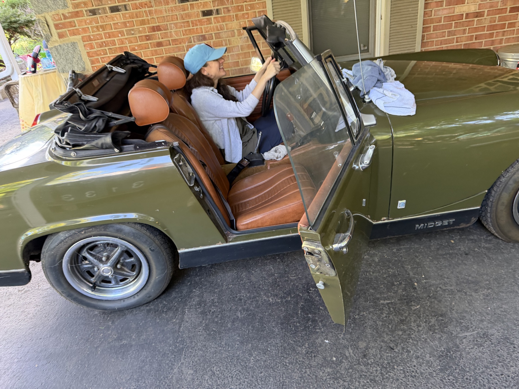
All profiles, stations, camber, post/sill sections, glazing lean and wheelhouse dimensions remain estimates. The opposite side uses an unverified symmetry assumption. The 1.2 mm skin offset is an estimated separation along vehicle X, not measured gauge or normal sheet thickness. No pixel scale or perspective rectification is claimed.
Inspect the left side
Inspect the right side
What changed and why
| Region | New reference behavior | Evidence limits |
|---|---|---|
| Door aperture | The welded rear-quarter skin stops behind the door. Separate posts and outer sill define the opening; the body shell remains fixed during general separation. | Opening dimensions, gaps, post returns, seal ledges, weld ownership and stiffness are unmeasured. No welded panel is identified as a detachable assembly. |
| Side skin | A thin, cambered surface replaces the thick beveled slab. Front wings have estimated upper returns toward the bonnet edge. | The camber and skin offset are construction estimates. Front wings now have native shell/arch-return STEP references; remaining browser skins are separate. None is tooling, a forming die or a repair template. |
| Wheel openings | Rear openings have a flat roof and rounded corners; front openings retain a rounded profile at a narrower estimated span. Separate inner wheelhouse surfaces add rear obstacles. | No fitted arch contour, tire/steering/suspension clearance, loaded ride height or tire size is recovered. Wheelhouse roof is a reference surface; detailed seams, flanges and reinforcements are absent. |
| Door surroundings | Raised main panes and front quarterlights are separate from the door skins, with matching display separation offsets. | No glass thickness, regulator, window run, seal compression or measured travel. Moving the groups together is a display convention, not a verified removal assembly. |
Close the lower front-side gap
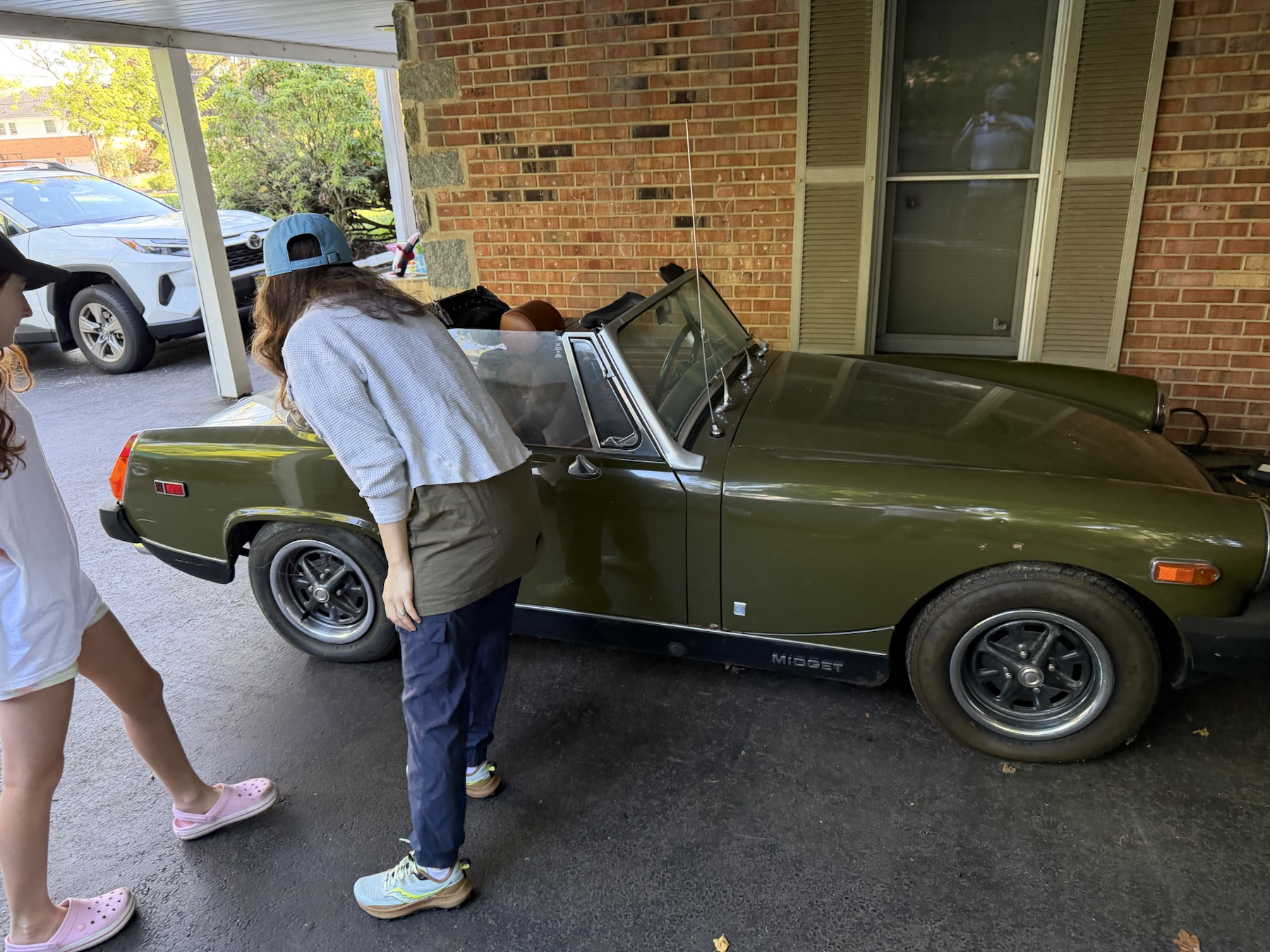
The previous front wing ended above the sill bottom, exposing the inner structure between the front wheel opening and sill. The revised skin extends down to the existing sill datum and turns inward to its lower-return edge. IMG_6329 and IMG_6341 show the continuous black lower-side treatment; they do not supply calibrated sections.
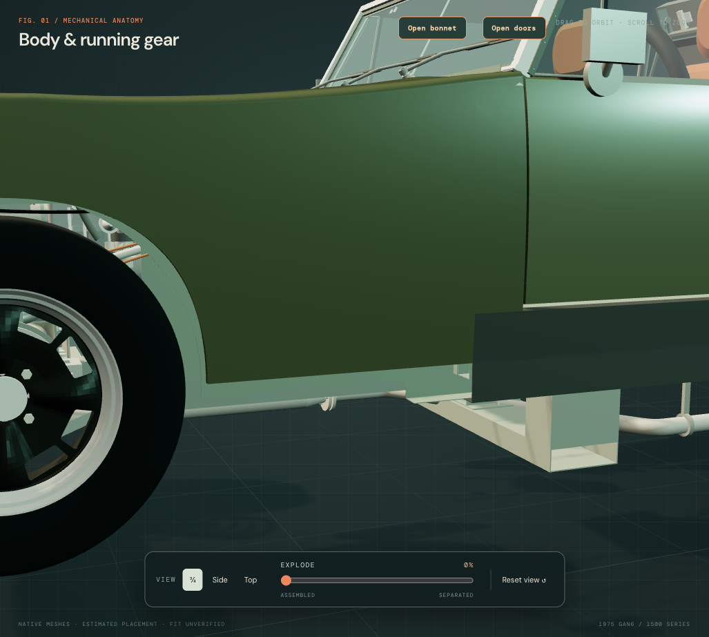
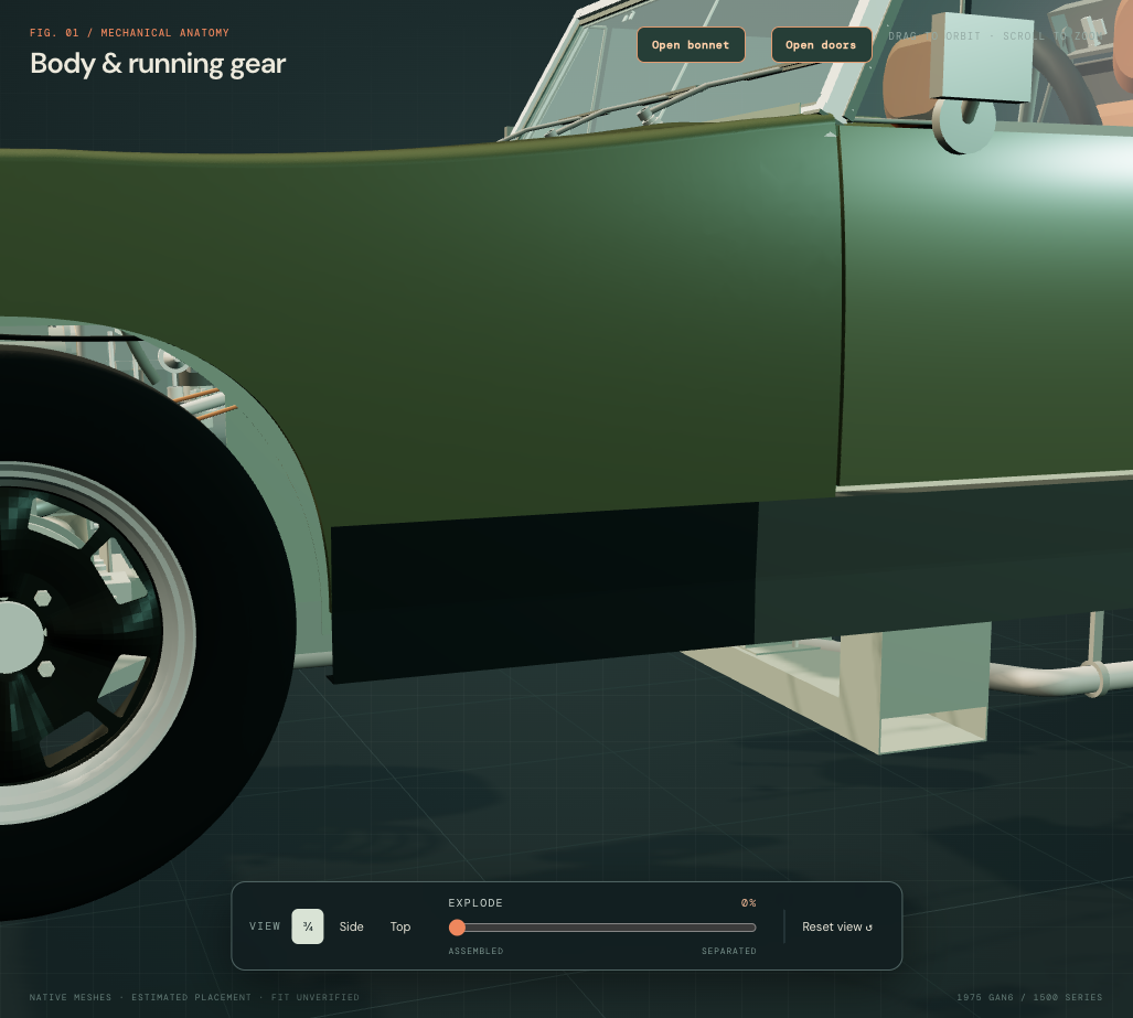
The added 76.2 mm depth, 1.5 mm projected gauge, inward fold and paint boundary are construction estimates. The black region remains part of the existing wing inspection group; its separate mesh is a color partition, not a detachable trim part or a verified factory seam. The former wing material is retained.
British Motor Heritage distinguishes rubber-bumper wings, outer sills and front sill fillers 14A4620/21. These catalog roles do not establish fitted identities, hidden laps, welds or the actual lower section. The added skin does not verify a filler arrangement, jacking strength, suspension clearance or a replacement/removal path.
Native validation confirms 75 valid positive solids, connected upper/lower wing sections, unchanged surrounding sources and no static lower-skin/tyre source overlap. The browser loads all 74 native sources with metric placement and picking intact. These checks validate the reference implementation, not actual-car fit.
Formed front-wing shells
Owner IMG_6329 shows the rounded front opening and side contour; IMG_6854/6855 show the upper shoulder and inner bonnet-edge region with the bonnet raised. The former browser side skin, straight upper ribbon and round wheel-opening tube are now replaced by native curved shells and separate inward wheel-opening returns. The existing shoulder and inner bonnet-edge boundary curves guide the new rounded section between them.
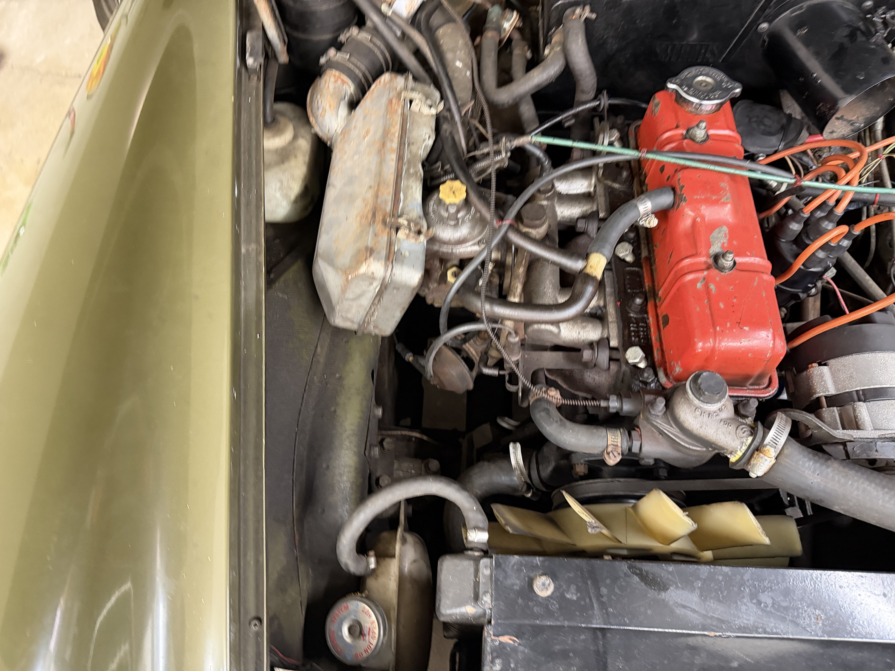
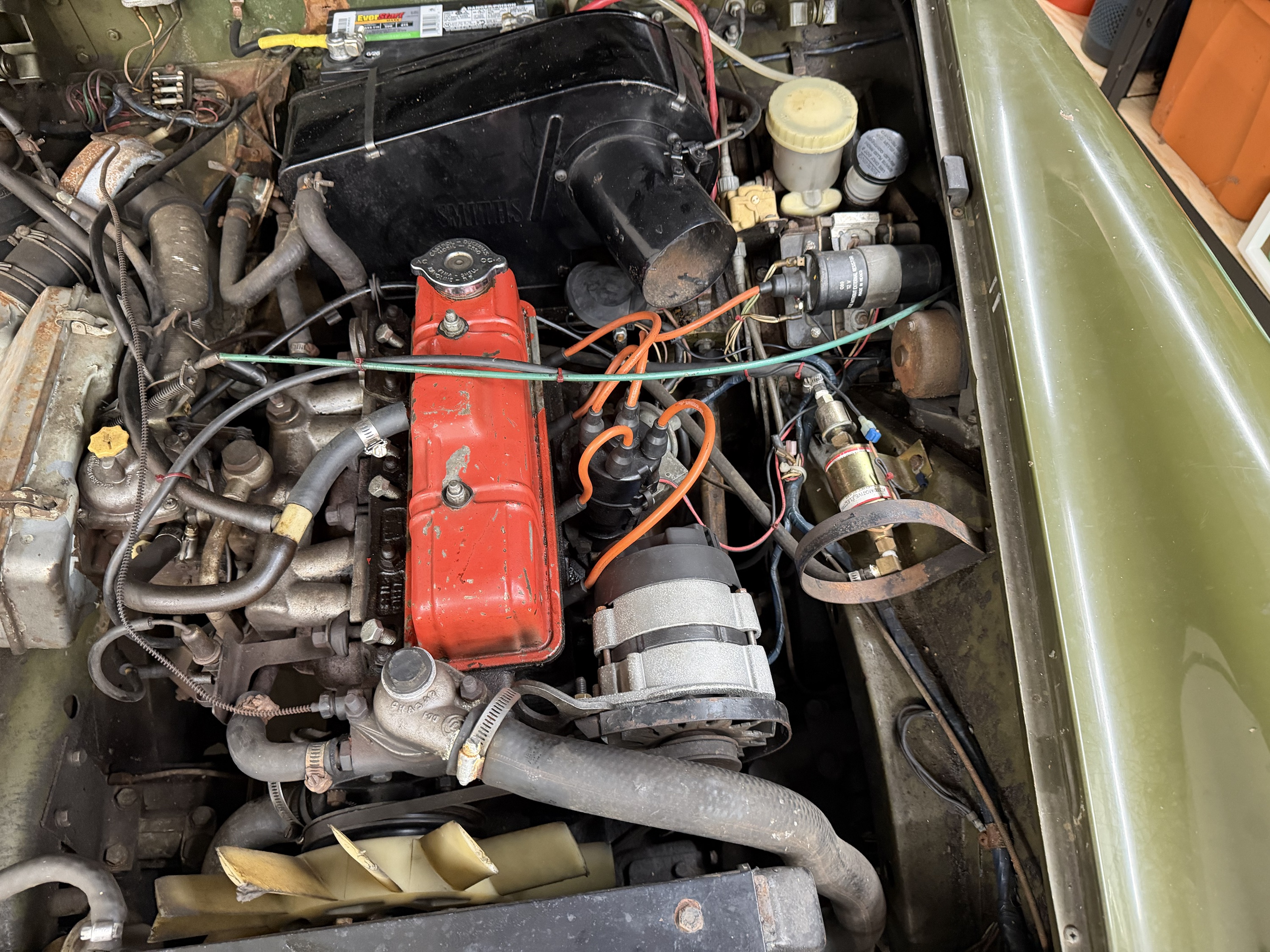
The side camber, rear/front stations, two-quadratic wheel-opening outline and side-marker envelopes retain the earlier estimated drawing. The new 1.2 mm inset follows sampled planar section normals; it is not a measured or globally normal sheet gauge. The separately modeled arch return extends about 12 mm inward with an estimated 1.3 mm section. Its touching/overlap with the skin does not establish an actual folded seam, weld or fitted return profile. No axle, track, bonnet, headlamp, engine or wheelhouse frame is shifted to create a fit.
British Motor Heritage lists CZJ594 RH and CZJ595 LH for rubber-bumper cars. These establish panel roles and configuration comparisons, not the fitted panel identity, contours or mounting map. The inner mounting flange, fasteners, rear scuttle joint and continuous headlamp transition remain incomplete. The retained neighboring sources are unregistered; zero sampled intersection, edge coincidence or visible contact would not prove actual clearance.
The wing, its return and retained side-marker envelope share an inspection translation. This is illustrative separation, not a verified detachable subassembly or removal direction. Replacement rehearsal still requires fitted fixing access, support, seams, headlamp/wiring release, adjacent-panel relationships and actual wheel/steering clearance.
Thin scuttle and A-post corners
The former rounded solid block and narrow spindle strip are replaced by a thin shroud top, three spindle apertures, downturned front/rear edges and two separate curved A-post corner references. The wiper motor, wheelboxes, spindles, casings and static arms/blades stay at their previous drawing stations. Removing the old block exposes the under-panel space those mechanisms previously occupied inside solid material.
Factory p.234 distinguishes AJA5118 and the AHA8615 North America/Sweden shroud/dash-top branch, plus a separate LH A-post/scuttle extension. The three-wheelbox plate supplies a wiper architecture comparison. BMH’s CZJ724 rubber-bumper scuttle requires North American modification; AHA7422/7423 are separate A-post/shroud extension comparisons. None identifies the fitted panel or supplies its actual hole map, section or seam.
The main top follows the former spindle-band reference plane and width. Its rear station stays at body Z0.01; the nominal block front changes from Z0.23 to the existing bonnet rear plane Z0.13, removing an estimated 84.667 mm forward drawing span. Rounded bevels of the old block are not included in that nominal span. The 1.5 mm projected-Y gauge, 12 mm edge returns and two corner profiles are construction estimates. Spindle openings use the three existing axes and estimated aperture radii. No windshield-leg receiver, body slot, shim, drain, hidden fastening or welded repair specification is invented.
The revised smaller-crown bonnet rear-center reference is about 18.9 mm above the new top (formerly 69.7 mm); the revised fascia rail’s center now shares its height plane (previously 169.3 mm above it), and the bulkhead upper edge about 12.7 mm above it. These are differences between estimated source coordinates, not measurements or clearances on the car. Lower-screen/leg intersections remain in the source contact register. A separate estimated rear dash-top now supplies two demister slots and four fixing passages through the fascia padding. Compressed seals, fitted hole maps, hidden attachment and the heater supply remain unresolved. See the outlet construction and its limits.
The shroud remains fixed in the viewer. Selectable corner pieces are architecture references; their separate selection does not establish detachable ownership. No verified welded-panel replacement, motor access, wheelbox withdrawal, wiper sweep, glass support or fitted removal path is established. The next registration priority is the cabin-height/bonnet-crown relationship, using existing photos and documentary references before accepting a closed body envelope.
A shorter connected front clip
The prior front/rear bumper envelopes spanned 3750.733 mm. Factory AKM4071/B general dimensions, p. 14, gives 11 ft 9 in, which converts to 3581.4 mm. The adjacent printed metric value is 3.36 m and conflicts with that imperial entry. The Moss GAN6 specification also lists 11 ft 9 in. The imperial conversion is the selected nominal comparison; neither entry measures this car.
The current reference allocates the entire 169.333 mm drawing excess to the front. The rear bumper/body, axle centers, wheelbase, engine/cowl and aft bonnet hinge/stay stations stay. This allocation is an estimate supported qualitatively by the existing side photo, not a factory overhang specification. No whole-car scale change or fitted body survey is implied.
The bonnet skin/formed side and front rails, wing contours, nose/upper return, lamp poses, landing panel, latch/safety openings, forward buffers/cable bends, bumper and its support beams now follow the shorter construction. Panel stations remain fixed through body Z0.835, then shorten smoothly forward. Detailed lamps and bumper hardware translate while retaining their dimensions; body beams shorten from their existing rear feet. The two wheel-opening Y/Z cuts and wheelhouse access openings stay. Forward wheelhouse ends shorten after the retained access-end region, and their upper closing faces follow the revised wing/bonnet profile. The owner-pump receiver stays at its previous drawing axis.
Body front/rear allocation, profiles, panel gauges, contours, mounting maps and all surrounding registration remain estimated. Source overlaps remain at landing/wheelhouse and lamp/bonnet comparisons, including small bowl/bonnet contacts. These are source reconstruction discrepancies, not observed interference on the car. The selected six-part roof sample has no bonnet contact; it does not establish full engine-bay, hot, moving or removal clearance. The unchanged virtual bonnet pivot and opening angle remain illustrative, with no verified catch release, hinge linkage, support state or withdrawal path.
Validation covers 60 valid native groups, 30 lamp/bumper groups retaining rigid dimensions, open wheel passages and the retained pump receiver, and displayed mesh volumes within 1% of their STEP references. The drawing moulding extremes span 3581.4 mm. These checks verify the construction and its display, not actual-car fit or a panel-repair template.
Compare the whole car with IMG_6329
The comparison below uses the existing owner side photograph, the previous model and the shorter-front model rendered from the same approximate wheel-derived camera. It preserves the published nominal axle datums and current drawing offsets. The bright trim radius is fitted independently; it is not treated as the nominal 13-inch bead seat. The camera and axle datums are unchanged between the two model renders. The front-only length allocation is described above; it is not a calibrated photo survey.
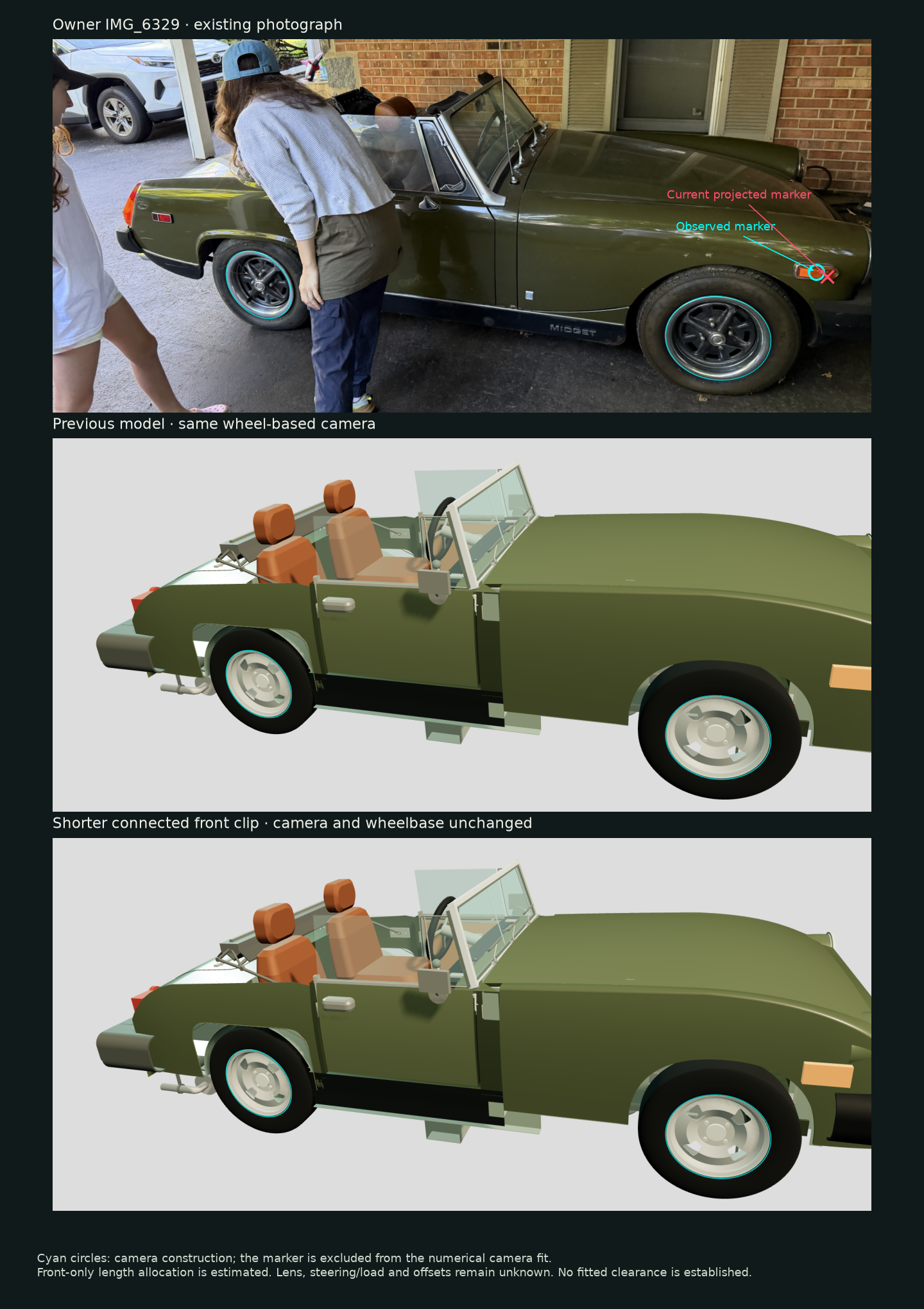
The projected marker center is now about 24 pixels farther forward and 10 pixels lower than the manually sampled owner-photo center, compared with about 88/15 pixels before the connected front-clip revision. It remained excluded from the numerical camera fit. The photo also qualitatively informed the front-only allocation, so this improvement is conditional corroboration, not an independent validation of fitted dimensions. Rear-opening and screen/corner contours also disagree visually. People obscure part of the doorway and rear opening; those hidden boundaries are not sampled.
Manual wheel-boundary samples, nominal tracks, estimated trim/cap offsets, centered principal point, square pixels, a common trim radius and straight wheel planes are assumptions. Spindle-coordinate residual RMS is about 7.5 pixels; lens distortion, steering, suspension load and fitted wheel offsets are unresolved. Screen width/rake cannot be accepted from this single view. Small wheel residuals would not independently validate the body, hidden mounts, engine/body registration or replacement clearances.
The next substantial registration priority is the engine/clutch/bellhousing and body-mount relationship, using existing owner evidence and factory references. Current body proportions and screen/corner registration also remain provisional. Keep surrounding panels and support relationships together when revising them. The comparison does not establish a replacement procedure or removal path.
Closed native rear-quarter geometry
The large welded rear-quarter skins now exist as two connected native CAD solids. The prior viewer-only surfaces are replaced after the full source loads. Their outer shoulder uses the same conditional IMG_6329 profile and camera; lower/front stations, camber and square-topped wheel openings stay. The change adds estimated inward upper returns and B-post returns for inspecting the surrounding body relationships.
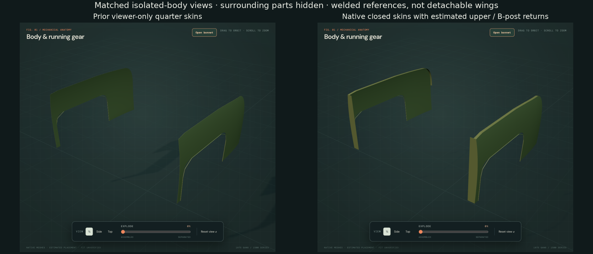
The 1.2 mm projected-X skin offset is inherited from the reference model; it is not a measured normal steel gauge. Upper-return width is an estimated 20 mm. The B-post return follows the inherited 0.68-unit inner boundary. Neither return is a surveyed pressing, flange dimension, weld seam or load-bearing joint. Right/left symmetry remains assumed. The manufacturer’s rubber-bumper wing architecture supplies component context, not fitted CZJ590/591 identity.
The native top-edge projection stays about 3.04 pixels from the held-out photo point under the unchanged conditional camera. That preserves the prior image agreement; converting the construction to CAD does not add fitted dimensional accuracy. The existing arch-edge mesh data is unchanged, and the two coarse skins remain if the source cannot load.
Selected native wheelhouse and lamp comparisons find a 1.459 mm³ overlap with each unloaded lamp body-gasket reference. This is recorded without cutting receiver holes or moving the lamp. Other checked wheelhouse/base pairs have no positive volume in this sample. These results do not prove fitted seams, gasket seating, clearance or mounting. Deck, floor, body posts, tank, lid, lamps and wheelhouse sources remain independent references.
Native rear shroud and closing walls now complement the quarters in the same reference frame. Their contact audit records estimated body joints and unresolved lid, filler and lamp relationships.
Manufacturer architecture comparisons
British Motor Heritage’s skin-panel drawing and lists distinguish rubber-bumper rear wings, A/B posts, outer sills, doors/skins and front wings. Its replacement door description excludes the North American side-impact bar; this model does not reconstruct or identify the fitted bar. The rear-body list separately identifies inner/outer wheelarch assemblies and wheelarch-to-floor reinforcements. Those lists establish component boundaries, not this car’s dimensions or fitted part identities.
Body and power-unit registration
The nominal wheelbase, tracks and wheel/rim datums remain unchanged. The maintained engine and bay sources keep their original metric meshes and previous estimated placement. IMG_6329/6341 hide the engine/body mounting datums; existing bay photos provide context without a calibrated common datum survey. This batch improves visible body architecture but does not solve the fitted engine-to-body transform, mount alignment, bonnet clearance or extraction room.
General separation moves the door skins and raised-glass groups away while the welded shell, posts, sills and wheelhouses stay fixed. Select them individually to inspect the aperture and surrounding obstacles. The display does not establish hinge adjustment, latch setting, glass removal, body bracing, welded repair order, safe support or a verified panel-removal path.
Before correction: the upper-front mismatch
This diagnostic records the geometry before the revision below. Its source hashes and camera results are retained as historical evidence.
The original IMG_6329, IMG_6855 and IMG_6856 HEIC files were reconciled with their existing website images. All three report a 24 mm equivalent focal length and a 5712 × 4284 capture. This supplies a useful camera constraint, but does not establish the principal point, crop, residual lens correction or any fitted body dimension.
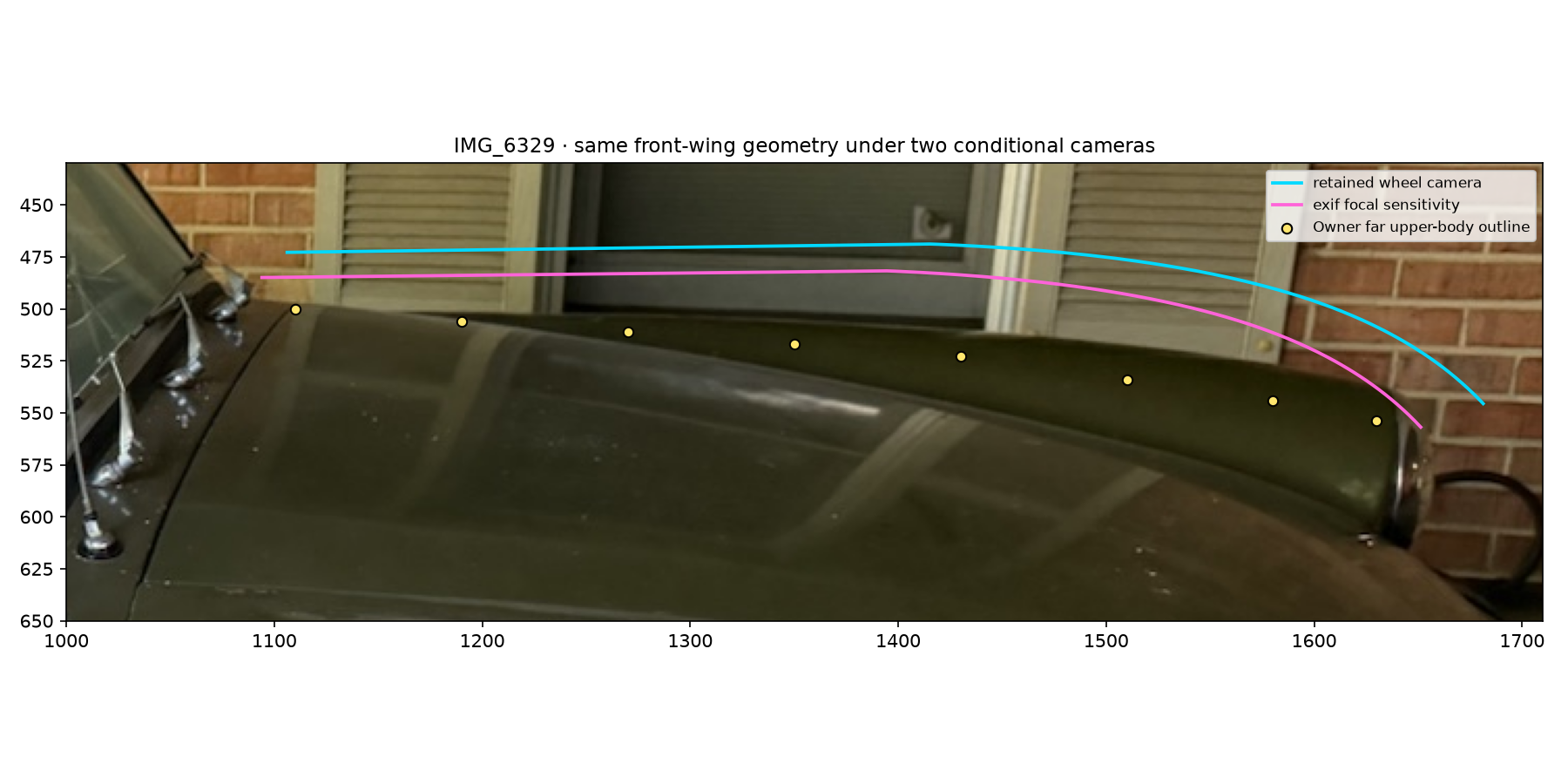
The far upper-front-body samples have vertical RMS differences of 45.97 pixels under the retained camera and 30.09 pixels under the EXIF sensitivity branch. Both projections remain above the owner samples, by about 15–58 pixels across the two branches. Wheel-center RMS remains about 7.5 pixels. These results identify the longitudinal upper profile as a substantial reconstruction priority; they do not prove the actual panel heights, lens calibration or correspondence of every visible contour.
A uniform height-only diagnostic prefers different corrections under the two camera hypotheses and still leaves residuals. Those probes are stored in the evidence file and are not applied to the model. A coherent correction must address bonnet, wings, scuttle, hinges and closing interfaces together. Moving the whole body or powertrain to improve one photograph would not establish fitted mounting.
Why the engine-bay camera does not yet locate the engine
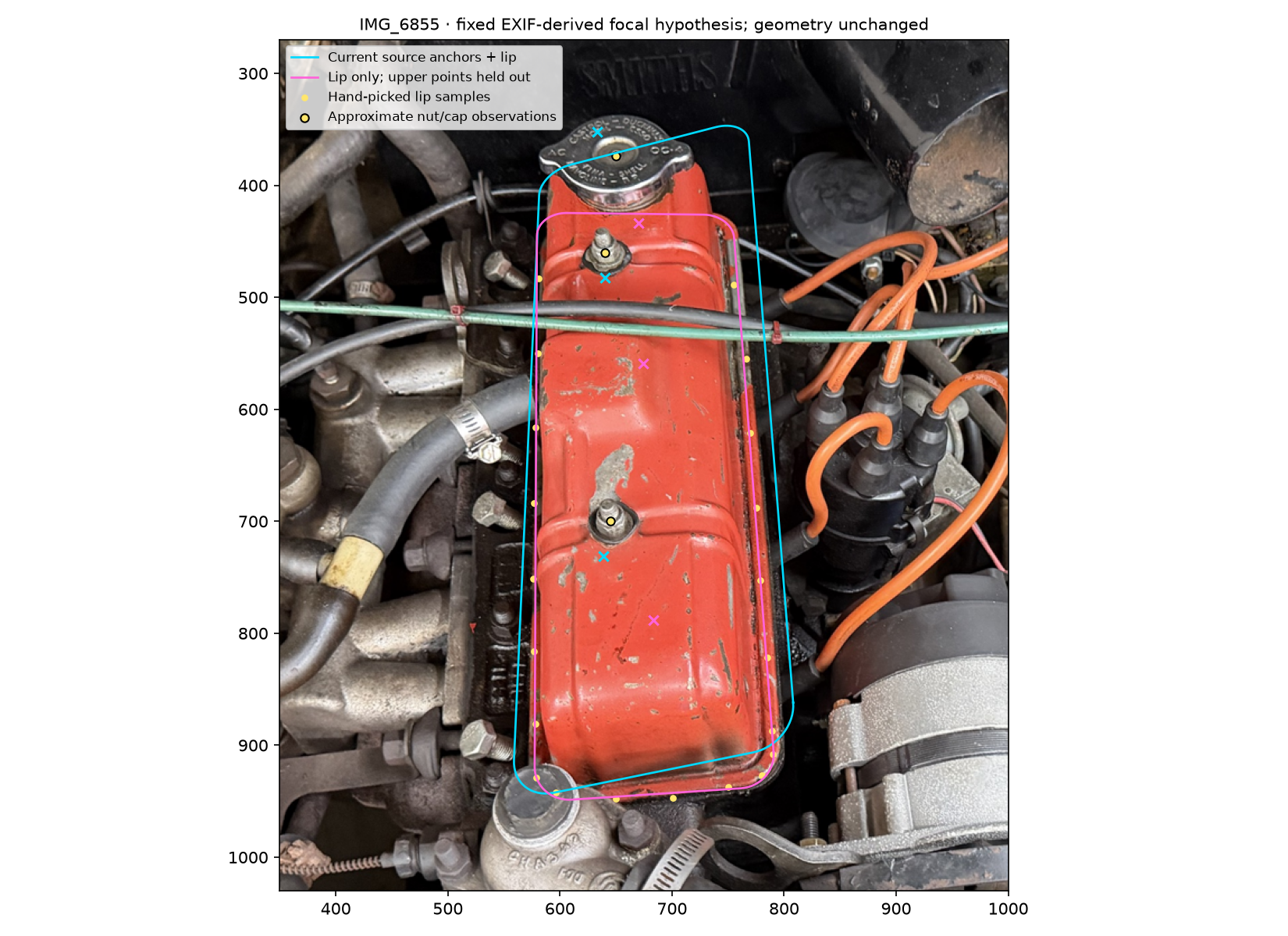
Fitting the current source-cover upper landmarks and lip together gives about 27.43 pixels radial RMS at the upper landmarks and 16.19 pixels at the sampled lip. Fitting the lip while withholding the upper landmarks gives a 2.04-pixel lip residual, but an 89.84-pixel upper-landmark residual. The source cover footprint, height, cap and fastener stations are estimates; photo picking, obscured edges and camera assumptions also contribute. A close outline fit alone cannot validate the component geometry or a common engine/body pose.
This audit changes no native geometry, accepted dimension, fitted identity or engine/body transform. It uses the already supplied captures and requests no repeat photos. The next substantial modeling priority is the coordinated upper front-body profile, while cover datums and common engine/body mounting remain unresolved.
A lower, coordinated front profile
The bonnet and its inner frame, both upper wings, forward scuttle corners and wheelhouse closing faces now share a gentler longitudinal contour. The maximum middle-section reduction is 84.7 mm in the reference model, tapering to zero at the retained rear and nose stations. This is an owner-photo-led construction estimate, not an owner measurement or factory panel dimension.
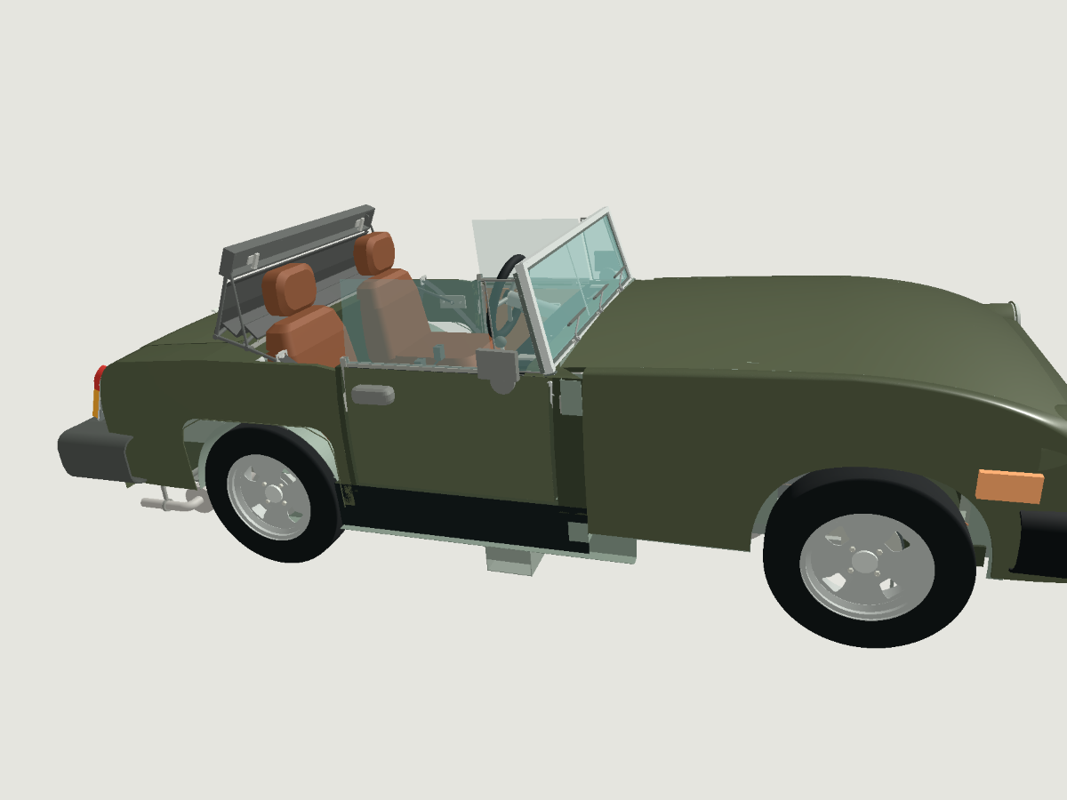
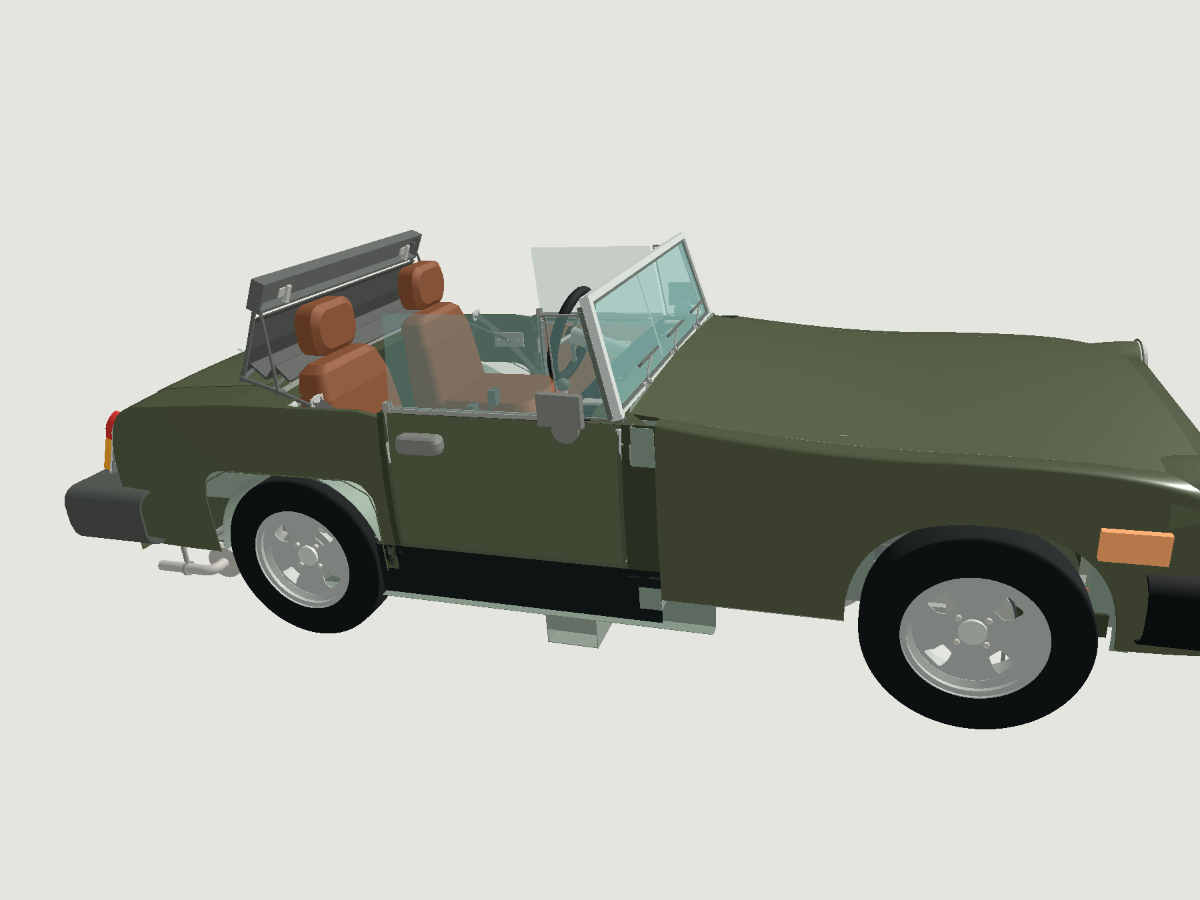
The same manually sampled owner outline improves from 45.97 to 24.41 pixels vertical RMS under the retained wheel camera, and from 30.09 to 10.06 pixels under the EXIF-focal sensitivity camera. Neither camera was refitted to the new shape. Those conditional comparisons support correcting the previous high contour; they do not establish calibrated dimensions or fitted panel registration.
What stayed fixed
The engine/body placement, nominal axle and wheel references, rear body, headlamp axes, wiper and screen datums, hinge pivots and link lengths remain unchanged. The bonnet framework and carried fixing heights follow the new surface. Upper wheelhouse panels blend the correction above the retained wheel-opening roof datum; wheel and lower access openings stay. The pump follows its shared ledge fixing axis as a rigid assembly. The untraced local hose and red battery-loop construction curves are revised without changing their retained endpoints or diameters.
What this helps rehearse
Opening the bonnet exposes the revised overhead skin and framework together with the bay-side obstacles. Select the bonnet, wings, wheelhouse, pump and local hoses to inspect their relationships. Separation remains illustrative: fitted mounting, full foot seating on the estimated ledge, safe support, operating sweep and replacement extraction paths are unverified. Current wing/closing-sheet source overlaps remain explicitly recorded, rather than treated as surveyed seams.
The next substantial priority is the remaining front-body junctions and their engine-bay obstacles, checked against the other supplied views. The common body/power-unit mounting frame remains unresolved.
The apron between screen and bonnet
IMG_6329 shows a broad painted apron carrying three wipers ahead of the windscreen. The earlier model placed their row too far rearward and extended the bonnet over much of that area. The revised native shroud now spans to an estimated bonnet rear station Z 0.32 rather than 0.13 body units. Its center rolls toward the retained side corners and blends to the bonnet’s existing transverse/longitudinal surface at the new seam.
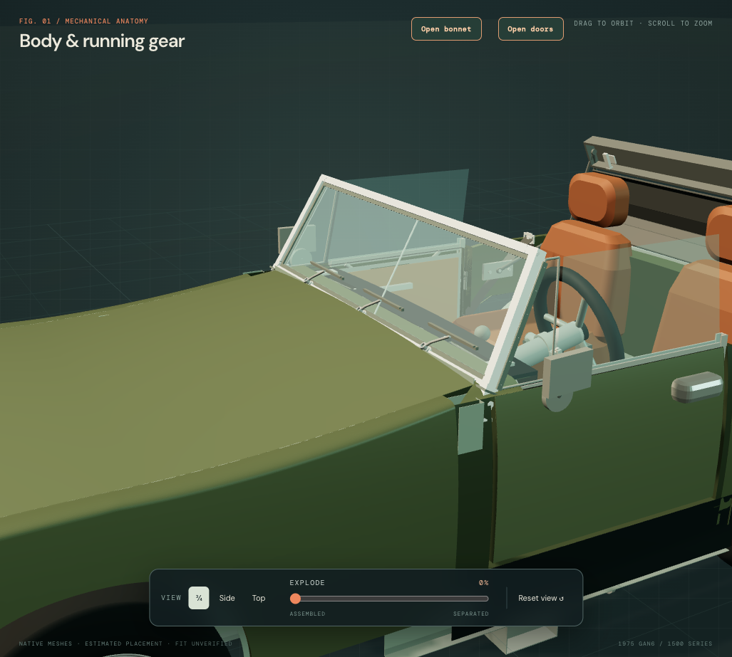
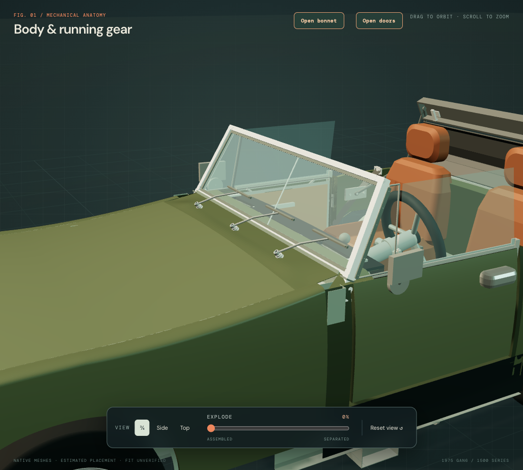
The wiper row moves forward 102.45 mm in the reference model; its X spacing, Y plane and spindle axes stay. The bonnet rear trims forward 160.87 mm. Its rear slotted reinforcement, hollow hinge lands and four fixing roles follow forward. Both complete hinge assemblies move by the same derived 160.87 mm forward and 18.55 mm downward displacement, preserving link lengths and pivot separations. These are construction changes, not owner measurements or a factory body-alignment map.
The motor stays at its old source pose. Revised casing routes meet the relocated wheelbox ports. Static arms now reach back to an estimated blade plane alongside the held windscreen instead of shifting the blades forward with the wheelboxes. A former guessed crossing/grommet is withdrawn from the feed route; the unchanged body aperture is now unassigned. No complete fitted route, live rack engagement, park angle or wiper sweep is verified.
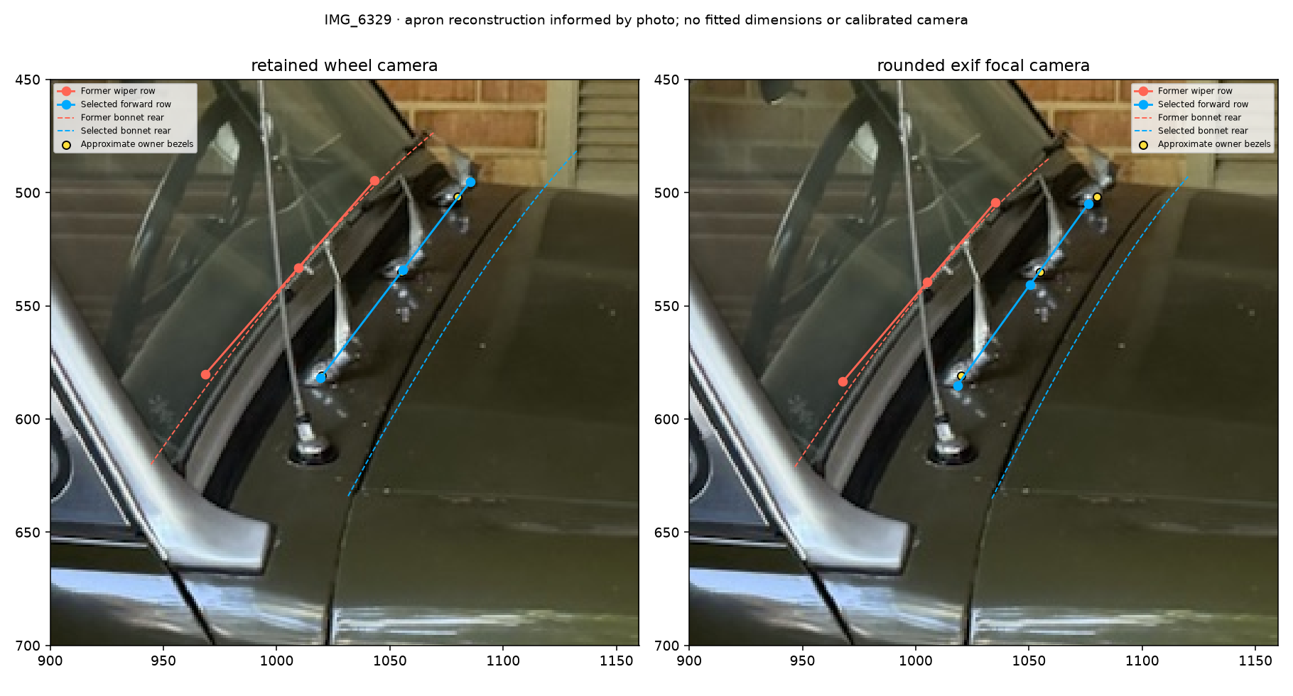
Factory three-wheelbox and North American hinge roles remain distinct from other configurations. British Motor Heritage lists the rubber-bumper CZJ724 scuttle with North America modification required, and separate early/later bonnet comparisons. Neither source supplies the new fitted stations, sections or hinge/body receiver map.
Held surroundings and remaining gaps
Screen/frame, main door glass, rear dash top, side corners, wings, engine/body, lower bulkhead/footwells, wheels and front bonnet closure/stay remain at their prior source frames. Sampled apron/bonnet skin and bonnet/wiper-bezel contacts are zero. The sampled heater case/blower remain clear of the apron. Lower screen/frame-to-apron source contacts remain, including about 16,368 mm³ at the lower rail. Pillar feet, unloaded seals, body receivers and hinge support remain unregistered. This does not establish installed seams, strength, sealing or cold/hot clearances.
Open bonnet exposes the broader fixed apron and the revised rear framework. Five reference opening poses retain mathematical hinge closure; no supported-open condition, complete collision-free sweep, release sequence or verified withdrawal path is established. Do not infer detachable welded panels or repair/cutting instructions from selection or separation.
Wing, door and concealed pillar
The former wing ended 105.833 mm ahead of the unchanged door edge, exposing a broad pillar strip. IMG_6329 and IMG_6341 show a narrow wing/door seam and concealed reinforcement. Both wing skins now extend rearward by 100.833 mm to an estimated 5 mm longitudinal seam. The extension stops at the separate black sill strip. The existing skins forward of the old boundary, wheel openings, arch returns and markers remain.
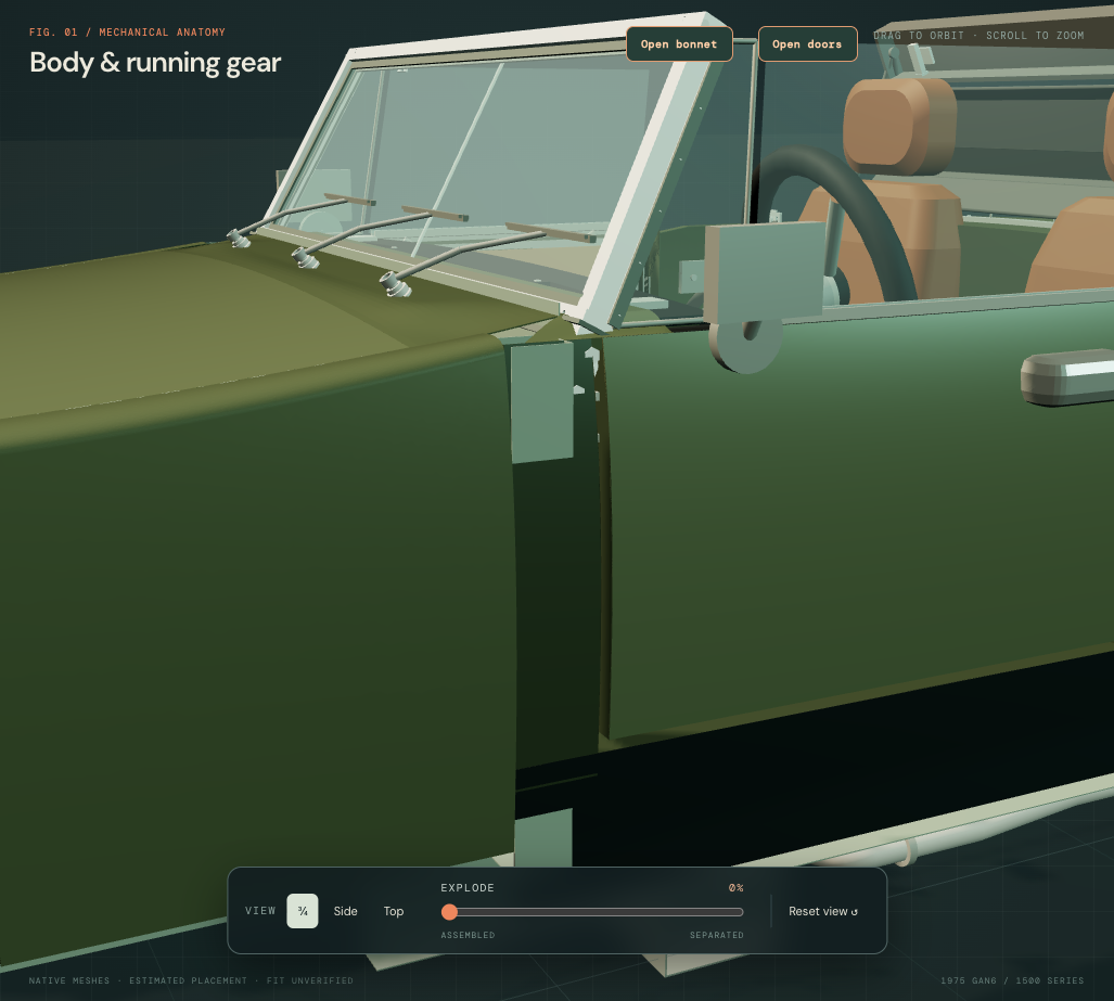
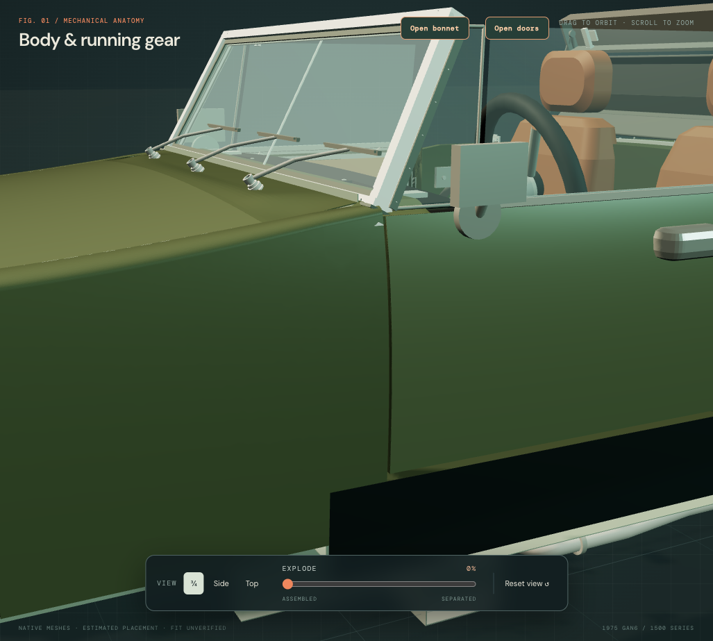
The outer pillar sketch and inner channel now follow the retained body camber 12 mm inboard. This replaces the flat inner wall that projected outside the wing. The 12 mm inset is a construction choice, not a measured clearance. The hinge backing plane and all eight backing-hole axes remain. No hidden fastener, captive plate, weld seam or strength is established.
British Motor Heritage’s body drawing distinguishes the inner supporting structure from the exterior panels; it supplies no fitted dimensions. The photos support panel ownership and visible continuity, not the selected seam width, exact seam inclination or concealed pillar section. The left side mirrors the observed right-side relationship.
Workshop limit: the door still opens in its existing illustrative hinge motion. Neither the new seam nor static nonintersection establishes a collision-free sweep, hinge adjustment, wing release order or a verified replacement path. Common engine/body/suspension registration remains unresolved. The lower sill/footwell and upper scuttle receivers still need reconciliation.
Lower the outer contour, retain the inner threshold
The previous door stopped high above a broad black sill band. The revised reference extends the outer door skin downward by about 59 mm, lowers the outer sill wall and the adjacent wing’s rear boundary, and adds the separate bright moulding seen on this car. The higher inboard sill return, inner door plate, floor, seats, hinge axes and glass hardware stay.
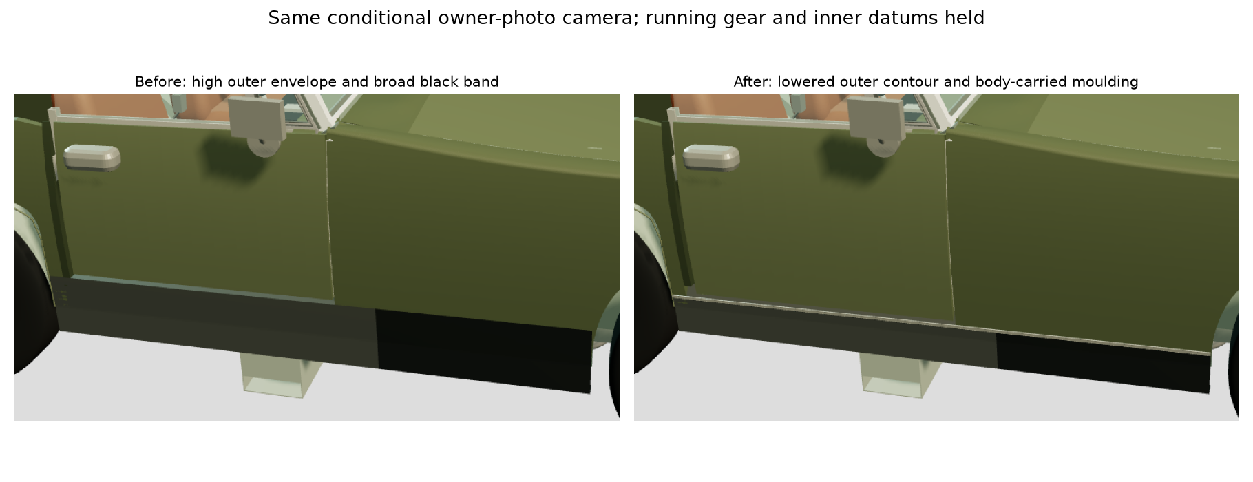
IMG_6329 supplies the closed side context; IMG_6341 shows the moulding remaining on the body below the open aperture. Factory plate235 lists a separate AHA9440 sill-moulding role. The supplier register distinguishes the later lower sill moulding from the earlier upper door mouldings. The model’s generic finisher does not identify this car’s actual part, section, clips or body-hole map.
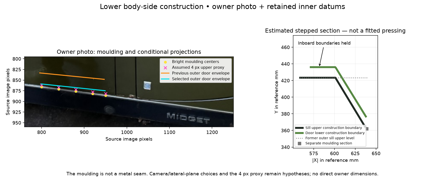
The existing nominal-wheel camera and trial lateral planes put the interpreted upper proxy roughly between 0.41 and 0.45 body units. These alternatives are sensitivity probes, not confidence bounds. Rounded outer sill/door levels of 0.430/0.445 replace 0.500/0.515, while the inboard levels remain 0.500/0.515. The inherited 12.7 mm vertical datum difference is a drawing relationship, not fitted panel clearance. The intervening stepped returns are explicit construction hypotheses; exact metal seams, hidden overlaps, gauges, seals and welded ownership remain unresolved.
The separate rear-open moulding reference has an estimated 8 × 4 mm projected section and no clip holes. It remains fixed when the complete doors open. Ahead of the wing’s changed rear extension, the green/black partitions still occupy the same native material after unifying them for comparison. Their color boundary does not establish a detachable black wing trim or resolve the sill/front-filler ownership.
Checks cover valid positive native solids, mesh/STEP volume agreement, retained inner access material and apertures, zero selected door/sill/moulding intersections in the closed reference, unchanged surrounding source positions and fixed mouldings during illustrative opening. They do not establish actual-car fit, moving-door clearance, structural strength, a jack receiver, repair cuts or verified replacement paths. Existing door-hardware registration gaps remain.
Round the rear quarters into the deck
The previous rear quarters ended at a sharp side-to-deck corner. The existing IMG_6329 and IMG_6341 views show a formed rounded upper shoulder. Both native quarters now carry a continuous rounded transition, and the rear deck meets the same construction boundary. The wheel openings, lower side camber, inboard deck crown and boot aperture remain at their existing references.
Inspect the quarters in the main whole-car model ↗ · Inspect the adjoining deck ↗
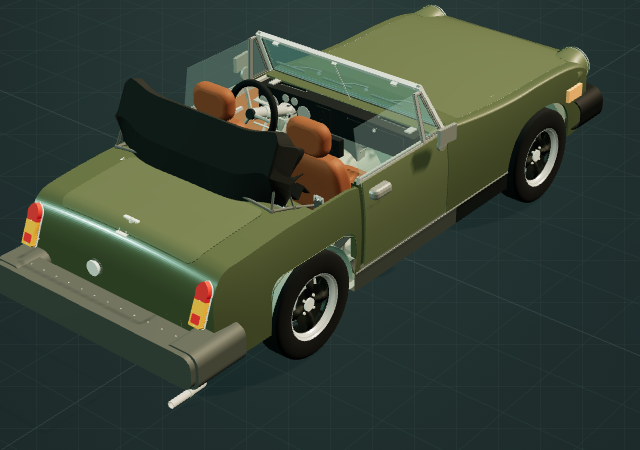
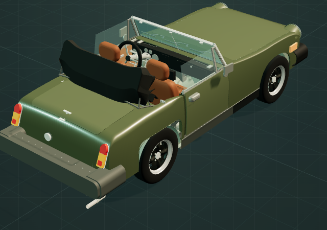
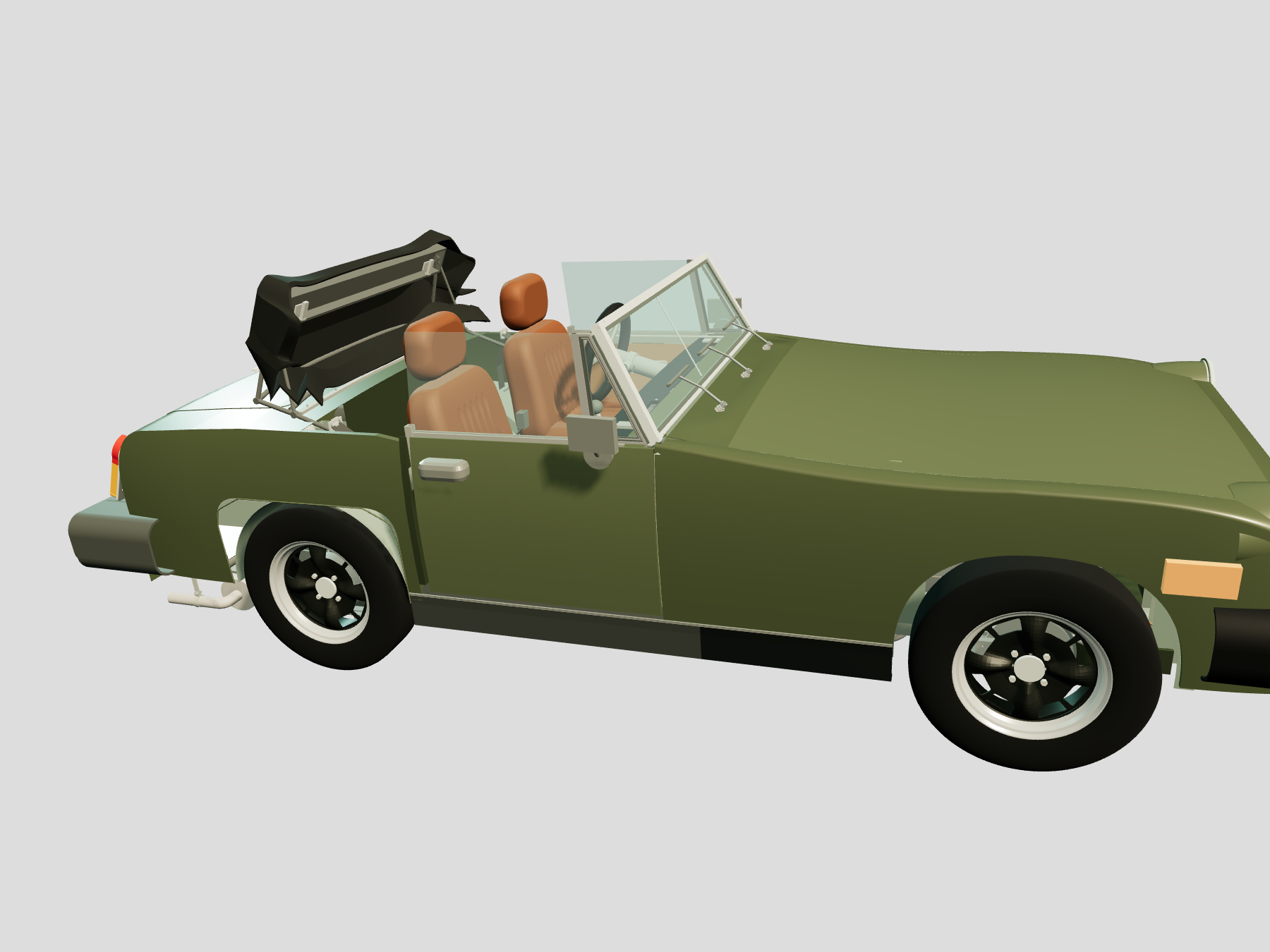
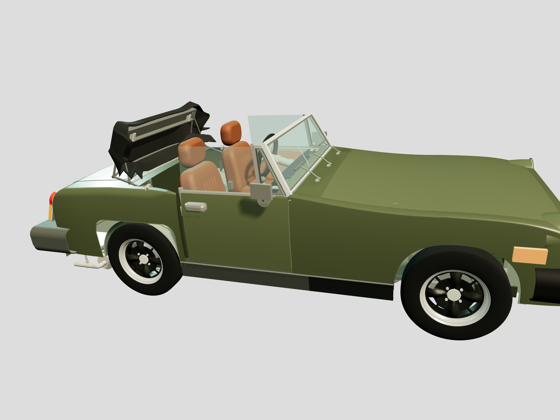
Construction basis: the maximum transverse roll span and side drop are selected as 45 mm in the nominal body frame. This is an estimated curved section, not a measured circular radius. It tapers to estimated 2 mm end rounds near the retained tail and jamb stations. The selected 1.2 mm normal shell offset and 20 mm quarter/deck reference lap are also estimates. The manufacturer distinguishes rear wings, shroud sides, rear deck and wing-to-shroud beading; that supports separate panel roles, not this section, seam location or fitted pressing identity. Opposite-side symmetry remains an assumption.
The new quarters and deck are closed native solids. The rear closing panel and cockpit bulkhead retain their exact meshes; the central boot aperture/lip, lid, wheels, door hardware, hood and mechanical sources remain unchanged. Local native material probes confirm the intended reference lap. A whole-shell Boolean overlap-volume result was inconsistent with those probes and is not used as a contact measurement. Read the native checks and limitations ↗.
Workshop use: these are welded body references. Isolating the quarters or deck explains their relationship; exploded display movement is not a detachable-panel procedure, cut line, weld schedule or verified removal path. Hidden seams, beading attachment, corrosion, bracing, fitted dimensions, strength and panel interchange remain unresolved.
Missing wheelhouse-to-B-post panels
Two broad inner side connections now join the rear wheelhouse and B-post references. The former model had outer quarters and wheelhouses but omitted these panels. BMH lists AHA8014 RH and AHA8015 LH separately for the rubber-bumper application. The first-hand factory assembly photograph BI and supplier photographs show the broad web, curved wheelhouse edge, three open fields and folded front edge.

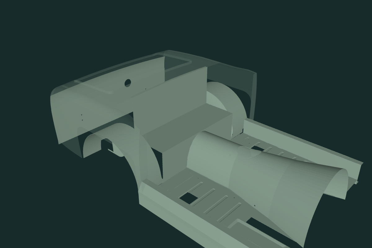
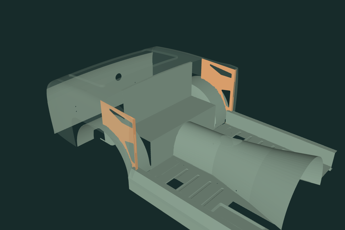
Estimated geometry: panel X=.68 body units; projected 1.2 mm web gauge; 22 mm front return; 8 mm window corner radii. The short lower return reaches the existing floor edge. The curved boundary follows the retained wheelhouse roof; top edges are selected 8 mm below the prior quarter profile. All positions, shapes and mirrored symmetry remain construction estimates. Owner IMG_6329/6341 supplies exterior/doorway context, without exposing this bare panel or establishing hidden dimensions.
Each new native panel is one connected solid with three bounded web openings and an open front-fold slot. The two outer-quarter meshes and original native volumes remain; wheelhouses, floors, seats, hood, belts, B-post surfaces and mechanical sources stay. Native material, section and surrounding-source contact checks report drawing contacts and remaining overlaps. No source is moved or cut to erase a contact.
Workshop connection: these are welded body references, fixed during inspection separation. Isolating a panel explains its relationship to the wheelhouse, sill and door aperture. It does not establish body strength, bracing, cutting or welding instructions, repair suitability or a verified replacement path. The visible supplier captive latch assembly and small fixing holes are not transferred to an unverified map; actual striker receivers, hidden reinforcements, seam ownership and loaded clearance remain unresolved.
Review the screen in the complete car
The current exterior review identifies the screen outline as a supported broad correction: original donor-frame photographs show the lower arch and rounded upper glazing corners missing from the previous reference. These matched renders use the unchanged IMG_6329 wheel-based camera. The car is not moved to improve the comparison. Glass compound curvature, camera uncertainty and fitted body relationships remain unresolved.
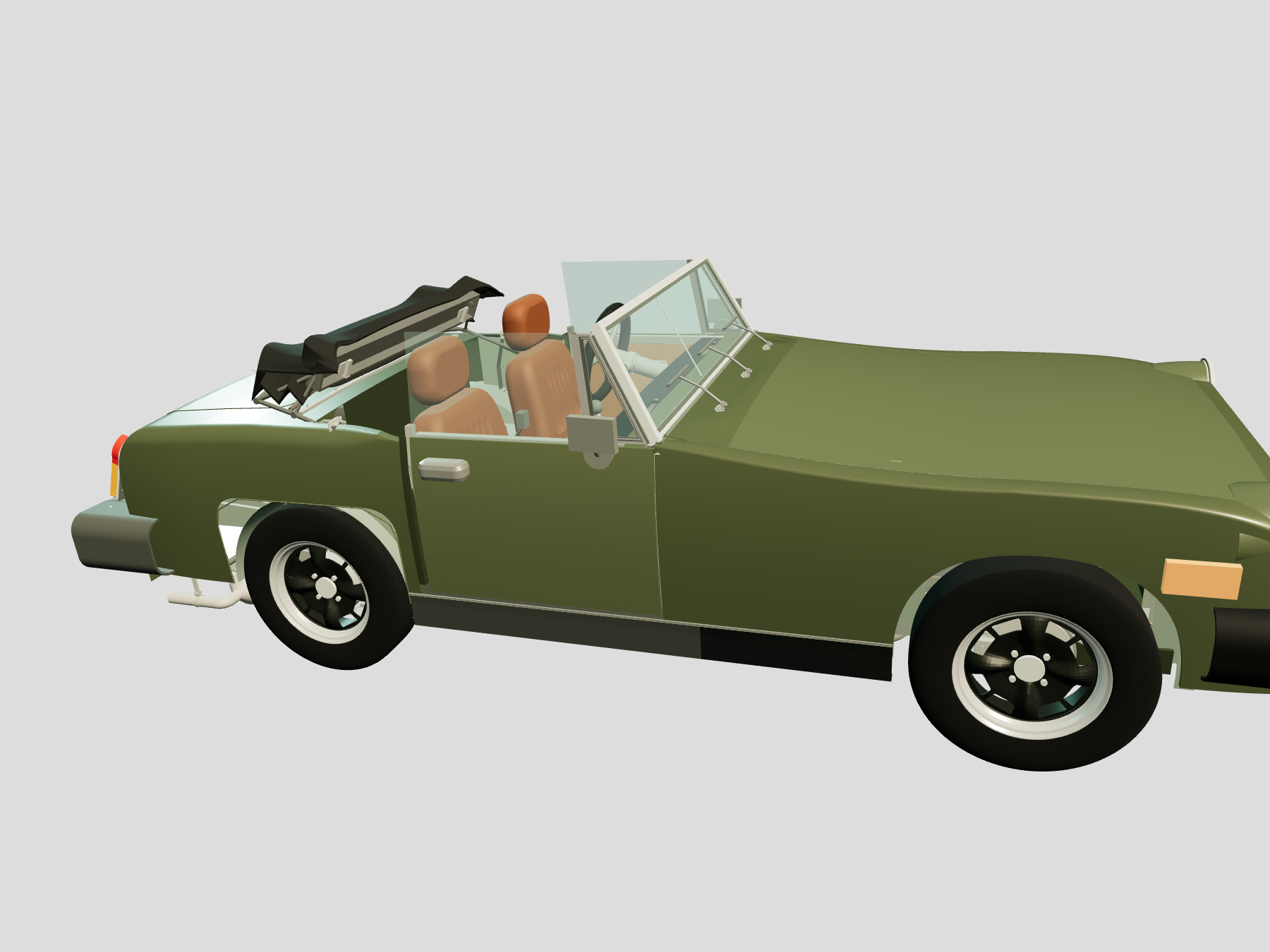
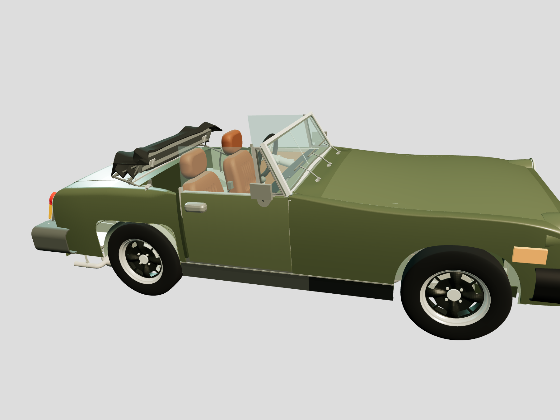
Inspect the screen and its retained mounting limits ↗. The assembly comparison makes the lower arch clearer than this oblique full-car view. No numerical fit to the new pane outline, body receiver or verified replacement path is claimed.
Front structure: a dimensional registration concern
A direct review of the earlier AKD4021B factory horizontal-alignment drawing, Section R.16 / printed R.18, raises a substantial concern about the current transverse construction. Its footer covers Sprite Mk II/III and Midget Mk I/II; the rear-spring arrangement is earlier than this car. These are comparisons to investigate, not accepted 1500 specifications or measured errors in the owner car.
| Feature | Current CAD | Earlier printed metric | Arithmetic difference |
|---|---|---|---|
| A–A: front inner-pivot pair | 609.6 mm | 465.2 mm | 144.4 mm |
| B–B: rear inner-pivot pair | 609.6 mm | 465.2 mm | 144.4 mm |
| C–C: inside frame side-members | 546.1 mm | 279.4 mm | 266.7 mm |
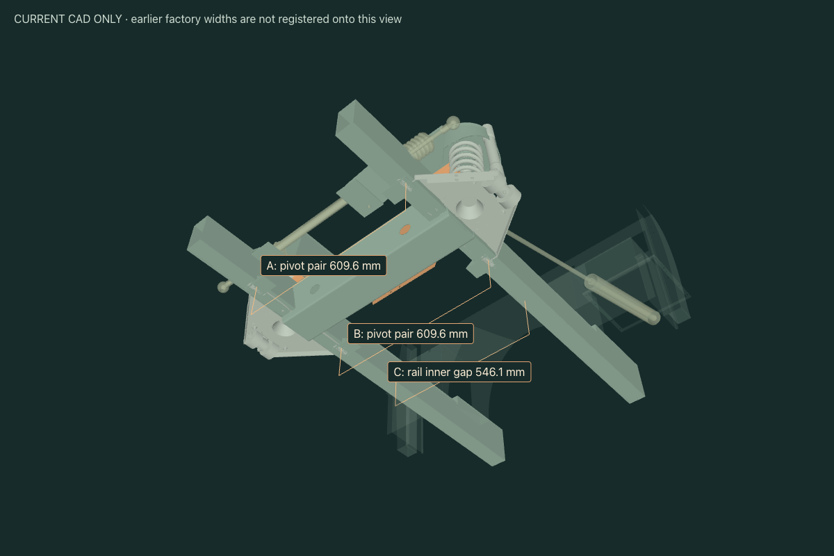
The audit checks the four receiving bores and adjacent material in the STEP model, confirms that wishbone nodes share those axes, and samples the rail sections at three longitudinal stations. It holds the body register and ten neighboring JSON/STEP files. This verifies what the current model contains; it does not verify the actual car.
The drawing appears to print 18⅜ in beside 465.2 mm for A/B; converting the inch value gives 466.725 mm. Its D–D pair also disagrees between units. No value is silently corrected or averaged. The applicable 1500 horizontal and vertical drawings, point definitions and original owner datum record are needed before a coordinated change across rails, pickups, wishbones and supports. Moving the engine or an isolated bracket to erase an overlap would not establish the common frame.
The accessible 1500 manual cover is AKM4071/B and includes North American material. The retrieved introductory/engine sections do not expose the body drawings around printed pages 186–187; later guessed section URLs were unavailable. The separate 76-C-2 bulletin index applies to MGB, so it supplies no Midget dimensions. Geometry and the whole-car comparison remain unchanged by this review.
Current whole-car comparison
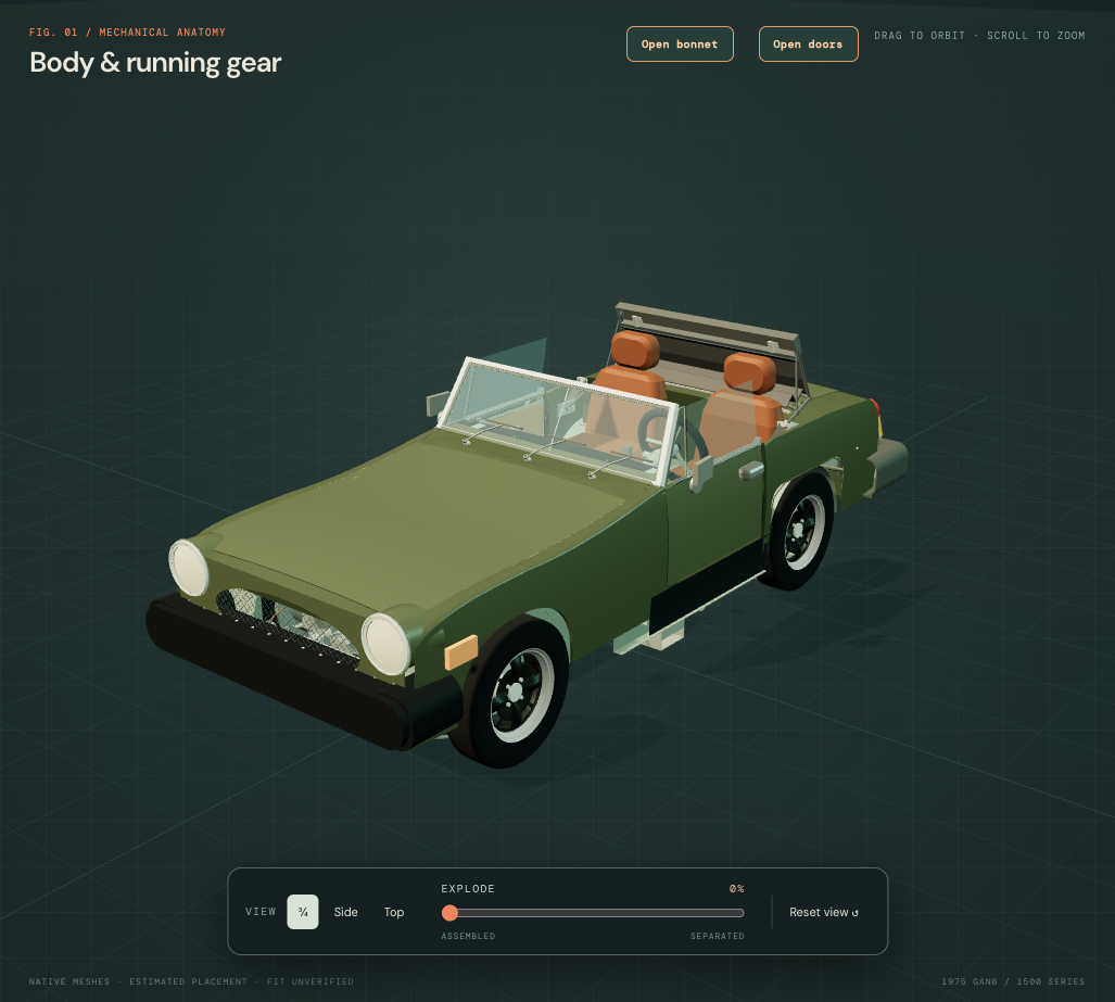
This render includes the lower door/sill contour and separate mouldings, together with the native door shells, rounded seats, gathered hood and compact rear gearbox support. The two images use the existing wheel-derived camera hypothesis. No model parts were moved to make this comparison. Image coordinates and nominal axle references constrain the view; they do not survey the car.
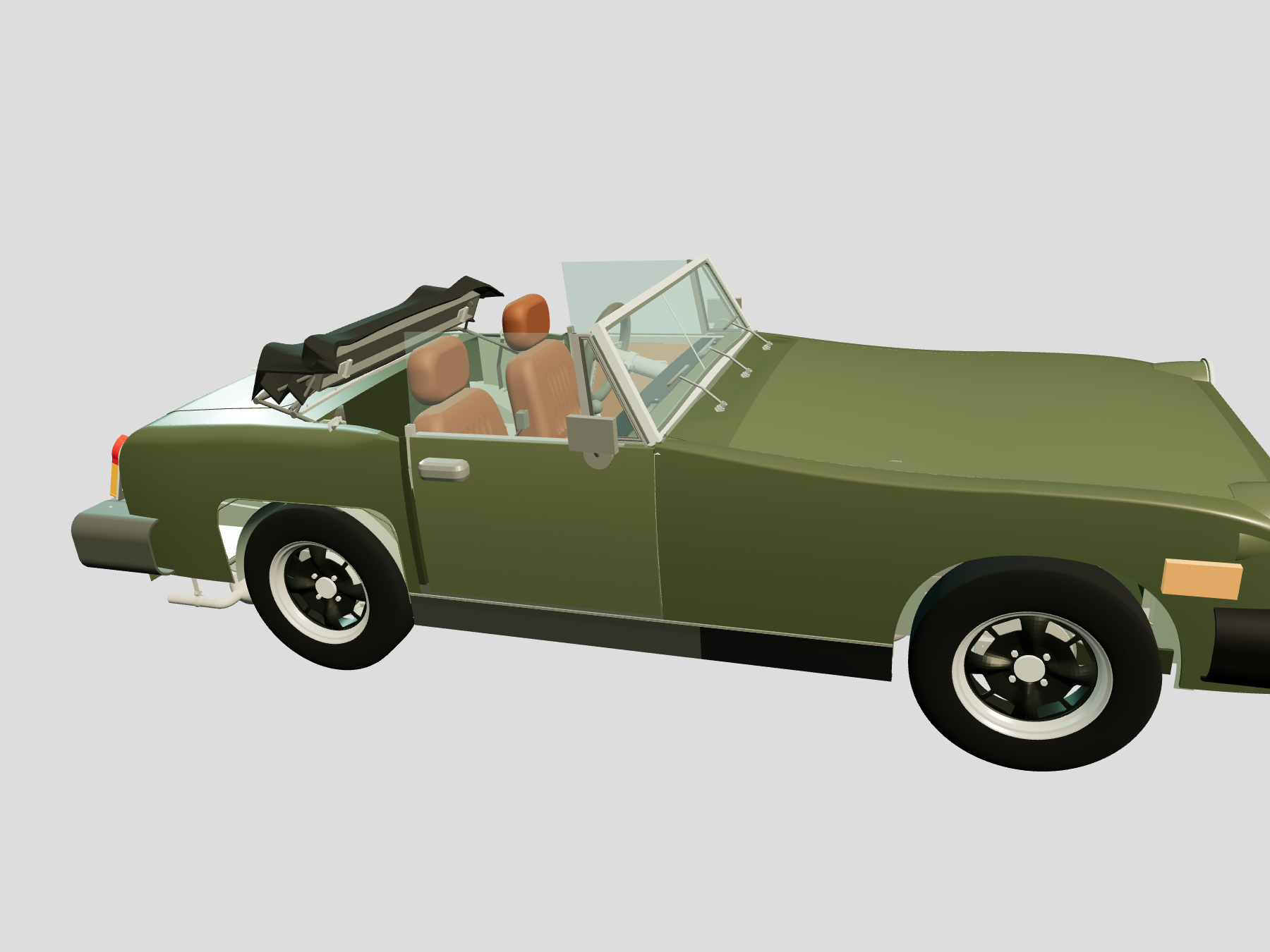
The comparison makes the remaining work visible: cabin/glazing and rear soft-top proportions need further reconciliation, body seams remain approximate, and the installed engine/body frame is still unregistered. IMG_6341 exposes more of the header, but occlusion and viewpoint prevent establishing a different parked state. Reflections are not panel seams and occluded contours are not measured dimensions. The next geometry priority is the largest discrepancy supported across the existing views, rather than further hidden-detail refinement.
Original 1975 dimensions and the low exhaust reference
The original British Leyland bulletin 75-G-2, page 2 supplies a direct 1975 specification comparison. These values describe the factory reference, not measured dimensions of this car. The current viewer was checked assembled, with doors and bonnet closed and the hood parked; all 84 native sources loaded.
| Comparison | Factory reference | Current model |
|---|---|---|
| Wheelbase | 2,032 mm | 2,032 mm anchor spacing |
| Pressed-wheel tracks, front / rear | 1,182.6875 / 1,143 mm | Same nominal anchor spacings |
| Overall length | 3,581.4 mm | About 3,581.4 mm between bumper extrema |
| Pressed-wheel overall width | 1,393.825 mm | 1,397 mm bumper span; about 1,465.45 mm including door mirrors |
| Overall height | 1,225.55 mm; hood state not stated on this page | About 1,125.39 mm from mesh tyre bottoms to screen top, hood parked |
| Ground clearance | 82.55 mm | Estimated exhaust cross-box only 8.47 mm above the analytic tyre-bottom plane |
The width table does not define every inclusion boundary. The compiled workshop reading of 1,362.075 mm and older handbook height transcription of 1,130 mm remain separate records. Neither overall height nor width supplies the internal rail or pickup dimensions needed to resolve the earlier chassis concern.
The native STEP cross-box lower face is Y=55.03333 mm and the longitudinal chamber lower face is Y=62.65333 mm. The current estimated wheel center and unloaded tyre radius put an analytic tyre-bottom plane at Y=46.56667 mm, leaving only 8.46667 and 16.08667 mm respectively. Actual rendered mesh bounds independently expose the same low assembly; mesh tessellation shifts the sampled tyre plane by about 0.018 mm. Front coupling and downpipe references are also low.
This is a drawing conflict within the estimated model, not actual-car ground clearance or proof of interference. The bulletin does not establish the car's loading, tyre state, fitted exhaust or component poses. Earlier local routing lowered the front coupling by 93.13 mm relative to its prior scaffold to pass beneath the estimated gearbox; that did not resolve the complete frame. Do not raise only a silencer, shrink tyres or move a ground plane to obtain the published clearance. The next correction needs the engine, gearbox, body, exhaust and supports reconciled together against existing evidence.
No geometry or existing assembly transform changes in this audit. Displayed separation remains illustrative; loaded clearance and replacement paths remain unverified.