From heater
toward the cabin.
The cabin reference now separates paired demister elbows, hoses, North American nozzle comparisons and footwell outlet doors around an estimated distribution chamber. The supply boundary remains open: the heater outlet and body crossing are not registered together.
Preserve the observed open intake
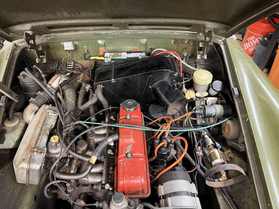
The MGOC catalog lists CHA290 heater intake hose and AHA8786 wheel-arch clip as 1500 comparisons. Neither is imposed as fitted. The existing corrugated intake/air-cleaner references on the other side retain their own unresolved identities; they are not reassigned to the heater. IMG_6341 supplies cabin context but does not survey the hidden air distribution.
Inspect the cabin branches
The hollow chamber has an open top supply boundary, two demister branch mouths and separate footwell mouths with outlet-door envelopes. The paired hoses lead to broad slotted nozzles near the windscreen base. All locations, sections, flange holes, door poses and chamber shape are estimated. The chamber represents a body-distribution hypothesis; it is not an identified removable box.
Factory relationships and market differences
Factory PDF p. 280 lists two AHH8394 demister hoses. PDF p. 281 separates 14G3499 elbows, North American AHA8565 RH / AHA8566 LH nozzles and 13H59 heater outlet-door architecture. The non-North-American 14A1162 nozzle is a different catalog branch. None identifies the fitted hidden pieces or supplies modeled dimensions.
Keep the supply gap explicit
No duct joins this cabin chamber to the engine-bay heater. The existing heater case, support ledge, bulkhead and dashboard are not moved or cut to manufacture a connection. The exact casing outlet, body aperture and intervening chamber/duct geometry remain unresolved. The reference can expose the cabin branches without establishing a complete air circuit, sealing or airflow.
Nozzle and door offsets expose their shapes; they are not verified withdrawal directions, operating door travel or a repair sequence. Scuttle attachments, wiring interference, mounting access, blower performance, loaded fit, actual hose lengths and verified removal paths remain unmodeled or unverified. Native millimeter scale does not turn estimated body coordinates into surveyed fitted positions.
Separate CAD reference
Construction checks cover valid solids, STEP round-trip and open demister/nozzle mouths with material around the chamber openings. They do not verify fitted clearance or a complete operating circuit. The heater and core engine exports are unchanged.
The heater lower outlet/base reconstruction now opens the former closed case bottom and adds a separate base seal and six mounting roles. The body platform and this cabin chamber retain their independent geometry. Most of the reference outlet projection still meets body sheet; a full common aperture and supply route remain unresolved. No connecting duct or body cut is inferred from their proximity.
Fascia/nozzle registration
The former floating nozzle pose is superseded by the shared upper-dash construction below. It remains an estimated connection, with no fitted survey or verified heater supply path.
Outlets through the upper dash reference
Two hollow North American end-inlet nozzle comparisons now sit beneath a new rear dash-top pressing. Two slots and four fixing passages continue through that pressing and the existing fascia padding. The paired upper hoses now end in open cuffs around the nozzle sleeves. Four smooth fixing envelopes show the attachment relationship.
The factory shroud plate shows two long openings; the heater plate distinguishes AHA8565 RH / AHA8566 LH for North America, the different 14A1162 branch, and four PTP6036 screws. These establish roles and quantity. The mirrored end-inlet shapes, outboard inlet interpretation, contours, slot positions, four axes, hole and screw sizes, hose bends and cuffs are all construction estimates. They do not identify the installed hidden pieces or provide a drilling template or hardware specification.
The added pressing has an estimated 1.5 mm projected vertical gauge. Each estimated slot is 187.96 × 25.4 mm; its oversized opening around the nozzle mouth is a drawing construction, not a measured seal clearance. The broad upper hose curves replace a self-intersecting provisional spline; their bend radius is not a hose specification.
Shared openings and axes connect the estimated sources. They do not verify hidden body joints, upper-hose clearance against the glovebox/column, compression, airflow or access to the fixing heads. The heater-to-body supply crossing remains open, and the owner-photographed heater intake stays open. Factory parts plates do not establish a release order, tool access or withdrawal path. Viewer separation is illustrative.