Inside and around
the heater.
The hollow casing now separates from its rear cover, matrix, seal, motor and fan. Two local hose forms and a water-control tap/elbow/bracket comparison add the neighboring connections needed to inspect this assembly. Remote hose destinations remain open evidence boundaries.
Inspect the cabin air branches ↗ for the new independent demister/footwell reference. IMG_6856 shows the heater intake neck open at capture time; no factory intake hose is imposed as fitted. The heater-to-body air supply remains unregistered.
Inspect the service architecture
The original upper casing, separate rear cover and air/water neck geometry remain. The whole-car case now adds the lower outlet and mounting-base reference described below. The whole-car viewer replaces the combined casing mesh with a separate casing and rear-cover reference, then adds estimated internals. The detailed core engine export remains unchanged. General separation offsets the cover, core/seal and motor/fan for inspection; it does not establish their actual withdrawal directions, a service order or a supported working state.
Open lower outlet and mounting base
The former heater reference had a closed bottom and no lower mounting flange. Factory plate280 shows the formed lower base and lists six heater-to-platform screws and washers for the GAN6 unit. The supplier’s 1500 heater description distinguishes a case-to-platform seal. These establish component roles, without identifying the actual underside dimensions or fitted seal.
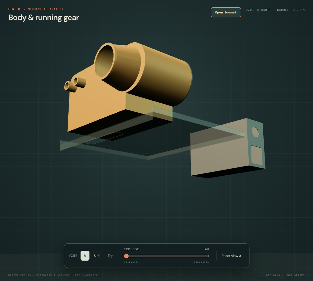
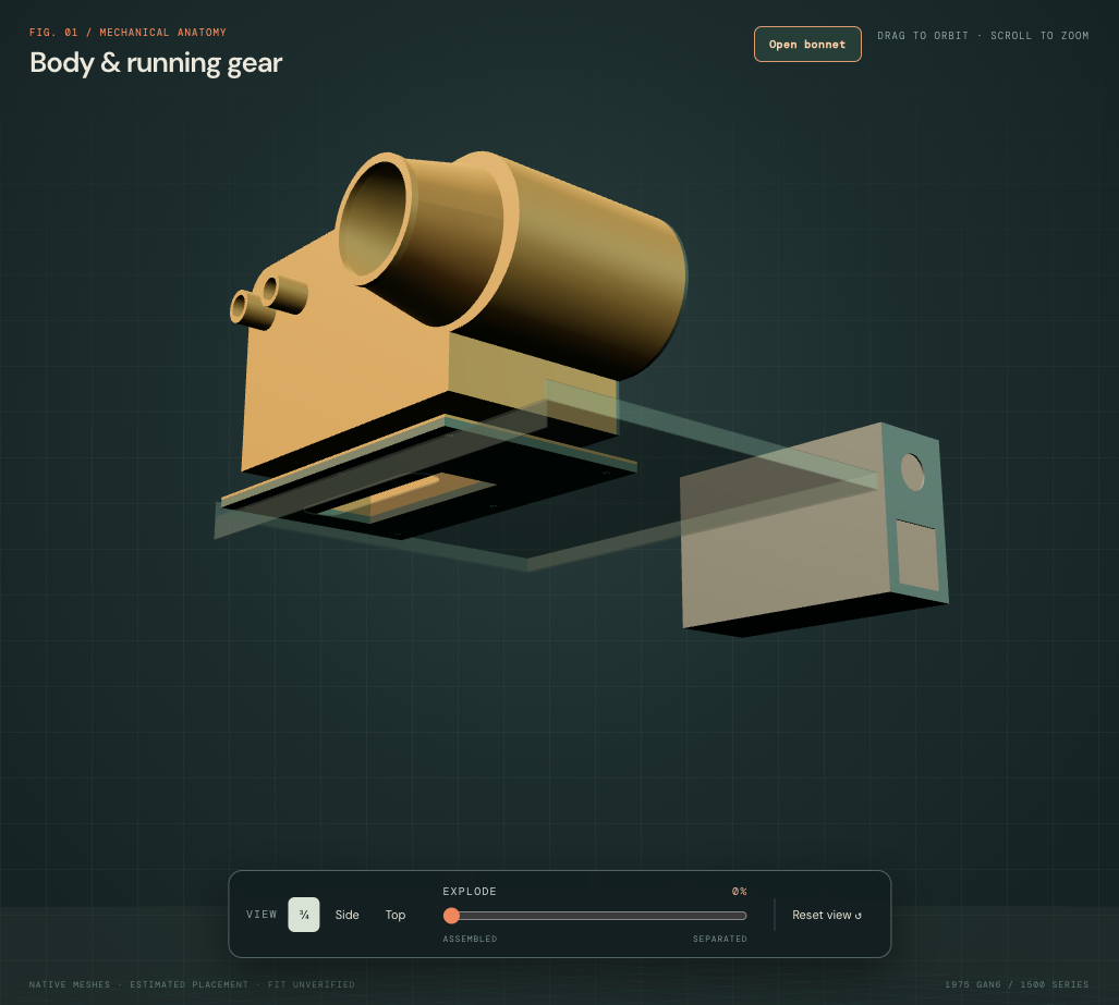
The estimated throat follows the source matrix region, independently of the platform’s unassigned oblong feature. A 20 mm lower pan, 2 mm flange and 160 × 50 mm throat are construction choices. The separate 6 mm foam-seal comparison and six smooth screw/washer roles share that estimated footprint. All dimensions, bore positions, thread/engagement and material properties remain unmeasured. No body receiver holes are added.
| Relationship | Current source result | What it establishes |
|---|---|---|
| Case interior / lower throat | The former bottom cap is opened; adjacent pan wall remains. Six flange bores have adjacent material. | An open reference outlet and mounting roles, without validated air behavior. |
| Unloaded seal / platform top planes | 2.41 mm drawing-plane difference | Independent unmeasured frames still have a gap; this is not fitted clearance or loaded sealing. |
| Outlet projection / platform sheet | About 7,122 of 8,000 mm² still project onto solid body sheet. | The platform slot is not identified as the outlet. No body aperture or connecting duct is fabricated to complete the airway. |
| Case / tunnel reference | 342.57 → 550.88 mm³ source contact; new seal/tunnel contact 627.36 mm³. | The lower base adds a surrounding obstacle and exposes unresolved body/heater registration. |
The main case above the lower modification, rear cover, necks and eleven other existing heater groups retain their source geometry. Platform, cabin chamber, bulkhead, battery-area equipment and engine source stay. The owner-photo-led 80 mm rearward heater placement is retained. IMG_6856’s open fresh-air neck remains open; it is distinct from this lower cabin-supply reference.
No complete heater-to-cabin airway, common body aperture, actual receiver threads, supported lift or fitted replacement path is established. General separation exposes the seal/fixing roles for inspection; it supplies no safe coolant, electrical or mounting-release order. The independent engine-only export keeps its earlier casing reference.
What the owner photographs establish
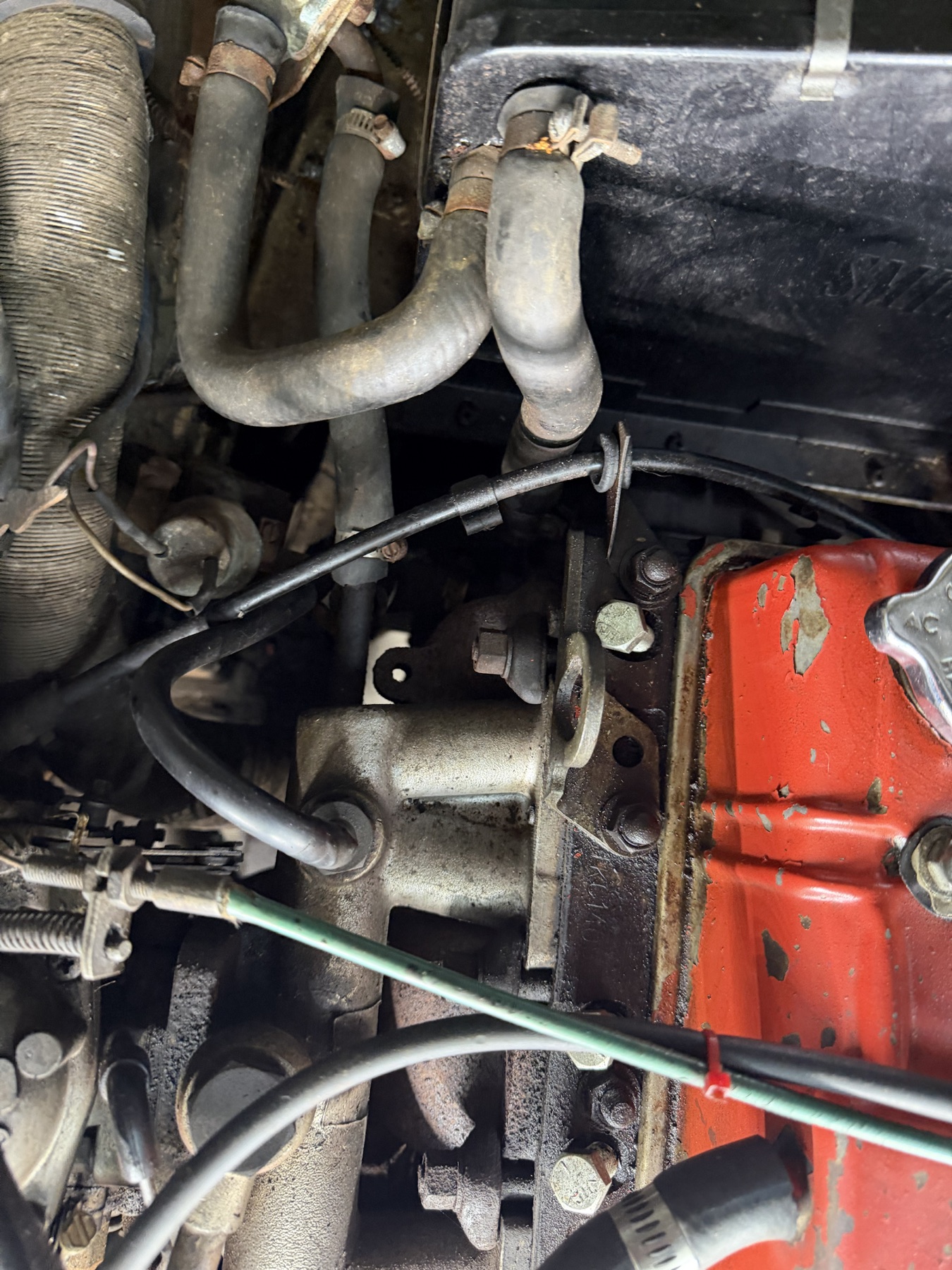
IMG_6890–6892 show the paired connections, one broad lateral hose bend, one down-turn, mixed clamp forms and the green tap nearby. They do not show a complete coolant circuit or calibrate any fitted dimensions. The new hose A reference meets the tap-side comparison axis; that is a drawing relationship, not proof of the hidden fitted join. Hose B and the elbow-side hose each end before their untraced remote destination. Neither is assigned a verified supply/return direction or catalog hose identity.
Keep factory variants distinct
Factory Parts-1977, PDF p. 280 lists the 1500 CHA345 heater, 37H8818 matrix, 37H4583 motor/mounting plate and six platform screws. Those are architecture comparisons, not fitted identifications. The original case profile and all internal envelope dimensions remain estimates; the fin and blade counts are drawing choices.
The same plate distinguishes North America except California CHA352 control-tap/manifold plumbing from other-market hoses and the California bypass/automatic-choke branches. The MGOC supplier catalog separately illustrates the 1500 tap/elbow/footwell-bracket architecture and water-pump return. Earlier 1275 radiator-return topology is not imposed on this car. No hose, valve, gasket or cable is selected for purchase from this reference.
The Heritage publication register identifies AKM3267 as the North America 1975 workshop manual. Its heater instructions have not yet been reconciled to this fitted assembly; the current model does not encode a verified factory replacement sequence.
Return-pipe comparison
The branched pipe, union and hose comparison exposes additional factory connection roles. Its pose intersects block/exhaust references and remains unregistered. It does not resolve either existing untraced hose boundary or establish an installed coolant circuit.
The platform support-extension comparison now adds the shared manufacturer drawing’s lateral wing, downstanding leg and raised ear. The original platform and heater geometry stay. Those features do not identify the fitted support or resolve the body/cabin opening, loaded seating or receiver positions.
Use the surrounding obstacles
The whole-car layout now places the complete heater and local controls 80 mm rearward of the inherited engine-relative drawing. IMG_6891/6892 show it closely ahead of the battery; the rounded shift is a layout estimate, not a measured position. The model-plane gap falls from about 94 to 14 mm, which does not establish actual clearance. The original upper case dimensions and orientation remain; the added lower base uses the same pose. The battery, shelf, bulkhead and engine stay in their independent reference frames. Heater B is now 80 mm from the old return-pipe comparison endpoint; no joining hose or body mounting is invented. Dedicated engine CAD and the separate source STEP retain their original source pose.
Compare the heater with the battery behind it, shelf beneath it, bonnet hinges, rocker cover, distributor leads and existing hoses. The case stays fixed while the inspection view separates the internal references. The tap bracket remains separate from the valve and elbow, but its body mounting and contact are unregistered. The model establishes no loaded support, drain/disconnection operation, spring or electrical release, tool access, lifting path or verified replacement procedure.
The second internal neck stops at a short straight boundary; its hidden route to a header is not reconstructed. Hidden water passages, actual core construction, motor orientation/wiring, seal compression, valve internals and actuation, complete hose routing, pressure/flow, airflow, thermal performance and operating clearances are unverified. Apparent intersections or gaps against body and engine geometry remain model results. Use the applicable complete workshop procedure after identifying the fitted assembly.
Native files and construction checks
The revised builder checks valid solids and STEP round-trip and records limited static internal/casing intersections. The lower outlet/base changes occupied volume; the original upper case and eleven other existing assembly groups remain held. These checks validate reference construction, not fitted seating or full surroundings. Open water/air axes and local hose-end locations are checked separately in the viewer.