Behind the
Smiths heater.
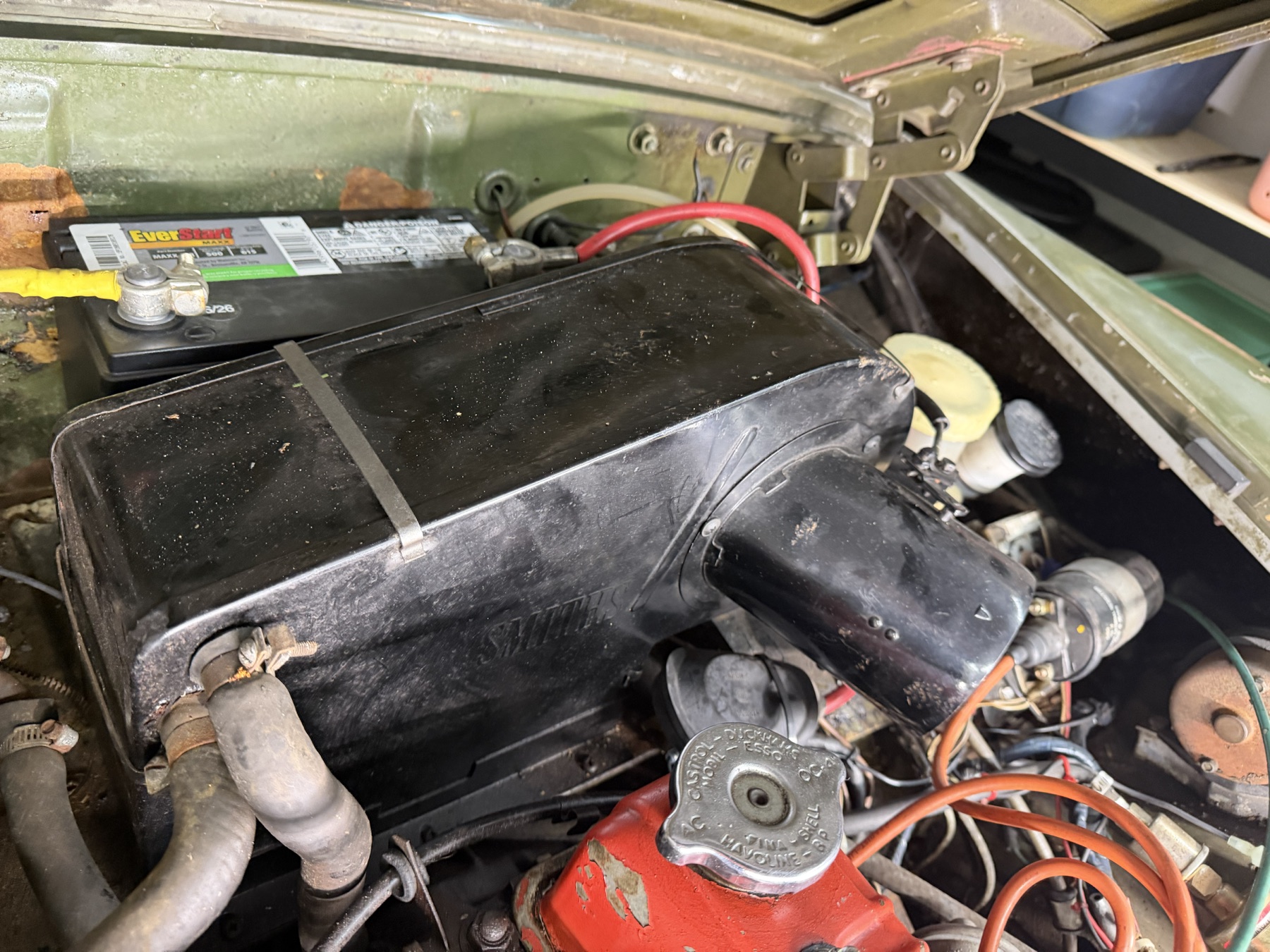
The battery is a substantial obstacle at the back of this engine bay. IMG_6892 shows an EverStart case behind the heater, two terminal clamps and short red and yellow-covered cable sections. The lower support and hold-down are largely hidden.
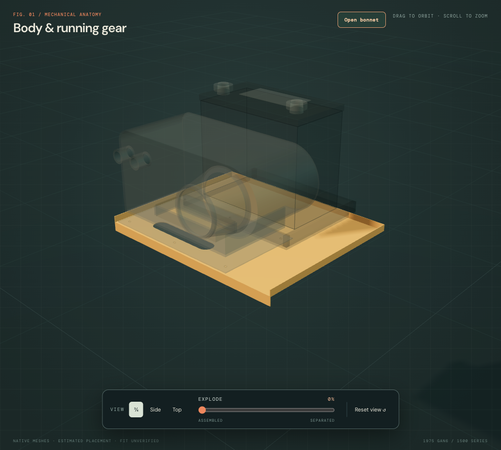
Inspect the modeled relationships
The black case and terminal cues represent visible owner evidence. Full-resolution IMG_6891 exposes the MAXX-51R model field obscured in IMG_6892. The Walmart MAXX-51R listing gives 9.31 × 5.06 × 8.69 inches, mapped to 236.474 mm cross-car width, 128.524 mm depth and 220.726 mm overall height. These are catalog dimensions, not owner measurements or a verified production-specific drawing. The model includes an estimated 20 mm post projection within the overall height. Case/lid split, terminal spacing and clamps remain estimates. Cable colors reproduce appearance only; the model assigns no polarity or complete circuit destinations.
The separate formed-platform comparison replaces the old broad thick shelf. The tray, packing, angle bar and hooked rods explain possible support and retention relationships. Their shapes, positions, hidden attachment map and installed presence remain unverified. The tray and retention comparison retain their previous dimensions; they are not resized to manufacture fit with the narrower catalog battery. The heater retains its source dimensions, but its whole-car placement is now independently revised from the inherited engine-relative drawing; these references do not solve fitted body/heater registration.
A formed platform, not a thick shelf
The British Motor Heritage drawing and application table distinguish CZJ174, the later integral-fan heater platform, from complete BMH8010 support and earlier BMH8019 support. These are catalog comparison roles, not fitted identities. The model replaces its broad 754 mm-wide, 15 mm-thick shelf slab with a 390 × 315 mm formed-sheet reference at an estimated 1.2 mm gauge, retaining the previous upper support plane.
Edge returns and an open oblong-slot interpretation follow the drawing architecture; their dimensions, orientation and installed position remain estimates. The new shared-illustration wing/leg/ear references remain unmeasured. Actual welded attachments, heater base/body aperture, loaded seal and cabin-air join remain unresolved. The platform is not moved into contact with the heater or battery to imply loaded support. Tray, hold-down, battery, heater and bulkhead retain their independent geometry and positions. This is neither a fabrication template nor a verified repair/removal sequence.
Support wing, leg and raised ear
The manufacturer’s F19/F20 drawing and application table distinguish the CZJ174 platform, BMH8010 later integral-fan complete support and BMH8019 earlier separate-fan support. F20 is a shared illustration. Its lateral extension, downstanding leg/foot and raised ear support architectural comparisons; they do not identify the exact shapes, orientation or attachments fitted to this car.
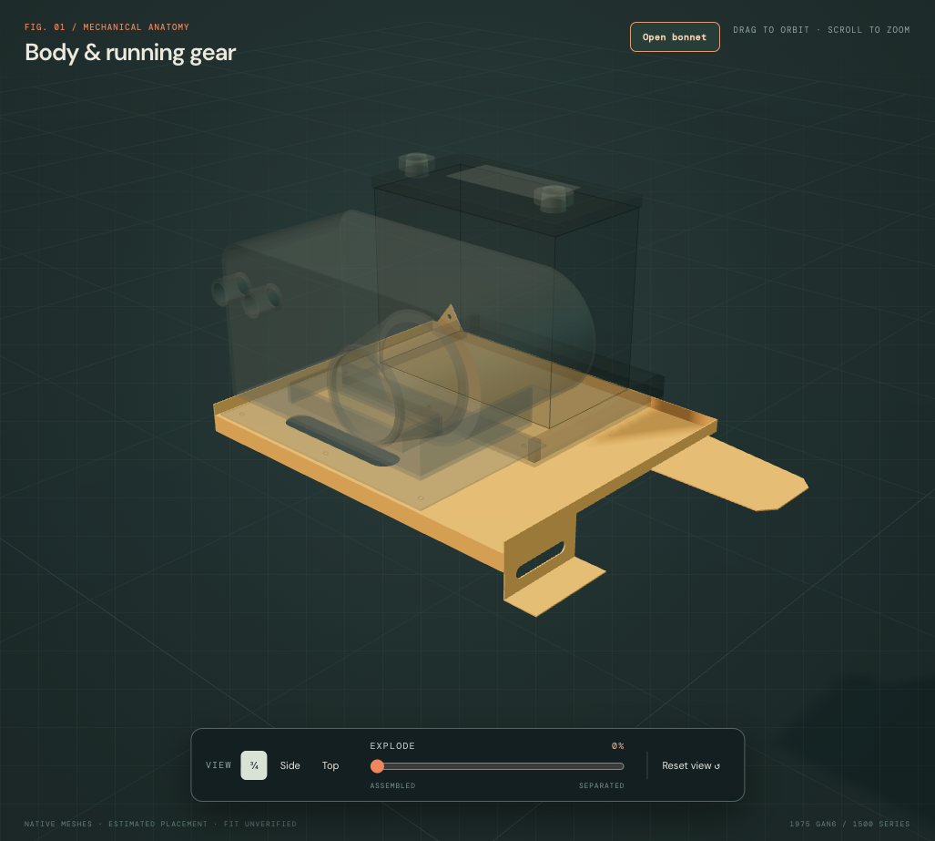
The existing platform mesh, sheet contour, oblong feature and pose stay unchanged. A single tapered wing is placed provisionally toward positive X; a downstanding web/foot follows that side’s forward edge, and a triangular bored ear meets the opposite rear return. No mirrored second wing is inferred. This orientation is a construction choice, with no owner-fitted handedness established.
| New reference role | Declared construction | Evidence limit |
|---|---|---|
| Lateral wing | 125 mm extension with tapered plan outline | Shared illustration only; actual side, extent and body attachment unknown. |
| Downstanding leg and foot | 45 mm drop, 35 mm foot, 65 × 12 mm slot interpretation | No verified pressing, slot size, fastening or receiver location. |
| Raised rear ear | Tip 40 mm above the old platform plane; 3 mm bore radius | Estimated profile and hole role; no counterpart or fastener is created. |
All sections use the inherited estimated 1.2 mm gauge. Their shared reference faces fuse to one closed solid without positive material overlap. That checks construction continuity; it does not establish a seam/weld map, continuous load path into the car or mounting strength. The features stay fixed in the general separation view because they represent welded support roles. Selecting an individual section is an inspection subdivision, not a removal instruction.
The heater, cabin-air, body, pedal, wheelhouse, steering and electrical source geometry remains held. Browser checks also retain the battery, tray and clamp world bounds. No positive contact was found between the new features and the selected native neighbors; this does not cover all coarse battery/tray surfaces or verify fitted clearance. The heater-base/body aperture, battery tray, body receivers and loaded support remain unregistered. No repair/drilling template, support rating, safe release or verified replacement path is supplied.
Keep the comparisons distinct
The factory battery plate, PDF p. 186 ↗ shows tray, bar, packing and hooked-rod architecture. Its printed applicability lists earlier HAN/GAN sequences rather than a fitted GAN6 survey. The 1500 battery-fittings listing ↗ corroborates a clamp-bar and hooked-rod arrangement. Neither source proves those parts are installed with this replacement battery.
The revised heater casing
The maintained CAD now replaces its shallow box with a broad, taller casing and rounded blower-side region, a hollow forward air neck and two open water ports near the upper front edge. IMG_6890–6892 and the factory 1500 heater plate, PDF p. 280 ↗ support those relationships. The revised 330 × 160 × 148 mm envelope, wall thickness, port and neck sizes remain estimates.
The factory lists a separate motor/mounting plate and matrix for the 1500 assembly. Those hidden internals are not reconstructed. Its part numbers do not identify this fitted Smiths unit, and the North American and California hose/control branches must remain distinct. The two modeled water ports and round air opening are open boundaries; no complete circuit or verified airflow direction is assigned.
The original main casing rear plane and lower datum are retained, with the added lower base extending beneath it, so the engine and nearby battery/support references are not moved to manufacture fit. The revised envelope can expose different model gaps or intersections. None is a measured car clearance, safe support point or validated heater-removal route. Older comparison/imported builds retain their own shallow heater geometry and are labeled accordingly in the engine inspector.
The heater assembly study ↗ now separates casing, rear cover, estimated core/seal and blower, with local hose/tap relationships and explicit untraced boundaries. The original casing dimensions are preserved.
Whole-car heater layout estimate
The whole-car layout now places the complete heater and local controls 80 mm rearward of the inherited engine-relative drawing. IMG_6891/6892 show it closely ahead of the battery; the rounded shift is a layout estimate, not a measured position. The model-plane gap falls from about 94 to 14 mm, which does not establish actual clearance. The original upper case envelope and orientation remain; the lower base/seal reconstruction uses the same pose. The battery, shelf, bulkhead and engine stay in their independent reference frames. Heater B is now 80 mm from the old return-pipe comparison endpoint; no joining hose or body mounting is invented. Dedicated engine CAD and the separate source STEP retain their original source pose.
What this rehearsal supports
Use the model to distinguish the battery, terminal regions, heater, ledge and catalog retention before comparing them with the supplied photographs. Selecting the battery or clamp and using the general separation slider exposes their reference shapes. The ledge, tray and short cable segments remain fixed for inspection.
The model does not simulate cable disconnection or flexing, retention release, a battery lifting path or verified bonnet/heater clearance. It supplies no replacement or electrical isolation procedure. Use the applicable complete workshop instructions for actual work.
The new electrical surroundings study ↗ uses IMG_6901 to extend the yellow-covered battery lead to its observed body-bolt relationship. Its geometry remains estimated; polarity and a sound electrical bond are unverified. The red cable’s remote destination remains open.
Remaining evidence boundaries
The supplied views establish the visible case and surroundings. The readable MAXX-51R designation supports the catalog comparison, but the views do not establish measured case dimensions, production-specific construction, terminal polarity, other hidden cable destinations, lower tray and anchors, installed hold-down, loaded support, or tool and lifting access. Those gaps are recorded separately from the visible evidence; no additional capture is needed to inspect this reference model.