At the fusebox
and body connections.
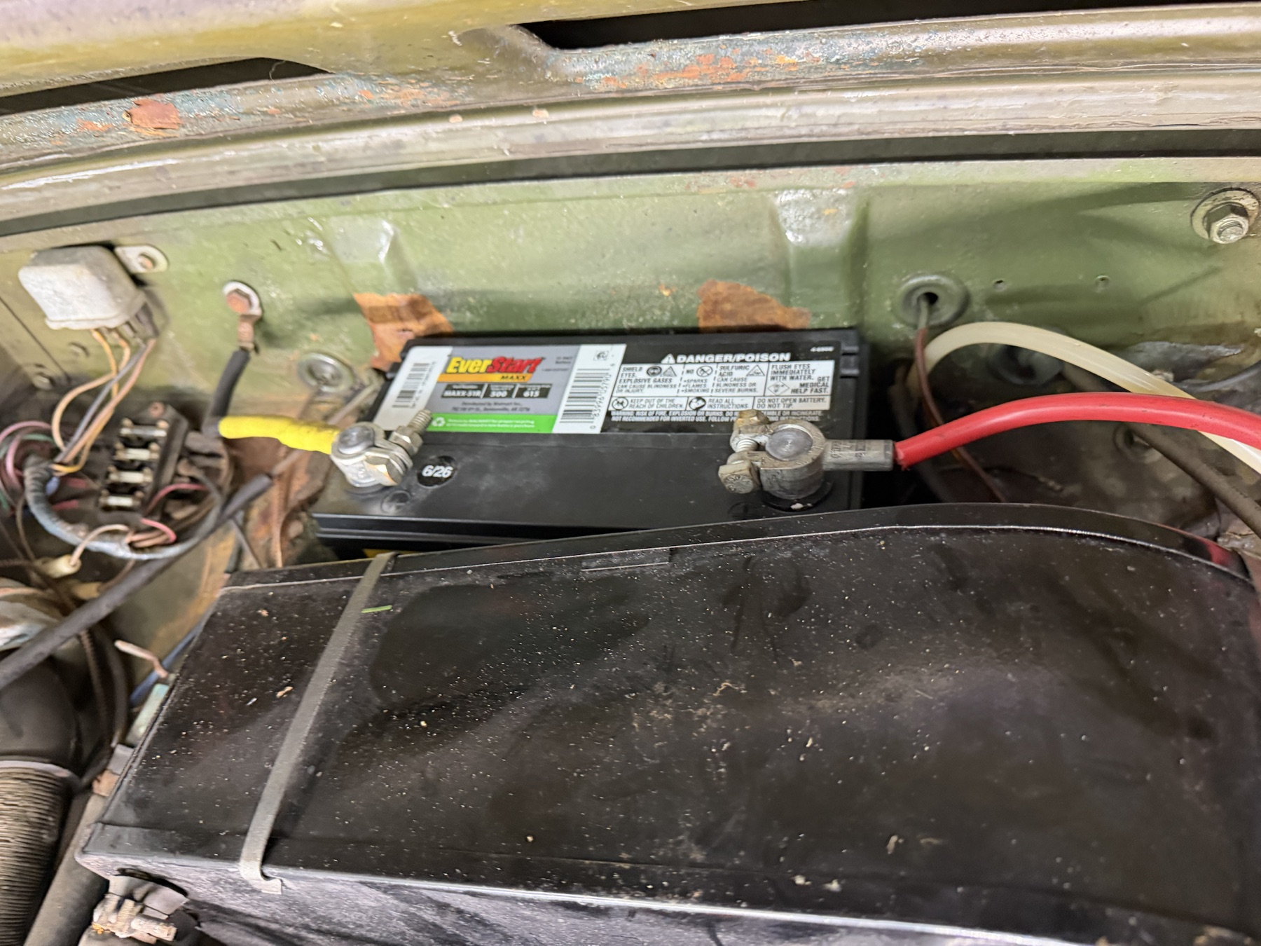
The model now distinguishes the exposed four-fuse box, nearby unidentified metal cans, local wire tails and loom loop. The existing yellow-covered battery lead continues to a body-bolt reference; the red cable remains untraced. A separate slender line/grommet crossing retains its unknown identity.
Inspect the local obstacle chain
Four glass-fuse envelopes sit between estimated contact cues. The contact shapes are recognition geometry; they do not specify internal buses or terminal pairs. Wire tails and the loom loop end openly before untraced joins. Neutral drawing colors do not encode circuit roles, conductor sizes, tracer colors or actual terminal assignments.
The upper metal can and lower cylindrical device have no assigned relay, flasher, regulator or solenoid identity. Their visible context is retained without turning catalog similarities into a fitted identification. The separate line through the bulkhead grommet is not identified as an electrical conductor, hose or capillary. Its body opening and all registration coordinates are estimates.
The battery lead has stronger evidence now
IMG_6901 allows the yellow-covered lead to be visually followed from its terminal clamp into a black segment and a body-bolt lug. That updates the earlier fully-untraced destination note for this lead only. The model joins the existing local cable cue to the estimated lug neck. It does not establish battery polarity, a sound electrical bond, conductor specification, the red-cable destination or a valid starter/charging circuit.
Factory comparisons stay separate
Factory PDF p. 188 separates North American main-harness variants by chassis, including changes at GAN6-159054 and GAN6-166304. The non-North-American harness on p. 187 is a separate branch. PDF p. 191 distinguishes battery and engine/body earth-cable architecture, clips and grommets. None supplies fitted route coordinates.
PDF p. 192 and the MGOC four-fuse 37H4727 comparison support the holder architecture. Catalog ratings and relay applications are not applied to the fitted fuses or unidentified cans. The current model assigns no fuse duties, ratings, harness part number or relay pinout. The coil’s “WITHOUT EXTERNAL RESISTOR” marking also does not establish the car’s actual ballast wiring.
All new sizes, positions, wire sections, tail counts, mounting patterns, grommet/hole and connector shapes are estimates. No continuity, electrical compatibility, load protection, contact quality or complete circuit is verified. Moving the fuse group exposes the reference; it is not a verified release direction, safe disconnection sequence or replacement procedure. Keep actual terminal/route evidence separate from catalog circuit diagrams.
Native reference files
The builder checks positive valid shapes and STEP round-trip. Browser checks cover metric placement, selection and the estimated bulkhead crossing. These construction checks do not prove a fitted electrical connection or clearance. The core engine and prior native exports are unchanged.