Record the starter connections as found.
Use this sheet while photographing the fitted starter and its solenoid. Add one row per visible cable, wire, or terminal. It keeps observations separate from circuit assumptions and gives you a record for reassembly.
Secure the car and isolate the battery according to the correct workshop procedure. Photograph the whole assembly and each terminal before loosening anything. Do not infer a terminal's function from its position in the provisional CAD or from a Spitfire diagram.
Start with the owner photos
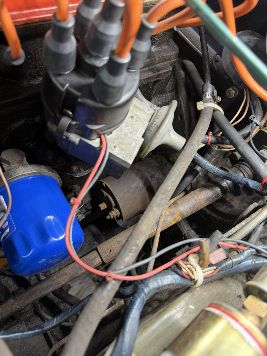
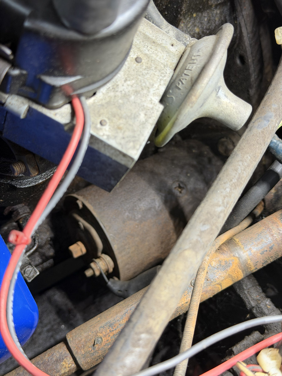
These views do not establish every cable end, terminal marking, or route. New square-on photos of the starter rear and remote solenoid are the useful next evidence.
Connection record
This browser stores the text locally. Export a copy to keep it with the photos; photos themselves are not stored or exported. Leave an unknown destination blank.
Connection
Check the right manual
The British Leyland AKM4071/B contents, PDF page 8 lists starter removal/refit as 86.60.01, solenoid removal/refit as 86.60.08, and the 1975 U.S.A. wiring diagram as 86.00.03. These are pointers to the procedures and circuit; their pages have not been inspected here. The original publication catalog also lists 1975 North American Midget manual AKM3267. Compare either diagram to the fitted harness before assigning circuit roles.