Identify the starter before planning its removal.
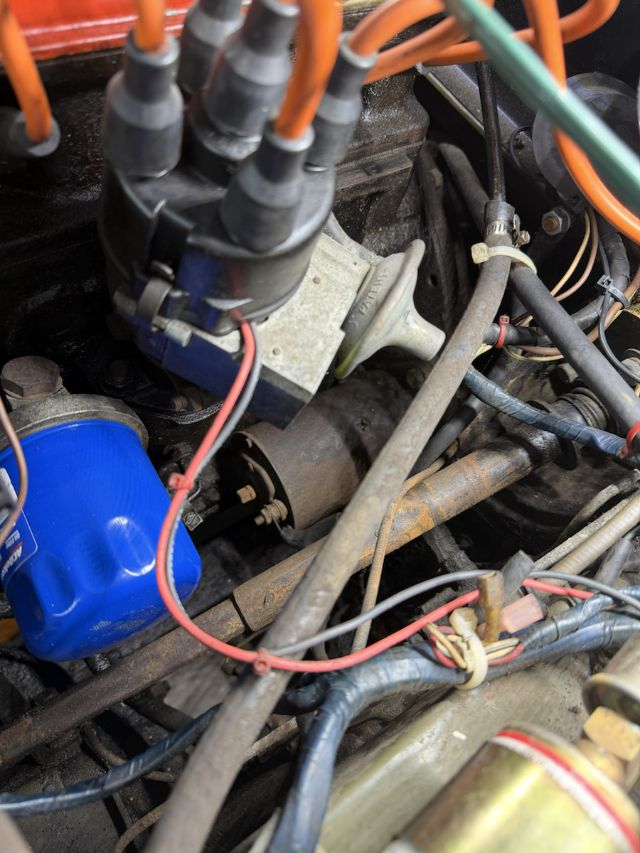
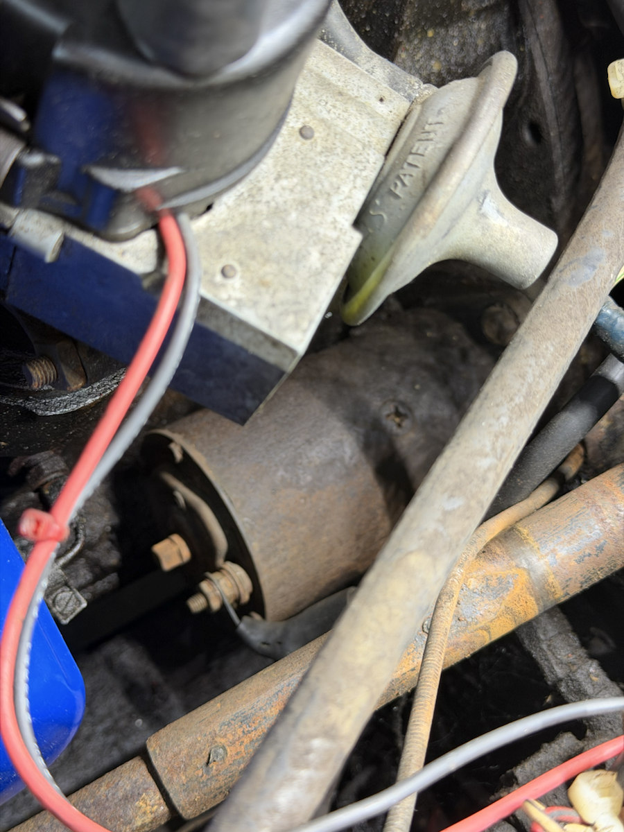
The original Midget 1500 parts book specifies a Lucas M35J. IMG_6966 and IMG_6969–6970 show the starter on this car below the distributor, beside the blue oil filter, but no maker or type marking is readable. The 3D assembly now sits on that photographed side of the engine. Its exact mounting station and removal path still need direct measurements.
What the car shows
Inspect the pinned owner photo ↗ IMG_6970 shows the cylindrical starter beneath the distributor and beside the PF53 oil filter. The rear bracket, fasteners and at least one cable connection are visible; the drive end, mounting bolt heads, model marking and full cable route are hidden. IMG_6969 gives a closer angle and IMG_6966 shows its relation to the filter. The shared-side placement is photo-supported; the CAD center, body length, terminal shape and clearances remain provisional.
What the sources establish
| Original starter | The factory Midget 1500 electrical parts list names starter assembly 13H5798 as Lucas M35J. This identifies the catalog specification, not the unit currently installed. |
|---|---|
| Pinion and bolts | The same list identifies barrel and pinion 67H5010 and two BH606071 starter mounting bolts. A Midget 1500 supplier listing describes the 67H5010 pinion as nine-tooth; it also lists another ten-tooth option. Count the fitted teeth before choosing parts. |
| Motor diameter | A Lucas starter training drawing describes the M35J as an inertia-drive starter with a 3½-inch (88.9 mm) yoke outside diameter. This is the original M35J yoke reference, not a measurement of this car. |
| Compatible replacement interface | HC-Cargo 111103 supplier specifications list 125.45 mm between the two mounting holes, 173.55 mm behind the mounting face, 138 mm in front, and 321.5 mm overall length for a replacement sold for Midget 1.5 and Lucas 25149. A HC-Cargo catalog independently lists the 321.5 mm length. The CAD uses the replacement hole spacing as an interface reference and its front/rear proportions to shorten the provisional motor shell and extend the drive. The supplier’s front-plus-rear figures do not add exactly to its overall length, so these are guiding envelopes, not exact endpoints on the Lucas or fitted starter. Its pictured ribbed rear casting differs from the dark, mostly smooth end visible on this car; the CAD rear exterior follows the owner photos. |
What the Lucas workshop drawing adds
The Lucas M35J workshop instructions, PDF p. 87 show an exploded windowless yoke with four pole shoes, a separate armature, a face-type commutator molded onto that armature, and two independently fixed end brackets. The drawing supports the parts and their order, not the wall thickness, radial clearance, screw coordinates or motor length used in this CAD. It prints the 3½-inch yoke diameter as 90 mm; the other Lucas training sheet converts that diameter to 88.9 mm. The public CAD retains the exact inch conversion until this car is measured.
Read the virtual assembly
Click eleven study parts separately: hollow steel yoke, four pole shoes, armature and shaft, face commutator, drive-end flange, two mounting bolts, smooth commutator-end bracket, terminal stud, drive shaft and spring envelope, and nine-tooth pinion. The yoke diameter is scaled to the Lucas drawing. Mounting-hole spacing follows the 125.45 mm compatible-replacement listing. Body length, casting contours, mounting-hole clocking, spring, terminal and tooth shapes remain estimates. The starter sits at a provisional intake-side station near the flywheel in the engine study. Owner photos establish the installed side and neighboring parts, but no measured bolt coordinates fix its real station. If the fitted motor is positively identified as an M35J, the CAD inspector can save direct yoke diameter, axial body length and mounting-hole center spacing and use them to build a separate owner STEP. Spacing moves the two flange ears and bolt cues along their provisional axis; it cannot establish flange clocking, installed coordinates or the removal path.
The pinion is shown at rest clear of the ring gear. Its axial travel and gear mesh are deliberately absent because those dimensions have not been established; do not use the apparent gap to judge a replacement starter or flywheel.
Before deciding the starter needs replacement
The Lucas M35J troubleshooting page distinguishes a starter that spins without cranking the engine from one that does not operate or cranks slowly. Record exactly which symptom occurs. For a slow or silent starter, its first checks are battery condition, terminal cleanliness and tightness, heavy cable and engine/gearbox ground connections, then the switch or solenoid circuit. Those checks may reveal a fault outside the motor. Verify the fitted wiring and use the proper electrical test procedure before disconnecting or probing connections; this site does not identify the current starter or provide a live-circuit test.
Capture this car's starter
- With the car secure and engine unable to start, photograph the starter, drive-end flange and rear connections from accessible sides. Include a ruler in the same plane as the motor case.
- Read the maker, model and stamped part number on the fitted unit. Compare its case and drive style with the M35J reference; record any replacement or reduction-gear type rather than assuming it is original.
- Before disconnecting electrical connections, isolate the battery according to the applicable workshop procedure. Photograph and label every cable, stud, nut and insulating part.
- Record both mounting bolt heads and access directions, the center-to-center spacing of the two flange holes, case diameter and length, and the straight withdrawal space around the body and bellhousing. If the unit is removed during real service, photograph the nose and count pinion teeth.
- Enter the observations and photo filenames in the project evidence log. Check the identified starter's service procedure and replacement fit before using the virtual exploded view for a work sequence.