A compact support.
Keep its limits visible.
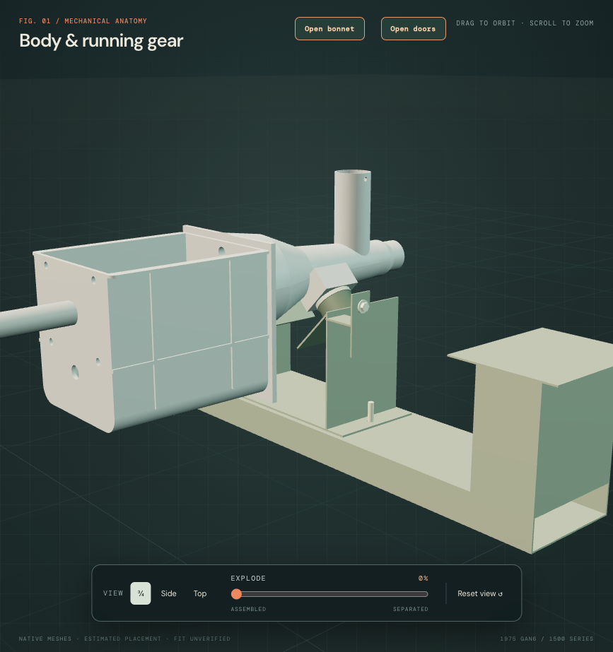
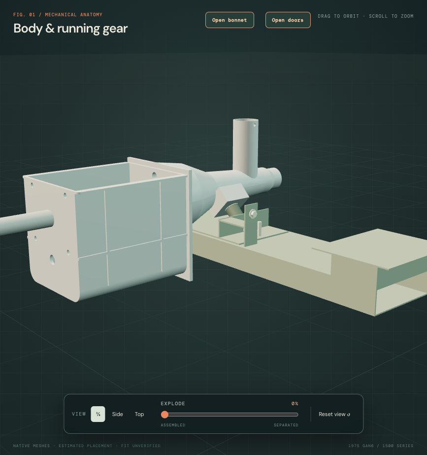
The former rear gearbox cradle and body beam hung far below the floor reference. Smaller supplier-dimensioned mount comparisons, a raised beam and shorter cradle webs now replace that deep construction. The gearbox casting, its mounting-pad bearing planes and the body fixing axis lines stay.
A folded channel beneath the mount pair
The factory mounting illustration shows an upturned cradle edge and elongated openings in the inclined mounting faces. The current native cradle now uses rounded channel folds and centered slots in place of its flat base edges and circular openings. The gearbox, rubber pair, thirteen other support groups and all source placements stay.
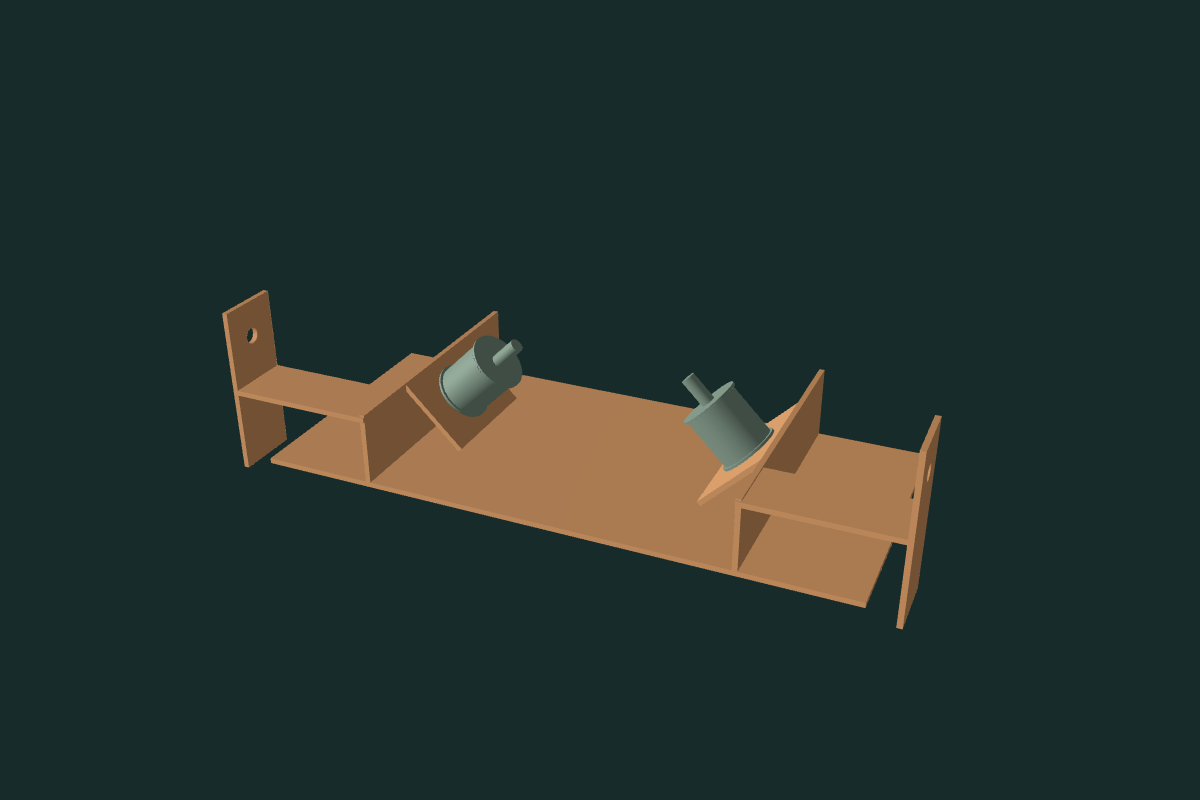
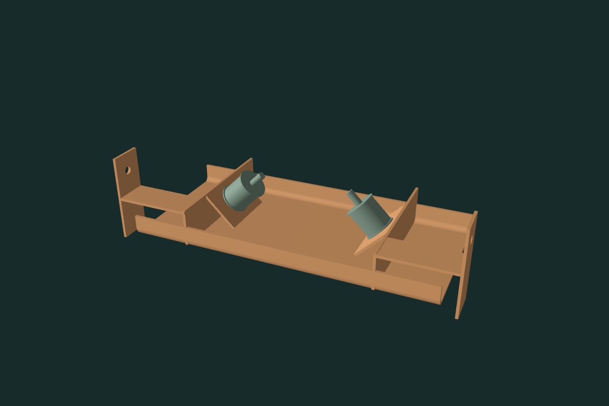
The selected 24 mm lip height, 6 mm inside bend radius, 3 mm gauge and 9 × 18 mm slots are construction estimates. The second repeated channel edge is an interpretation of the exploded drawing, not a surveyed CHA266 pressing. Original outline bounds, central floor, fixing centers, gearbox pad faces and body/tunnel axis lines stay. Slot centers stay on the previous round-hole axes; this does not establish a fitted adjustment range or a drilling map.
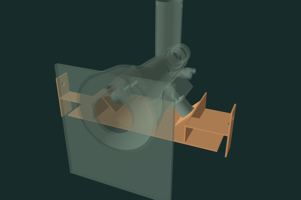
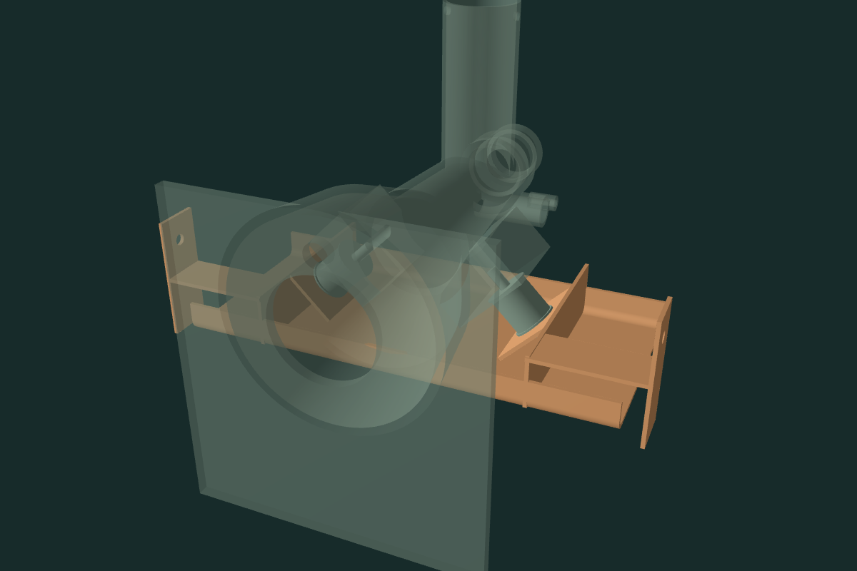
The new channel edge overlaps the retained gearbox extension by 161.296072 mm³. Earlier cradle/tunnel, floor and crossmember source contacts remain. These are drawing conflicts, not diagnoses of interference on the actual car. Neither the gearbox nor surrounding body is moved or cut to conceal them. Fitted common alignment, loaded rubber, hidden joints and a replacement path remain unverified.
Earlier compact-support reconstruction
What the evidence establishes
The factory mounting plate separates CHA266, two rear rubbers and base/side fixing roles. It distinguishes122689 from CHA615 at GAN6-176236 and calls for CHA615 in pairs. Neither branch is identified as fitted. North American restraint, cable and tie-bar roles remain unselected.
A supplier’s annotated122689/CHA615 photograph gives a34mm maximum body diameter,34mm length between the outer metal faces and17mm exposed studs. Those are catalog comparisons. Its combined label does not resolve the factory change point or identify the car’s actual mounts. The earlier reference used60.96mm metal-face diameter and49.1067mm outer-face spacing.

British Motor Heritage lists2A5478 as the full-width centre-crossmember assembly for1958–79. That establishes a body-panel role, not the dimensions or attachment of a removable gearbox member. Unscaled donor gearbox views support paired inclined mounts at extension pads. Existing owner IMG_6919 and IMG_6341 provide underbody/cabin context without surveying this hidden rear support.
What changed in the construction
The mount centres move along their existing45-degree axes to keep the inner gearbox-pad bearing planes fixed. Maximum diameter and outer-face spacing follow the34mm comparison. The1.5mm face gauges,31mm rubber waist/body and unloaded cylindrical profile remain estimates; the supplier does not specify that internal split.
A rounded246mm cradle-base bearing plane replaces110.0667mm in the construction frame. The beam bottom changes from59.2667 to195.2mm. Beam width, depth, section height and floor-end upper planes stay. The shortened end channels and48×68mm cradle plates are construction hypotheses guided by compact mounting architecture, not fitted sections, welds, dimensions or a verified load path. The broad base outline, tunnel-side holes and long-bolt axis lines stay. The retained base-axis Y coordinate is an arbitrary point on a vertical line, not the new bearing-plane station.
The estimated inclined bores continue through crossing webs. Separate smooth studs and88.9mm long-bolt comparisons retain explicit limits: no verified thread, engagement, torque, bond or compression. The raised long bolts follow the revised beam underside without changing their length. No exhaust, cabin, engine or gearbox mesh is trimmed or moved to manufacture clearance.
Inspect the support chain
Unresolved source contacts
The limited static sample retains the following positive intersections. These are reconstruction discrepancies or source divisions, not actual-car interference findings. The former support/exhaust intersections disappear in this source sample after the compact rebuild; that does not verify a running or service clearance.
| Source comparison | Contact mm³ |
|---|---|
| rear power connected folded cradle inclined faces and tunnel ears / cabin hollow tapered tunnel with declared lever mouth reference | 1689.0322 |
| rear power connected folded cradle inclined faces and tunnel ears / cabin left floor with retained seat bores reference | 7.8287 |
| rear power connected folded cradle inclined faces and tunnel ears / cabin right floor with retained seat bores reference | 7.8287 |
| rear power two tunnel side washer envelopes / cabin hollow tapered tunnel with declared lever mouth reference | 6.5549 |
Workshop boundary
Use the model to identify the extension pads, rubber pair, cradle, long bolts, tunnel-side fixings and body beam. Inspection separation remains illustrative. The fixed cradle and beam during display separation do not establish removal ownership, release order, a support point or a withdrawal direction.
The UK front-mount operations12.45.01/.03 do not establish the applicable North American rear-support procedure. Fitted mount/restraint identity, loaded geometry, actual ground clearance, safe support/lift, tightening and verified replacement/removal paths remain unresolved.
Native checks
Fourteen groups contain26 valid positive solids, including one connected cradle. Mesh/native volume agreement, the34mm envelope,17mm exposed studs, retained gearbox bearing planes/fixing axes and unchanged transmission/cabin mesh payloads are checked. These establish source construction, not fitted support.