Connect the lever
through the tunnel.
A single selector rail and yoke, lower lever seat, separate lever and knob, slotted retainer and pins now connect the rear extension to the cabin. A hollow outer gaiter, curved flange/retainer and shared tunnel-fixing references replace the solid boot envelope.
Use the 1500 arrangement
Factory p. 82 separates single selector shaft 22G2053, yoke 22G2291 and pin, lever seat 22G1424, rear extension and long/short retaining pins. P. 83 separates 22G2797 lever, 22G1434 retainer, knob, change-speed seal, outer gaiter and AHA9487 retainer with three screws plus one different screw. These establish parts and connection roles, not this model’s contours, neutral pose or hole map. A separate earlier A-Series remote housing is not added to the 1500.
The early North American seat-belt inhibitor branch and Canada-only selector-shaft gaiter/clips remain unselected. The reverse-lift plate, lever plunger/spring and actual change-speed seal are not reconstructed. Their absence is not a claim that this car lacks them. The annular shaft-seal reference has no loaded sealing behavior.
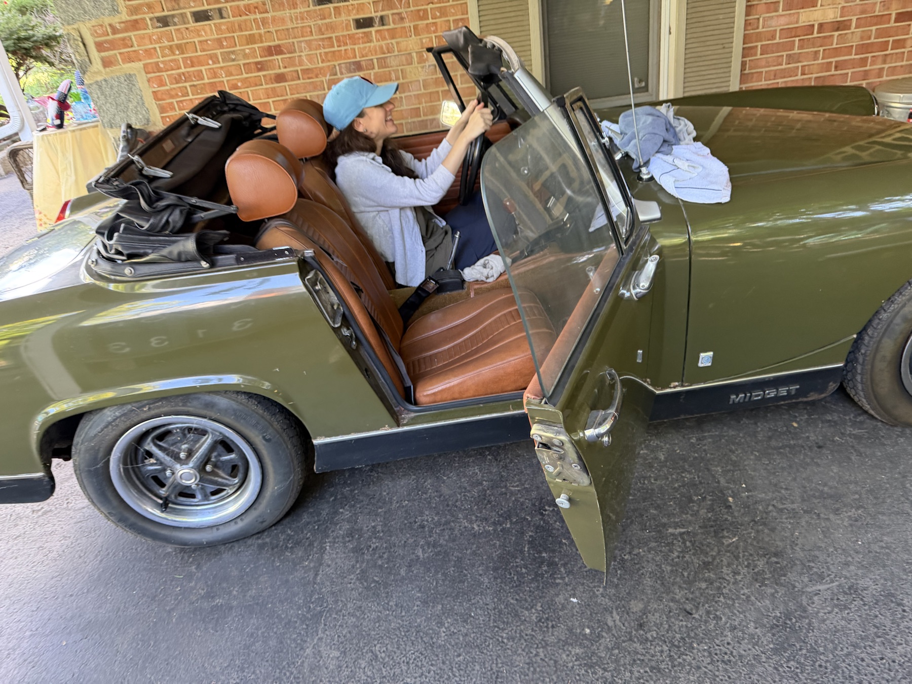
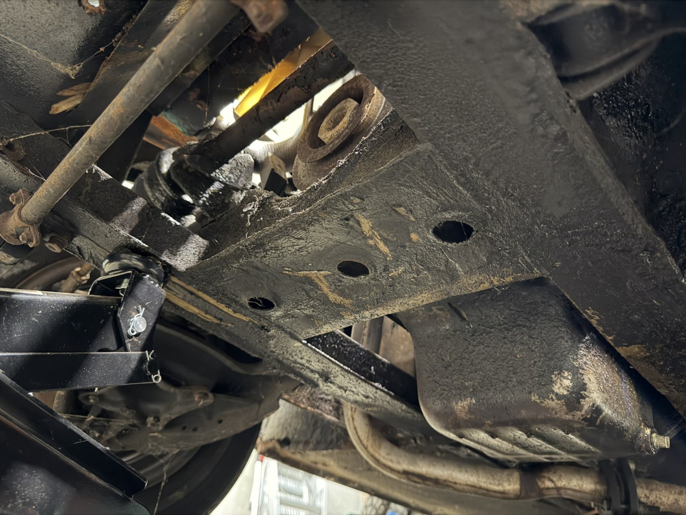
Owner IMG_6341 supplies cabin context with controls partly obscured; IMG_6919 supplies underside context. Neither identifies hidden fitted selector hardware or calibrates the gearbox/tunnel interface. No direct owner dimensions are applied and no repeat capture is requested.
Retained datums and declared changes
| Assembly | Construction and limit |
|---|---|
| Lever / knob | Prior fulcrum-ball and knob centers are retained. Separate lower finger, spherical seat and blank knob/socket expose interfaces without identifying the actual lever, knob, thread, preload or reverse-lift mechanism. |
| Rail / yoke / case | A smooth rail, open-cup yoke and transverse pin share construction axes. Main case and extension gain a matching estimated passage and separate annular seal. No forks, detents, interlocks or operating gear-selection model is present. |
| Extension / cap | The old 55.0333 mm-radius turret envelope becomes an estimated 30 mm outer / 27 mm inner-radius hollow neck. Old base/top stations are retained. Open-bottom cap slots and two smooth pin envelopes expose retaining roles; they do not verify a bayonet lock, actual casting or release direction. |
| Body gaiter | The old tunnel-mouth oval is retained. A hollow oval cuff is trimmed to the current tunnel envelope and tapers to an open mouth on the retained sloping stem at body Y=.76. The mouth shifts from former Z=-.32 to about -.32941 body units; this is a construction correction, not a surveyed boot pose. |
| Flange / retainer / fixings | Curved thin references follow the existing tunnel construction. Four estimated fixing axes follow its local normals and share passages through flange, retainer and sheet. Three-plus-one screw grouping follows factory count only. Hole coordinates, axis angles, length assignment and head bearing/seating are not verified. |
All new profiles, dimensions, pin maps, spherical/tapered interfaces, neutral positions, shell thicknesses and clearances remain estimates. The 0.3 mm construction offsets do not represent fitted clearance or compressed rubber. Source-solid consistency does not establish gear engagement, reverse-lift travel, detent force, actual retention, thread engagement or safe access.
Inspect both sides of the body opening
Use selection and isolation to follow lever, seat, retainer, pins, yoke and rail boundaries, then inspect the outer gaiter’s separate flange/retainer and the curved tunnel. The body gaiter and retainer stay fixed during the display separation; other parts translate illustratively. That convention does not establish which parts stay with the body during a real job.
The parts drawing is not a workshop procedure. No applicable later service sequence, safe support arrangement, tightening figure, spring-release method, installed pull/rotation clearance or verified withdrawal path is established here. The earlier A-Series remote-housing procedure must not be applied by analogy. A body mouth that admits the lever in this reference does not prove a fitted replacement or gearbox extraction opening.
Native exports
The new asset has thirteen source meshes in twelve groups and seventeen valid STEP solids. Build it using the current cabin section metadata, then rebuild transmission and cabin-understructure so they read the shared passage/fixing map. Only case/extension meshes change in the retained transmission export; six other meshes are identical. Only the tunnel changes in cabin-understructure; its six other meshes are identical. Superseded solid selector/boot meshes are removed.
Validation covers solid validity/STEP round-trip, rail/yoke and lever/seat/cap/knob consistency, sampled assembled contacts, shared passages with neighboring material, separate pin/screw occupancy, metric placement/picking, inspection ownership and study/export links. It does not certify fitted clearances or service readiness.