Current revision: output-to-speedometer connection ↓
Through the
gearbox.
The solid gearbox block is replaced by a native hollow case, separate cover and rear extension. The input guide, input shaft, gear lever, output flange and two propeller-shaft joint references explain the connection from clutch housing to differential.
Case dimensions, hole patterns and installed stations remain estimates. Unscaled supplier photographs now correct the broad case/tail proportions; separately attributed catalog bearing envelopes are distinguished below. Millimeter units preserve scale consistently; they do not make these shapes measured reproductions. Owner photographs and the existing evidence remain available, but no fitted gearbox survey is asserted here.
Oil-service boundaries and tunnel access gap
The main case now has an estimated right-side filler and downward drain,each with an open passage,local boss and separately selectable square-headed plug. Factory PDF82/107-C20 lists114774 filler/drain plugs,quantity two. The donor's opposite-slave-side view supports the right-side filler role;the adjacent slave-side view shows the lower drain context. These are donor comparisons,not identification of this car's gearbox.

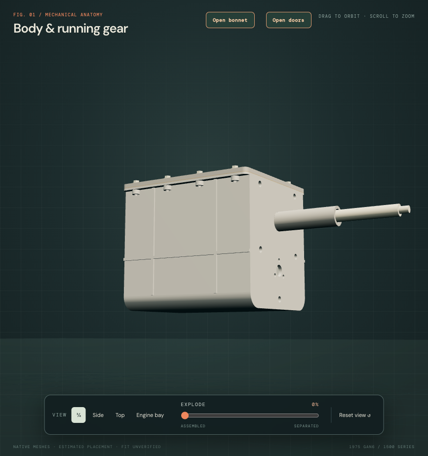
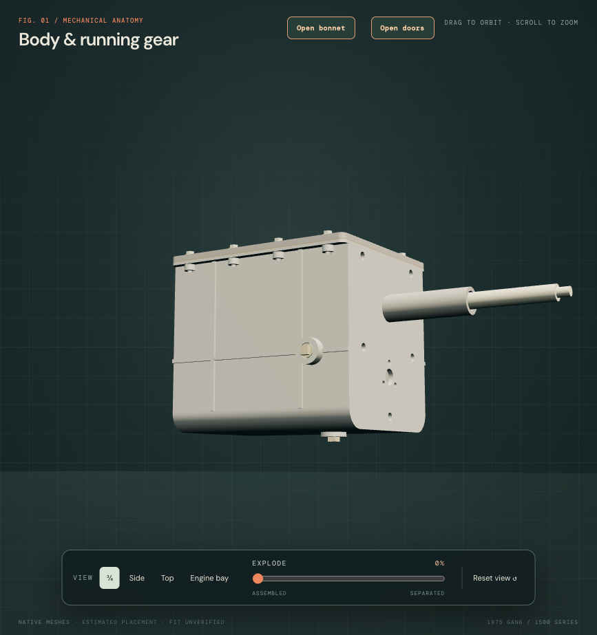
The filler face is estimated at native[-112,-60,front−50]mm,and the drain at[0,bottom−6,front−80]mm. The9mm passage radius,16mm boss radius,8.5mm smooth plug radius,10mm shank and11mm square head are estimates. Threads,taper engagement,sealing,oil level/capacity,torque and tool clearances are not established.
The current filler axis is26.133mm below the retained cabin floor plane. This is a comparison between estimated drawing frames,not a measurement of your car. No tunnel opening is cut or shifted around it. Supplier4G4920 identifies a rectangular access-plug role,but does not locate its fitted opening on this1975 car;earlier Midget handbook access instructions are not transferred to the1500 arrangement.
Accessible workshopTeil1 PDF29/printed29 is explicitly UK-specification maintenance artwork;it supports service-role context only. It is not used as verified1975 North American servicing instructions. No removal/replacement path or actual cabin access is verified.
The case-to-cover joint
The plain lid now has an estimated shallow pressing, nine fixing passages and separate smooth screw/washer references. A single unloaded gasket layer sits within the former cover's lower0.8mm, preserving its top plane and outer outline. Local case boss envelopes carry the shared bores; the internal shafts, controls, bellhousing and output stations stay.
Factory PDF82/107-C20 lists22G1884 cover,nineSH604041 screws,nineWL600041 washers and22G1911 gasket quantity two. The second gasket's allocation remains unresolved;two stacked top layers are not inferred. Workshop37.00.01/printed138 and its139 key show the separate cover/gasket/bolt architecture. These are exploded references;full gearbox removal/overhaul pages remain unread.
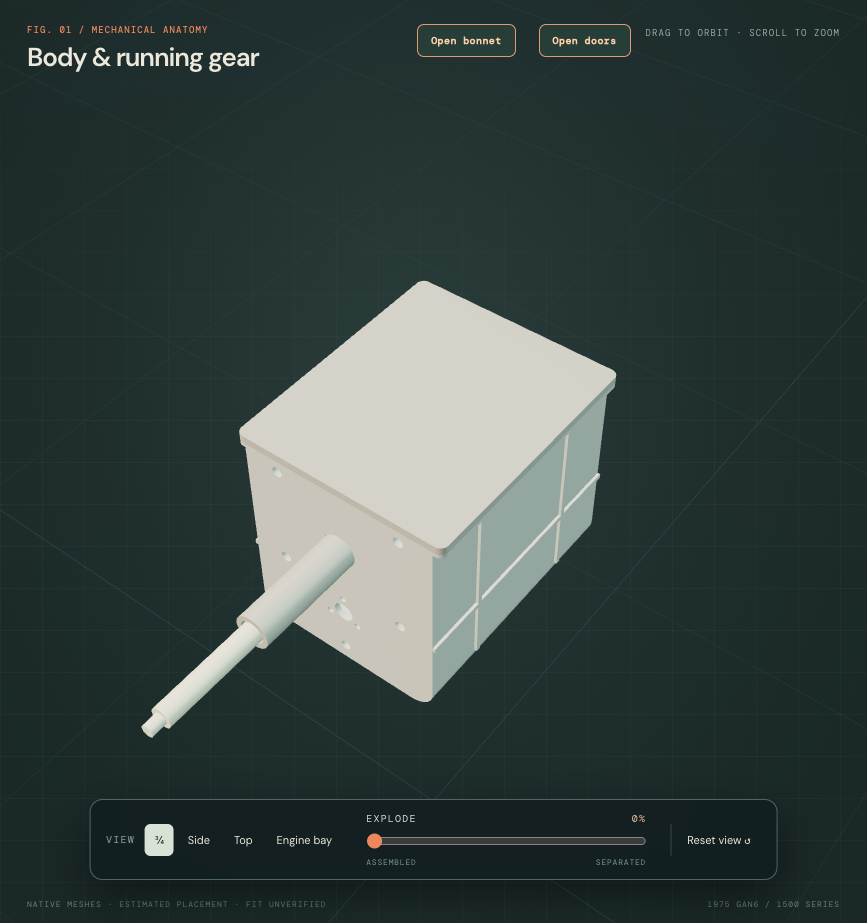
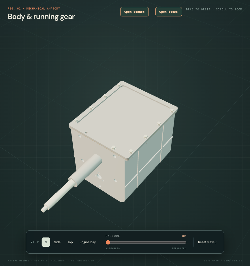
All hole coordinates,3.5mm plain bore radius,7mm boss radius,12mm boss depth,4mm dish depth,0.8mm gasket and smooth hardware sizes are construction estimates. The gasket is unloaded and washers represent the factory lock-washer roles without verified split or preload. No threads,engagement,torque,sealing,loaded compression or actual-car access/removal path is established.
Inspect the connections
Connect the mainshaft to the output flange
The long tail formerly contained only a plain shaft and hollow output flange. It now contains separate rear-bearing, seal, front-washer, smooth speedometer-wheel and flange-retention references. A stepped shaft tail, bearing/seal pockets and estimated housing shoulders connect those roles under the retained case and output planes. The narrow tail end remains clear of the existing propshaft bolt-head references; the larger bearing housing begins farther forward. Body, engine, clutch, propshaft and rear-mount poses stay fixed.
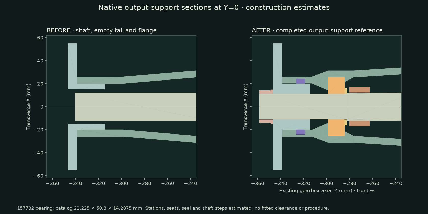
Factory plate81 lists 157732 rear bearing, 22G2353 extension seal, 155756 washer, 22G1752 six-tooth speedometer wheel, 155755 flange, WA116101 washer and 510618 nut. Rimmer supplies the bearing envelope: 7/8 inch bore, 2 inch outside diameter and 9/16 inch width (22.225 × 50.8 × 14.2875 mm). Those are catalog dimensions, not identification or measurement of the fitted bearing.
All axial positions, shaft steps, 26/31.4 mm outer tail radii, pockets, shoulders, radial drawing allowances, seal section and hardware profiles are estimates. The six-tooth role is deliberately smooth: no tooth mesh, driven pinion or cable connection is established. Nominal shaft/bearing contact does not establish a loaded fit; flange engagement has no modeled spline, thread or torque. Existing body/engine registration and clutch release gaps remain unresolved.
Housing omission and separation expose the relationships for inspection. They are not an extension-removal sequence or a verified seal/bearing replacement route. Propshaft release, flange retention, support, tunnel/tool access and applicable workshop procedures must be established before rehearsal can be trusted. No actual support strength, endfloat, seal compression, working speedometer or replacement feasibility is claimed.
The previously empty internal layout
Factory plates 80–82 distinguish the first-motion gear/shaft, mainshaft gears, two synchronizer assemblies, laygear and layshaft, reverse idler/spindle and two selector forks. Smooth estimated envelopes now represent those internal roles. The short case and long extension now replace the reversed proportions of the previous scaffold. Internal axial stations follow the new case partition; the exterior input shaft, output and lever/control axes retain their estimated stations.
Factory plate 82 distinguishes the 22G1408 fork shaft from the 22G2053 selector-control shaft. A separate support-shaft comparison and offset fork collars now replace the earlier incorrect direct attachment to the control rail. The support axis at X=55/Y=50.8 mm is a layout estimate; the operating connection, interlock and case retention remain unresolved.
The 104433 catalog bearing listing supplies 24.4 mm bore, 63.5 mm outside diameter and 19.1 mm width for the input and center bearing roles. Those are supplier comparison dimensions, not fitted measurements; the published bore is preserved as written. Shaft journals, bearing stations and all gear/fork geometry remain estimates.
The layout has no gear teeth/counts, helix, ratios, splines, synchronizer engagement, working interlock or loaded bearing fit. The former 25.0667 mm case/layshaft drawing mismatch is superseded by a shared estimated axis and shaft ends reaching the case planes. Front/rear layshaft passages and two bearing-support comparisons now show the relationship. Catalog bearing envelopes sit within estimated 31.95 mm-radius pockets and 42 mm-radius bosses, with 19.3 mm pocket depth and explicit drawing allowances. The revised case, cover and extension change their shape. Rear bearing, layshaft ends, gear/synchro/fork stations and selector seal follow the new shared construction layout; the front input gear, mainshaft/pilot and front bearing stay fixed. These are reference construction dimensions, not verified fitted bores, loaded seats, bearing retention or machining instructions. The internal-only study hides case/cover/body obstacles, while the case comparison shows the supports with the cover/body omitted for inspection, not because those parts can be removed in that order. General separation is illustrative and does not establish a disassembly, adjustment or replacement procedure.
Correcting the case and tail proportions
The RW Auto Classics 22G1553 listing photographs and Rimmer BHM5060R product photograph show a short main case and longer tapered rear extension. The earlier scaffold had those proportions reversed. Under the retained estimated input/output planes, the main-case/tail partition changes from 457.2/169.3333 mm to 260/366.5333 mm. This is an unscaled visual reconstruction, not a dimension extracted from perspective photographs or a factory drawing.
The donor listing does not identify the fitted casting on this car. Rimmer’s oil-seal-type unit is a comparison; the fitted scroll/rubber front-seal branch remains unselected. Existing owner IMG_6911/6915 shows underbody context without a calibrated gearbox envelope. The case/cover gains a narrower, lower ribbed main body; the rear case plane, center bearing, selector seal and internal axial spacing follow the revised layout. Input/output planes and lever/control axes remain the previous estimates.
Source-shape checks have been refreshed for the clutch, rear support and propshaft. The subsequent housing rear-web/gasket/four-fixing revision removes the earlier clutch-housing/boss/case overlaps in the reference shapes. The later open-fork/slave-entry revision removes housing/lever overlap; boot/rod overlap and engine/clutch frame disagreement remain, and the rear support now has paired extension-pad comparisons under revised estimated rubber axes; fitted mounting engagement remains unresolved. Neither a reduced overlap nor empty space proves actual-car fit, tool access or safe support.
What the factory plates establish
Factory parts plates 80–83 distinguish the main case, top cover, rear extension with selector turret, change lever and rear output flange. The lists include case 22G1553, cover 22G1884, change lever 22G2797 and output flange 155755. These are catalog identities, not identification of this car’s fitted castings.
Plate 145 distinguishes slip-joint and fixed-joint flange yokes, sleeve yoke and two GUJ101 journal references. It lists CHA336 from GAN6-154101. Actual shaft length, spline engagement and joint phase are unresolved. Early North American inhibitor-switch hardware is listed by chassis range; it is not assumed fitted or added to this study.
Drawing relationships and their limits
| Reference relationship | Basis and limits |
|---|---|
| Main case | Short ribbed body with rounded lower corners, open top and separate bearing/layshaft support comparisons. Estimated body 200 mm wide × 219 mm high × 260 mm long; top lip 220 mm wide and wall 6 mm. These are construction dimensions. Smooth internal roles are separately selectable; loaded fits and oil passages are unresolved. |
| Cover / extension | Separate selectable components expose the interior when isolated or hidden. The longer 366.5333 mm estimated extension has a tapered hollow shell and a hollow lever neck with shared selector/retainer-pin passages. The tail end uses estimated 26/20 mm outer/inner radii to leave the retained output hub and propeller-shaft fixing envelopes unobstructed in this drawing; these are not fitted clearances. Profiles, flange stations and cover thickness are estimated. Bolt counts do not establish surveyed hole positions; fixing hardware is omitted. |
| Output / propeller shaft | Estimated output and front joint flange faces coincide in this drawing. The four-hole 70 mm PCD is an estimate, not a machining or purchasing specification. The independent native propshaft study now supplies separate yokes, journals/caps/retainers, flange fixings and front sleeve/stub. The 70 mm pattern clocks45 degrees and front bores grow R4→R5.2; only the output mesh changes here. Old coarse joint meshes remain in this standalone export but are omitted from the combined viewer. A new estimated tube section and60 mm front cutback expose the slip boundary. Original output/differential stations remain unsurveyed. |
| Lever / gaiter / tunnel | The lever leans rearward above the extension. The single-rail controls study now supplies a separate rail/yoke/seat/lever/retainer and hollow outer gaiter with a curved flange, retainer and shared tunnel holes. All profiles, pose, maps, seals and installed clearances remain unverified. |
Input pilot reference
The external input keeps its old endpoint but now has an estimated 6 mm-radius,15 mm-long reduced tip, following the first-motion shaft role in factory plate80. It clears a separately sourced catalog pilot-bush comparison at the current engine export station. This does not identify the fitted shaft, establish running clearance or verify engagement. The clutch frame comparison records the remaining engine/bearing axial disagreement.
Use as a workshop study
Select the case and use Isolate to inspect its hollow construction. Select the cover, extension, lever, flange or either joint to follow that boundary into the whole-car surroundings. Existing clutch housing, release mechanism and rear support remain independent references.
General separation opens display groups. It is not a factory removal sequence, gearbox withdrawal trajectory, safe support arrangement, spline-disengagement distance or verified replacement procedure. Retaining the gaiter with the body is a display convention. Actual fastener access, tunnel aperture, exhaust and engine interference require a registered assembly and applicable workshop procedures before a removal rehearsal can be trusted.
Inspect the selector and body-gaiter chain. The earlier solid selector/boot source meshes are superseded; case/extension passages and neck are construction references, not fitted dimensions.
Complete the output-to-speedometer interface
The earlier output shaft had a smooth drive-wheel reference but no driven pinion or carrier. The tail now has an estimated hollow side boss and retaining-screw support, with separate smooth pinion/shaft, grooved hollow carrier, unloaded O-ring, split sleeve, oil-seal role and forked retaining plate/fixing. The mainshaft, drive wheel, output flange, bearing, gearbox and body poses stay.
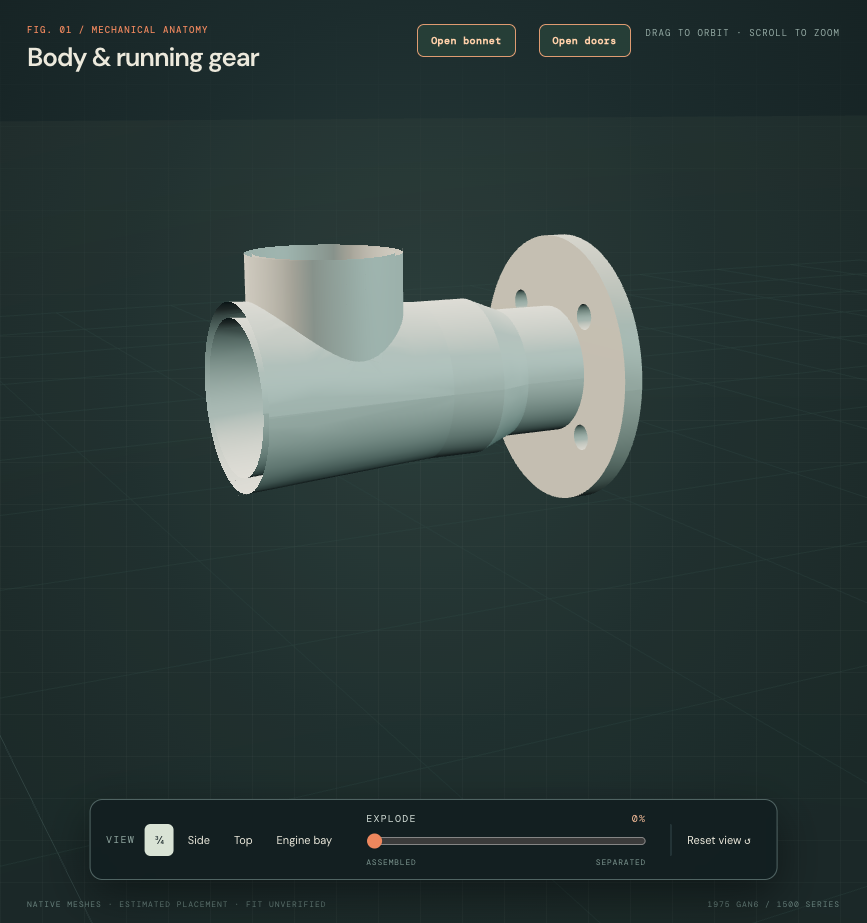
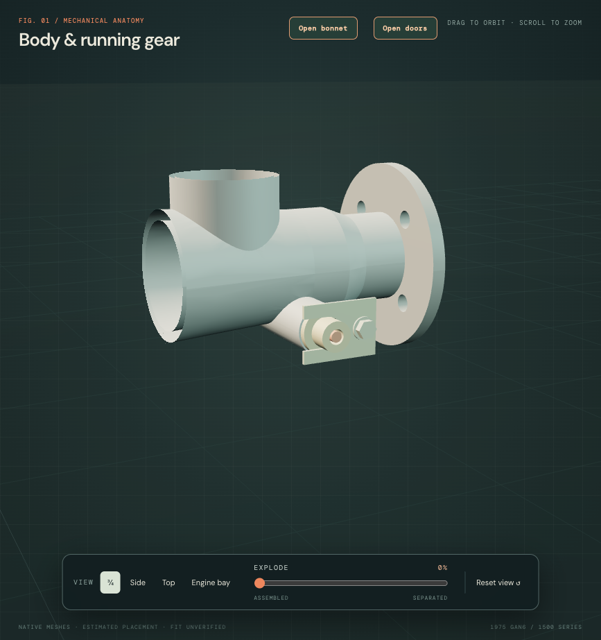
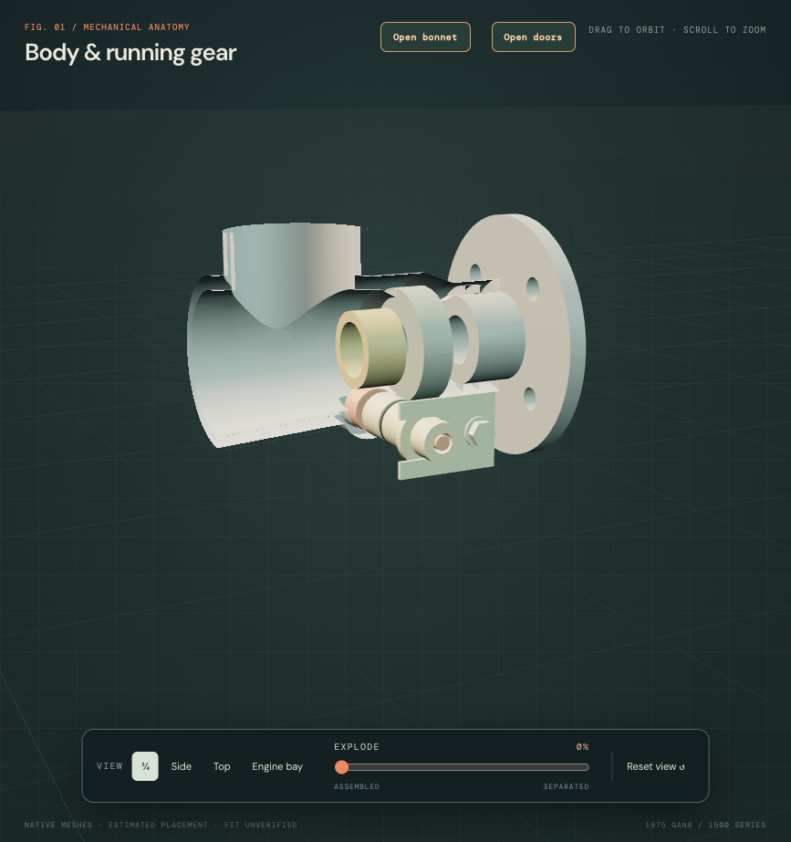
Factory parts81 identifies22G1752 as a six-tooth drive wheel. Parts83 / printed107-C22 separates22G2015 driven pinion (22teeth),13H2792 O-ring,22G2202 sleeve,22G1486 bearing/carrier,CHM1 seal,22G1711 retaining plate,SH604041 screw andWL600041 washer. Workshop printed138 and its printed139 key corroborate the pinion/housing/O-ring and mainshaft wheel roles. These drawings are not dimensioned installation or replacement instructions.
Public supplier photographs of 22G2015,22G1486U,22G2202 and22G1711 support a stepped shaft, grooved carrier, split sleeve and open fork plate. No scale or fitted cross-reference follows from them. Owner IMG_6911/6915 were rechecked: they show front underbody/sump surroundings and do not calibrate this gearbox-tail connection.
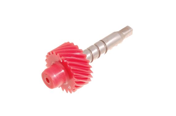
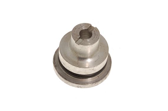
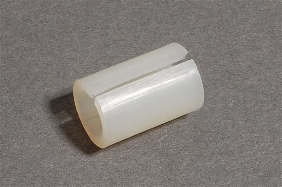
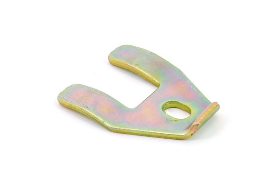
The +X pinion side,−27mm axis offset,10mm smooth wheel radius,12mm width,10/4.2mm carrier outside/bore radii,14mm casting-boss radius,10.5mm passage, groove/seal details and all stations are construction estimates. Smooth envelope tangency explains the architecture, not tooth mesh, handedness, backlash, tolerances, running fit or speedometer calibration. Documentary six/22 tooth counts do not identify the fitted gear pair. Threads, cable square and loaded oil seals are absent.
Keep the North American cable branches separate
Factory parts223 / printed107-H90 shows gearbox-to-service-interval-counter and counter-to-speedometer cables for USA/Canada, with a double-counter/extra-cable California arrangement. The later CanadianAAU3499 listing is not assigned to this1975 car. Its printed6ft3in/160cm wording is numerically inconsistent; neither is adopted as a dimension. The model stops at the estimated carrier’s cable boundary. Fitted counters, angle drive, cable lengths, route and footwell/bulkhead apertures remain unverified.
Workshop scope
The accessible shared gearbox pages establish component relationships, not a complete pinion-replacement procedure. Gearbox removal37.20.01 and the relevant drive-service pages have not been accessed in the available segments. Available UK power-unit instructions are not substituted for missing North American operations. Separation of the pinion, seals, carrier and retaining plate is illustrative; no extraction path, tool access, oil-control procedure or loaded reassembly is verified on this car.
The front cover and its housing seat
The old input-guide tube now has a connected estimated rear stem and shoulder. The housing web has a corresponding open receiver; separate unloaded oil-seal and O-ring comparisons explain the sealing roles. The guide’s front end, input shaft, case and complete release mechanism retain their previous stations.
Factory plate 79 separates a front cover, oil seal and O-ring. MGOC lists separate seal roles, while Paddock describes 122566 as scroll type. These descriptions do not select the actual car’s cover or establish interchangeability. No replacement part is identified by this model.
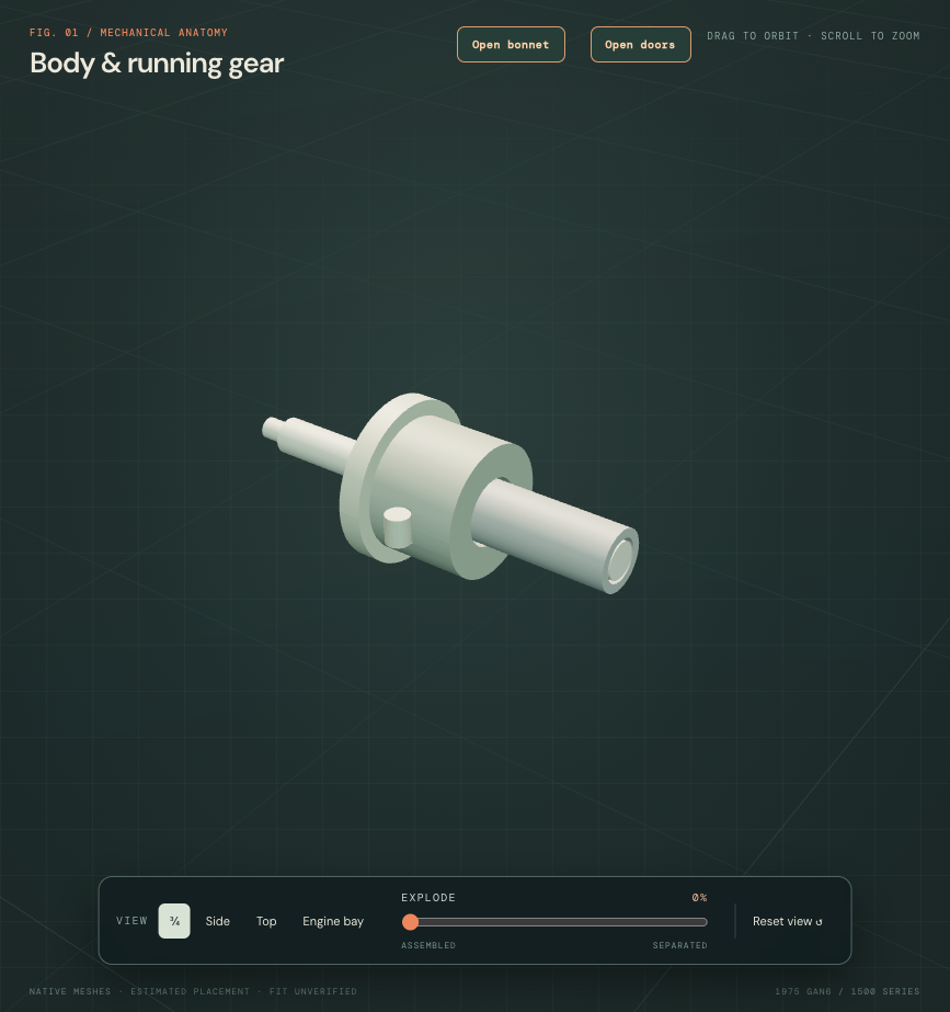
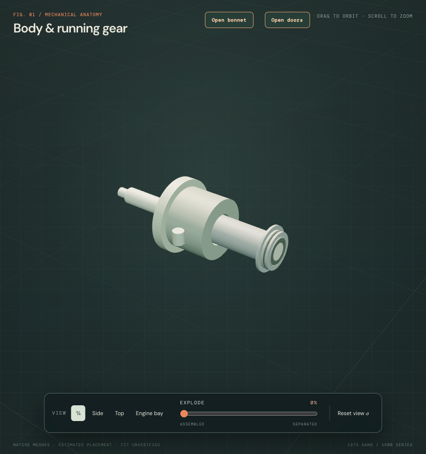
All sections are construction estimates: 22 mm seat radius, 22.2 mm receiver radius, 27 mm shoulder radius and 3 mm shoulder depth. The smooth seal has no functional lip, and the O-ring is unloaded. Illustrated gaps are not press-fit or running-clearance specifications. No scroll helix, oil return, loaded retention or verified extraction path is reconstructed.
Inspect the front cover ↗ · Inspect the conditional seal role ↗ · Native checks ↗
The larger axial gap remains
The release bearing remains 40.3333 mm from the diaphragm in the current drawing frames. That is a reconstruction discrepancy, not actual free play or release travel. No engine, clutch, gearbox or carrier has moved to close it. Accessible workshop pages 138–139 provide the exploded gearbox and key; full removal operation 37.20.01 remains unread. The documented clutch operations remain separate from verified actual-car removal paths.
Current exports: 21 transmission groups / 51 valid STEP solids, and 21 clutch-release groups / 42 valid STEP solids. Native checks establish reference topology and retained neighboring geometry; they do not establish fitted accuracy.
Main-case bays and tail casting
The existing donor side and opposite-side photographs show bounded cast side bays, rounded connecting webs and a reinforced tail. The native model now replaces its isolated sharp side bars with connected rounded borders and webs, adds a lower longitudinal tail web and paired side ribs, and rounds the tail flange corners. The earlier casing dimensions and installed positions remain estimates.
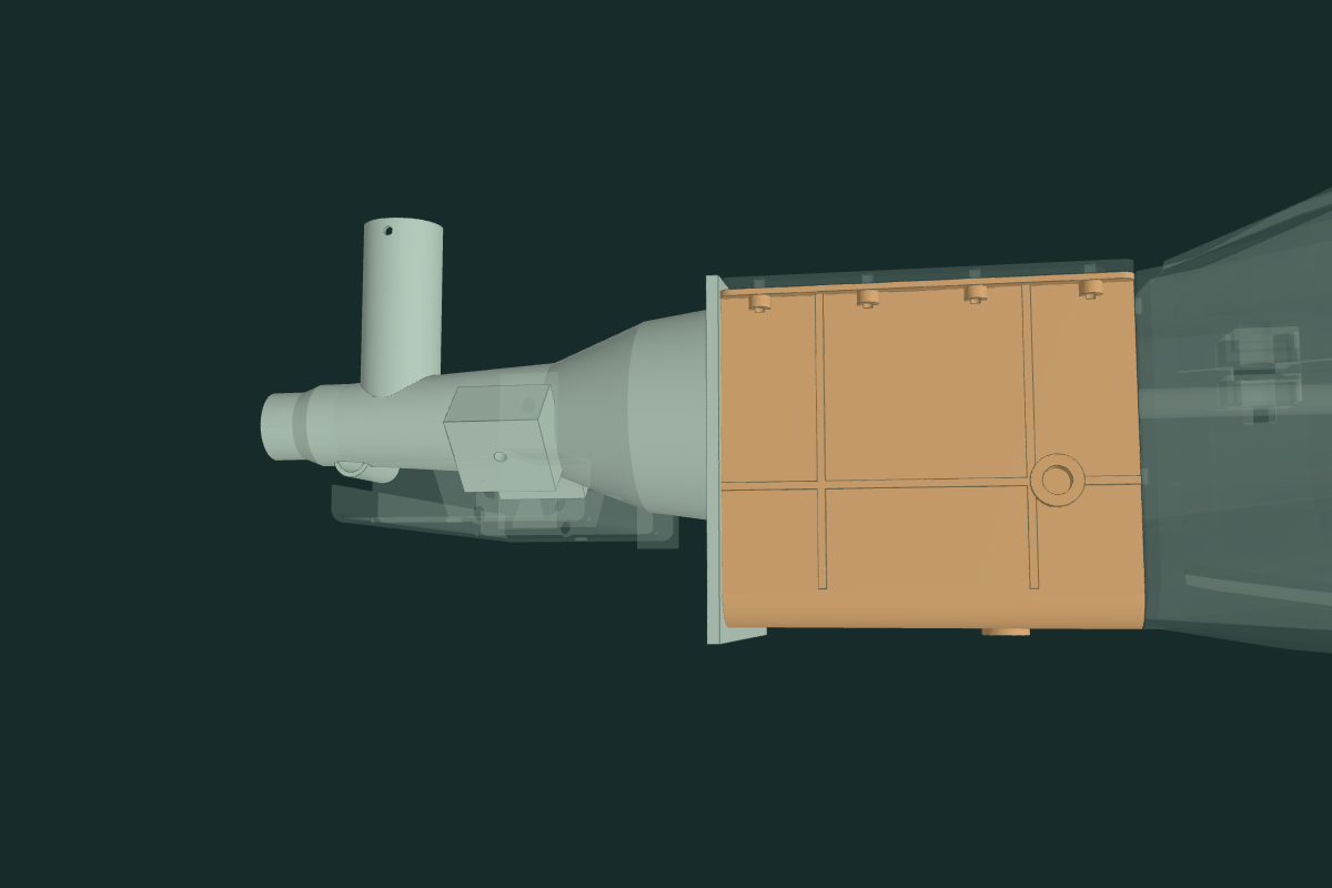
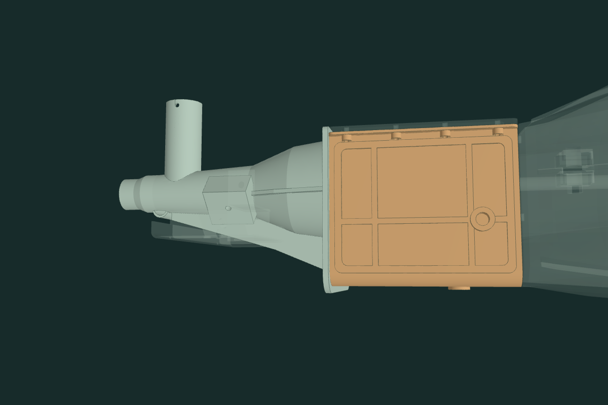
The two castings keep their complete overall bounds and internal case/tail envelopes. Bearing and seal pockets, input/output, selector, speedometer, cover/oil-service and mounting interfaces retain their reference datums. Nineteen other full-source component meshes and native volumes stay. The side-bay layout retains the former divider stations; its symmetry, border sections, lower web, ribs and corner radii are chosen reconstruction geometry, not a traced factory casting or fitted dimensions. The lower tail web is an external solid reference, not a reconstructed oil chamber.
The current full export has 21 groups and 51 valid STEP solids. Each revised casting is one connected solid. Mesh/native volume differences are about 0.004% for the main case and 0.016% for the tail. These check representation agreement, not actual-car accuracy.
The revised tail exposes unresolved support conflicts. Across 56 bounded source comparisons, the selector-rail overlap stays about 2792.68 mm³. New tail/crossmember overlap is about 1569.72 mm³; tail/cradle overlap changes from about 161.30 to 2003.80 mm³. These are static discrepancies between unregistered reference sources, not observed contact on the car. No neighbor is moved and no relief cut is added to conceal them. Loaded mounting, strength, lubrication, operating clearance and replacement access remain unverified.
Earlier reports on this page remain records of their named construction stages. The current casting source is linked here; it does not establish fitted gearbox identity or a verified removal sequence.
Three mainshaft gears beyond smooth rings
Compare the separate reverse-gear revision boundaries ↓
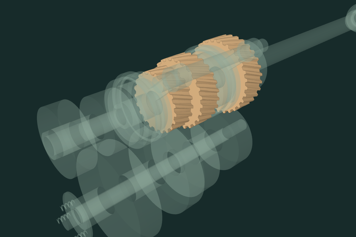
The factory 1500 plate MC0227 identifies first 22G1641, second 22G1816 and third 22G1643. The vendor’s own NOS catalogue lists 30, 26 and 21 teeth respectively. The second-speed listing distinguishes the later, wider-tooth version. These are exact part-number comparisons, not identification of the fitted gears.
The former smooth rings now have open tooth spaces and estimated helical recognition surfaces. The inherited 43/38/32 mm outer radii, 26/24/22 mm widths, 12.5 mm bore radii and 72/136/166 mm axial centers stay fixed and remain estimates. A 3 mm radial tooth depth, trapezoidal flanks, arc widths and a 20-degree helix convention are new construction choices. Fitted hand, helix angle, tooth profile and clocking have not been measured.
All 22 other source parts stay unchanged. The laygear, input gear and reverse-idler roles remain smooth. No mating tooth counts, module, pressure angle, ratios, working mesh, backlash, axial thrust or operating selection are established. The profiles are non-involute and have no root fillets, dogs or synchro-cone detail. No shaft, synchronizer or case is moved to create engagement.
The native validation checks positive solids, STEP/mesh agreement, repeated solid tooth tips and open valleys at three axial sections, bore openness, containment in the previous smooth envelopes and bounded contacts with the fixed source surroundings. Static containment is not evidence of fitted or loaded clearance. The original smooth STEP/JSON remain available as historical construction stages.
Factory plate and first/second roles ↗ · Factory third-gear key ↗ · Vendor NOS tooth counts ↗
This does not establish an interchangeable replacement gear or a removal, refit or adjustment procedure. Legacy native identifiers containing “smooth_annular_envelope” remain stable for existing links; those three shapes are superseded here.
Two reverse-gear changes have different boundaries
The March 1975 factory bulletin 75-D-4 describes a tooth-end revision at Midget gearbox 2270: the mainshaft reverse gear and laygear leading edges became rounded to reduce chipping. It reports unchanged part numbers and individual interchangeability for that modification. It gives no tooth count, nose radius or fitted-car identification.
The Moss catalogue, printed 147 / PDF 205, describes a separate coordinated change at 241363 / 241364:
| Catalog role | Through 241363 | From 241364 |
|---|---|---|
| 1st/2nd synchro assembly | 156911WO | DAM6828SR |
| Laygear | 22G1818 | DAM6475 |
| Reverse idler | 144580 | DAM6826 |
Moss says conversion to the alternative specification requires the three components together. The factory bulletin’s individual-interchangeability statement therefore cannot be generalized to this catalog conversion. Model year, the engine number and a shared service part number do not establish which internals are fitted.
The model retains its simplified laygear and reverse roles. Neither source supplies a located tooth section or selects a fitted set, so no nose radius, mating count, operating mesh or replacement procedure is added. The bulletin heading uses “mainshaft reverse idler”; its body refers to the mainshaft reverse gear. That wording is retained in the reading record rather than silently equated with every later catalog idler entry.
Read the source comparison and limits ↗ · Return to the three catalog-count mainshaft gears ↗