Open the release fork.
Keep the frames explicit.
A rear-web housing with hollow side chamber, separate case gasket/fixings, split boss and mounting/pinch fixings now surrounds the slave exterior, boot, local ports, bored rod-eye joint, pivot bushes/pin, open release fork and carrier/bearing references. Shared construction axes clarify the relationships; they do not establish an installed assembly.
The revised housing, boss and case references no longer overlap in the sampled source pose. Boot/rod contact remains; engine/clutch axial registration is unresolved. The model cannot establish fitted mounting, operating stroke, hydraulic closure or a verified replacement/removal path.
Current revision: grooved slave / locating bolt and separate internal roles ↓
Inspect each interface
Factory roles and supplied evidence
Factory Parts-1977 p. 79 / printed 107-C14 distinguishes 312151 housing, DAM73 slave, 206175 boss, HBZ518 retaining bolt/LNZ205 nut and two HNS507 boss screws. It separately lists 207887 lever, 129410 pivot pin, 129412 tolerance ring, 129358 bushes, 139563 carrier and GRB207 bearing. This is the 1500 arrangement rather than the earlier operating-cylinder layout.
The supplier 206175 photograph shows the split sleeve/flange and pinch-bolt architecture. Dimensions, orientation, ear geometry, holes and fitted identity are not supplied by that photograph. Existing owner evidence gives no calibrated hidden slave/boss/pivot/carrier survey; IMG_6960/6961 master circuit assignments remain provisional. No new direct owner dimensions are applied.
Earlier housing-to-case reconstruction
Factory plate79 separates gasket157690, four HU909 screws and a separate bottom 156336 bolt with copper washer 500464. The earlier construction below represented only the four ordinary fixings; the current five-bolt joint corrects that omission. The RW Auto Classics donor photographs show the rear web around the input guide and a side chamber opening into the main bell mouth. The compact housing now shares the estimated rear-plate outline and starter lobe, replacing both the open cone and later oversized circular silhouette. These comparisons do not identify the fitted housing on this car.
The earlier four-bolt construction used an8 mm rear web after a0.8 mm unloaded gasket layer, an estimated17.4 mm-radius guide passage and four5.2 mm-radius fixing bores at X±65/Y±55 mm. All these dimensions and coordinates are estimates. The gasket plan is a simplified case-face comparison. Case screw lengths/heads are unthreaded display envelopes. No drilling template, compressed gasket, dowel/plug map, front-seal branch, starter mounting or verified removal path follows from them.
Keep the rod datum explicit
Moss PDF p. 53 lists the 1500 rod at 3‑1/16 inches (77.7875 mm) from hole center to end. Another supplier describes the same numeric length as overall. This model follows the explicit Moss hole-center datum, preserving the wording difference instead of treating them as interchangeable measurements. Neither establishes fitted rod identity, insertion, exposed length, free play or stroke.
Construction choices, not fitted dimensions
| Interface | New relationship and limits |
|---|---|
| Housing / boss | A compact asymmetric hollow shell now follows the reference rear-plate outline, replacing the oversized circular mouth. The slave axis and rear case/actuation stations remain estimates. The boss flange is now estimated100 mm wide ×146 mm high, extending rearward from the case plane; revised housing ears meet its front face. Mount rows Y±58 mm and4.5 mm-radius bores stay construction choices. Source nonintersection does not establish a fitted seat or clamp. |
| Split boss / cylinder | A 3 mm split and separate pinch bolt/nut replace the tangential cue. Existing source radii leave approximately 1.6933 mm radial space around the cylinder. This is an inherited estimated gap, not loaded clamp fit, verified clearance or retention strength. |
| Rod / lever | The eye moves 12 mm below the lever plane. The straight rod tilts to an end at Y=0 while preserving the full catalog hole-center length. New 6 mm rod radius and 6 mm lever web are construction choices. Bored eye and lever share a separate pin axis; working travel and actual layers remain unknown. |
| Lever / pivot / carrier | An open frame around the input guide/carrier replaces the invented 55 mm downward bow. Estimated arms join the retained pivot/rod and carrier-pin stations; the housing slave entry continues along the existing axis through the skirt. The 38 mm central opening radius, frame sections and bore/seat shapes are construction estimates. No working leverage, loaded engagement or sweep is established. |
| Carrier engagement | Two engagement-pin comparisons retain the old drawing layout with open lever saddles and carrier seats. Their correspondence to the factory’s one thrust plug, one pin and two dowels remains unselected. No factory quantity map or loaded coupling is reconstructed. |
Current source conflicts
| Sampled pair | Intersection |
|---|---|
| boot rod | 27.6503 mm³ |
The housing, slave boss and new fixing/gasket references do not intersect the current exported main case or guide in the sampled source pose. This supersedes the older housing/boss/gearbox conflicts. The open-fork/slave-entry revision also removes the housing/lever source overlap. Boot/rod overlap remains a reconstruction discrepancy, not actual-car interference or rubber deformation. Neither an empty source intersection nor matching drawing axes establishes fitted clearance, correct adjustment or service access.
Compact housing reconstruction
The factory housing architecture and donor front photograph support a compact lobed mouth around the engine rear plate. The new hollow shell shares the replacement-plate silhouette, with estimated 6 mm wall, a 6 mm-deep front flange and 8 mm flange band. A rear web and slave mounting projection retain the existing case joint. A declared pivot clevis opening accommodates the retained fork eye and arm in the static reference pose; its profile is not a measured casting or verified operating/removal sweep.
Engine, case, shaft and actuation anchors remain. The source housing outer envelope shrinks from approximately622×567 mm to 359×297 mm; the front contour itself is about 326×284 mm. These are reconstruction dimensions under the existing estimated axis spacing, not measurements of this car. The exported housing front face and rear plate have matching outer bounds and no positive intersection, while the selected starter conflicts and 58.3333 mm bearing gap remain unresolved.
Two clutch references still disagree
The engine and whole-car clutch meshes retain their existing estimated transforms. In the shared drawing frame, the engine cover spans Z 485.9–501.9 mm and the whole-car release bearing spans Z 414.8667–427.5667 mm: a 58.3333 mm axial separation between the relevant source envelopes. The omitted engine bearing instead spans Z 466.9–484.9 mm. Neither alternative is a surveyed installed position, so no assembly has been shifted to manufacture contact. These figures are not actual free play, operating stroke or replacement clearance.
The factory first-motion shaft has a reduced pilot role. The source input now ends in an estimated 6 mm-radius,15 mm-long tip while retaining its old endpoint. The matching-family pilot-bush listing supplies 25.4 mm length,12.7 mm bore and19.05 mm outside diameter. At the retained engine export station, the old plain rod intersected that annular comparison by 327.24858 mm³; the reduced tip does not. Their axial intervals still overlap by only 2.0667 mm in this unregistered drawing. No fitted shaft diameter, running clearance, insertion depth, spline engagement or assembled clutch is verified.
The missing rear engine plate
Factory Parts-1977 plate 61 lists 201344 as the gearbox mounting plate, seven plate screws/washers, three rear studs and two separate rear dowel roles. The new engine-frame plate reference supplies the previously absent boundary between block, crank/starter interfaces and clutch housing.
Moss 832-545 and Paddock 201344A are replacement comparisons. Their photographs support the asymmetric outline and two large openings; their alloy material or optional seal configuration is not assigned to this car. The current estimated 132 mm crank/starter spacing scales the image into reference geometry. It is not a measured photo anchor or a factory dimension. The 6 mm gauge, opening sizes and all photographed hole coordinates remain estimates; hole roles and counterparts are unassigned.
The plate retains body Z527.4–533.4 mm. The housing mouth now shares its approximate 326×284 mm asymmetric outline and estimated 132 mm starter axis. Its front face meets the reference plate back face at Z527.4 mm. This supersedes the earlier 567 mm circular mouth and 96.6 mm independent chamber-axis mismatch. The shared curve uses the same uncalibrated image basis; agreement does not establish fitted dimensions, bolt/dowel alignment, loaded contact or useful clearance.
Two selected current engine-builder shapes overlap the plate: starter yoke 2833.559494 mm³ and drive end 9451.796377 mm³. These are source reconstruction conflicts, not installed interference findings or a complete engine-clearance audit. The revised housing also overlaps the selected current starter drive-end shape by 6513.256239 mm³. Engine, starter, flywheel and bearing positions stay. Housing contour and its nominal mouth face now follow the plate relationship; those changes do not close the remaining starter or axial registration gaps. The earlier 58.3333 mm value remains a comparison against the original engine-only flat cover. The current whole-car clamping stack instead leaves a 40.3333 mm bearing-to-diaphragm drawing gap; the release mechanism and engine pose are unchanged.
Factory drawings establish plate and fixing roles; this study does not assign every photographed hole, show loaded attachment or verify a replacement sequence. Display separation does not establish flywheel/starter access, fastener removal order, lifting/support, tool clearance or a withdrawal path.
Workshop boundary and model frames
The eighteen native comparison groups use the gearbox-local millimeter frame, translated once to the body gearbox axis. The engine-only source retains its earlier clutch geometry. The whole-car view now uses a separate flywheel/pressure-plate/diaphragm-cover reference at the unchanged engine placement; its remaining bearing and shaft gaps do not establish fitted registration. The native engine’s duplicate release-bearing mesh remains omitted only from the combined display.
Selection, isolation and illustrative separation distinguish mounting screws, pinch retention, pivot parts, slave/boot/ports, rod-eye pin and carrier/bearing. The slave inlet stays open rather than joining either provisional master. No pressure passage, piston/seal construction, loaded locking, preload, full motion, safe drain/support/release order, tool access or verified replacement sequence is encoded.
Native files and validation
Eighteen source meshes contain thirty-nine positive valid STEP solids with checked volume/count round-trip. Construction checks gauge shared boss, pinch, pivot and rod bores, rod/lever nonintersection and catalog center/end length. Browser checks assess metric frame placement/picking, bore and pin occupancy, isolation, declared display movement, source contacts, links/downloads and mobile layout. They do not verify installed fit or a functional clutch.
The axial gap still needs its own datums
The factory parts plate lists sleeve 139563 and bearing GRB207. The workshop procedures 33.25.10/33.25.12, printed page 134 distinguish the sleeve, bearing and operating lever, including pressing through the sleeve. They do not dimension the installed bearing contact plane or loaded diaphragm-finger plane.
The model therefore retains its 40.3333 mm bearing/diaphragm drawing gap. Resolving it needs a common housing datum for the bearing at rest, the loaded finger height from the flywheel friction face, selected carrier shoulder/press depth and the resting fork/pushrod registration. An older Herald/Spitfire bearing table is not transferred to this 1500. No carrier or shaft has been extended simply to close the picture.
Independent modeling continues with the factory-USA-supported cover/coil relationship using owner photographs already supplied.
Five fixings and the laygear preload relationship
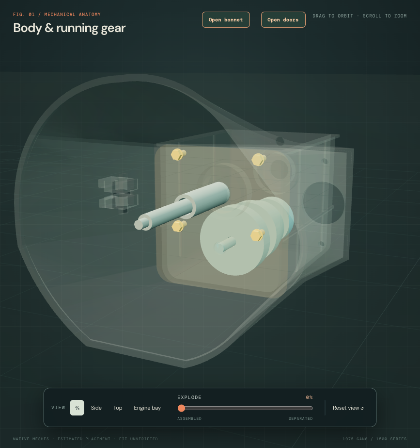
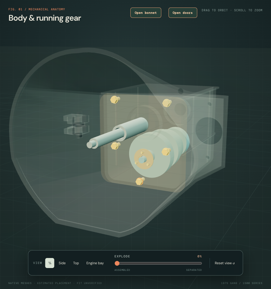
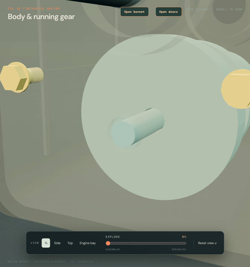
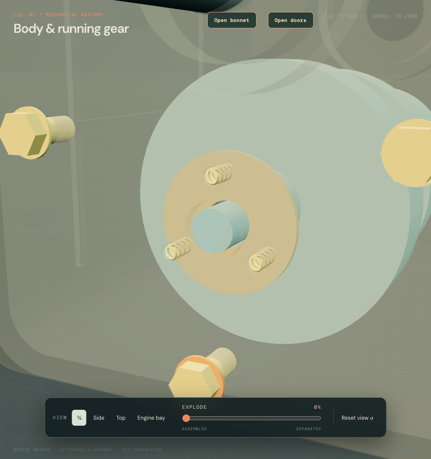
The factory workshop manual adds a missing relationship inside the housing joint: five housing-to-case bolts, a copper washer on the bottom bolt, and three laygear preload springs. The earlier model showed only four bolts and omitted this spring/washer connection. The current native model adds the bottom fixing and separate copper washer, a front laygear thrust-washer comparison and three coils through matching case/gasket passages. The laygear’s smooth front journal extends to the washer reference; existing gear envelopes, case/housing placement and the original four fixing axes stay.
What was actually read
AKM4071/B, printed p. 134, operation 33.25.10, was visually checked. Its title incorporates AKM3267; this accessible shared clutch section is not a substitute for the missing North American engine-removal pages. The gearbox drawing/key on printed pp. 138–139 (scan pages 34–35) identifies the front laygear thrust washer and three preload springs. Factory parts plate 79 distinguishes four HU909 screws, one 156336 bottom bolt, copper washer 500464 and gasket 157690. The gearbox parts plate supports the separate front washer/spring roles. These references do not identify the fitted gearbox or casting on this car.
Documented sequence, with a defined boundary
Operation 33.25.10 requires gearbox removal under 37.20.01 before this housing operation. It then describes undoing the five fixings, retaining the bottom copper washer, removing the housing/gasket and collecting the three preload springs. The release parts include the lever pin, lever, splined sleeve, bushes and slave housing. During refitting, the sleeve precedes the lever and the pushrod passes through the slave housing. This is a summary of the shared factory housing operation, not a complete removal/refitting instruction. The missing North American engine/gearbox sections, actual-car support arrangements, tool access and withdrawal clearance remain unverified. The viewer’s separation slider illustrates component relationships; it does not implement this sequence or prove a removal path.
Estimated geometry, not a preload specification
The original four fixing axes remain X±65/Y±55 mm in the gearbox-local frame. The fifth axis at X0/Y−134 mm, 18 mm spring-axis circle about the retained layshaft axis, 3.2 mm pocket radius, 2 mm washer thickness and 25/8.2 mm washer radii are construction estimates. The smooth front journal extends by approximately 30.87 mm to this estimated washer station. The 12.8 mm displayed coil span, wire diameter, turns and all spring end details are also estimates. None specifies actual free/compressed length, spring rate, preload, endfloat, thread engagement, copper-washer compression, torque or oil sealing. No new owner dimensions were applied.
Native checks cover 51 valid groups across the case, housing/release and internals exports. Forty-three mesh groups remain byte-identical to the preceding revision; five existing groups change and three are added. Five shared fixing axes, three matched spring passages and the reference end-plane relationships pass construction checks. The springs have no positive source intersection with the checked case, gasket, housing, washer or laygear. These results establish this static construction only. The existing boot/rod contact and clutch axial registration gaps remain separate unresolved issues.
A locating bolt through the cylinder groove
The earlier smooth cylinder and outboard bolt did not represent positive cylinder retention. The current model adds a local transverse groove and aligns the boss bore and bolt with it, preserving the cylinder axis, exterior envelope, housing, two boss mounting screws, rod and release mechanism. The split boss remains: the correction concerns the bolt crossing the cylinder groove, rather than assuming a smooth barrel is retained solely by clamping.
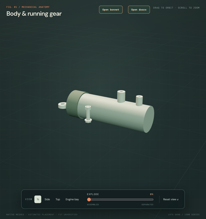
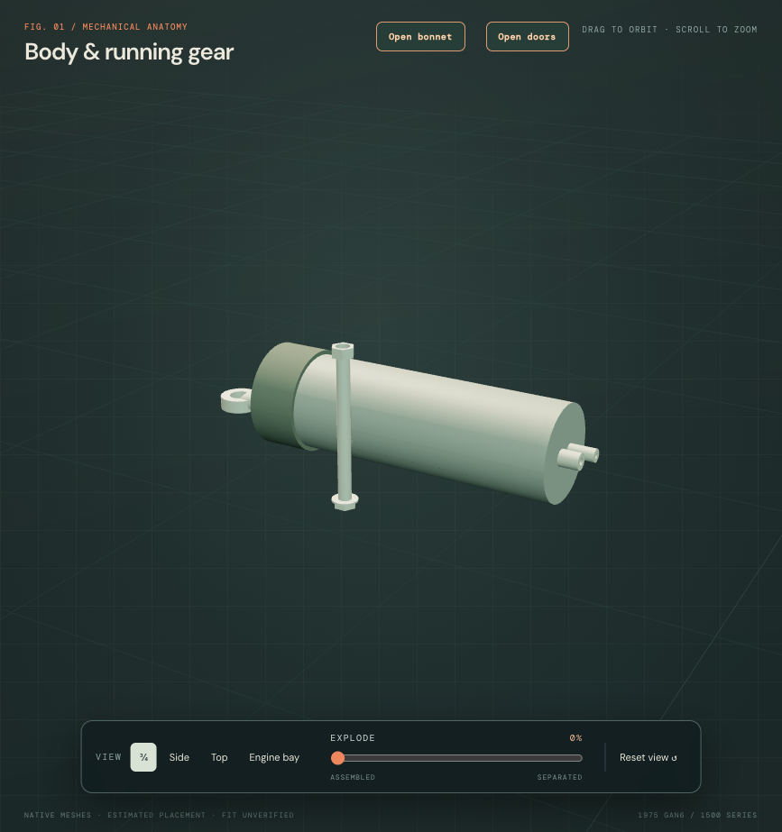
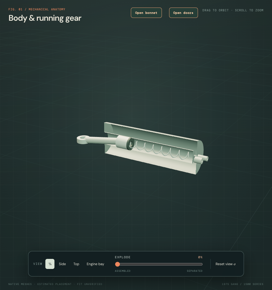
Factory AKM4071/B scan31, printed135, operation33.35.01 explicitly calls for aligning the cylinder groove with the bolt hole. This shared slave procedure is beside a separately marked USA pedal procedure; the USA pedal instructions are not assigned to the cylinder. The manual’s illustrated end connections and Rimmer GSY107 photograph support rear-facing connections and a local side groove. Neither source dimensions their installed orientation or identifies your fitted cylinder.
Printed136, operation33.35.07 / SNC040 distinguishes the dust cover, plunger, spring and seal. Separate selectable internal references now represent those roles. Moss180-705 supplies a 7/8in (22.225mm) nominal bore comparison, replacing the previous arbitrary38.9467mm hollow opening. This is a supplier dimension, not an owner measurement or identification of the fitted DAM73/GSY107 variant.
The inherited57.5733mm exterior diameter and169.3333mm barrel length remain uncalibrated construction estimates. They were not derived from the nominal bore or supplier photograph. Groove radius4.5mm, bolt diameter8mm/display length90mm, port positions/drillings, plunger radius10.9mm/length22mm, cup profile and spring span/turns are illustrative estimates. The90mm display bolt is not the supplier catalog’s5/16UNF×2¼in fixing. No running fit, loaded seal, free play, spring load or hydraulic performance is established.
Documented service relationship
Factory33.35.01 disconnects the hydraulic pipe, removes the locating bolt/nut/washer and withdraws the cylinder. Refitting centralizes the pushrod, inserts the cylinder, aligns its groove with the housing bolt hole, reinstalls the locating fixing, reconnects the pipe and calls for bleeding under33.15.01. This is a paraphrase of the accessible factory procedure, not a complete replacement instruction or a verified removal path on this car. The model’s separation slider is illustrative; actual access, support, tools and pipe movement remain unverified.
Native checks verify an open nominal bore and two rear passages, the bolt occupying its local groove without positive intersection, and cylinder/bolt interference in illustrative±10mm axial-displacement samples. Those samples explain the retaining role; they do not establish permissible motion, extraction clearance or tolerances. The existing boot/rod overlap and bearing-to-diaphragm registration discrepancy remain unresolved.
New conditional front-cover seat and separate sealing roles ↗ · The housing receiver is estimated; the fitted seal variant and bearing-to-diaphragm registration remain unresolved.
Flared housing and cast-web comparison
The existing supplier donor photographs show a flared hollow casting with external reinforcing webs. The model now adds a shaped exterior between its retained end bands and three visible-side web references. It replaces the straight outer-loft appearance while keeping the original internal envelope, mouth, rear web and all clutch interfaces. The other twenty clutch component meshes stay.
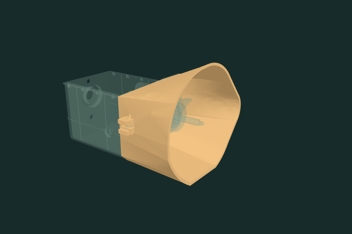
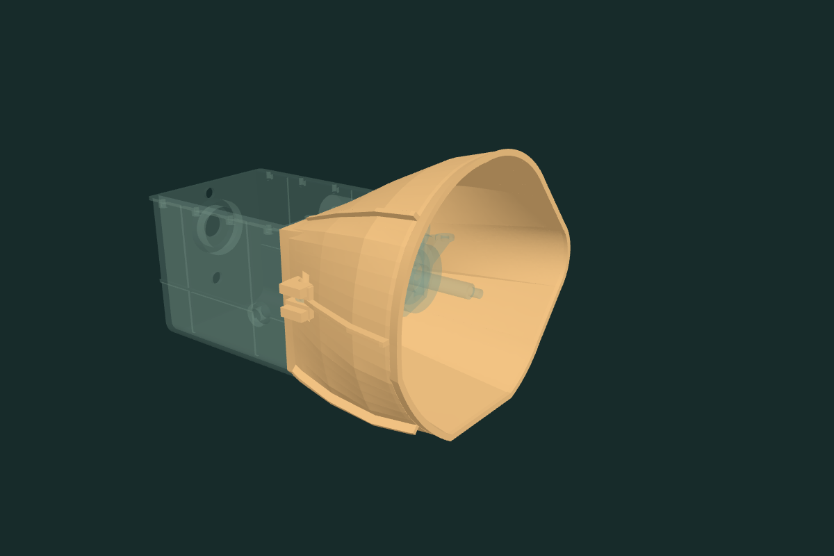
The section positions, up to 10 mm outward bow, three-web map and 6 mm web width are construction choices from unscaled photographs. Sixty-four radial samples approximate each intermediate exterior section. The original interior stays, so the estimated wall varies; this does not establish normal casting thickness, mass or strength. The donor listing does not identify the housing fitted to this car.
The current full STEP contains 21 groups and 42 valid solids. The changed housing remains one solid; twenty other component meshes and native volumes are held. Its display mesh differs from the native solid’s volume by about 0.04%; this checks representation agreement, not actual-car accuracy. Ten bounded comparisons with the gearbox, footwells and front exhaust retain zero material overlap. These are static model checks, not fitted clearance or proof of working fork travel. The existing 27.65 mm³ boot/rod reference overlap remains explicit. Actual body/engine/gearbox registration and replacement access remain unresolved.