Support the pedals.
Expose the shared joints.
An open thin box, cover and uncompressed seals now surround separate bored pedal hubs, bushes, shared pivot bolt/retainer and forked pushrod/clevis-pin comparisons. The cylinder envelopes and outlet cues retain their provisional roles.
Existing evidence, separate from construction
Factory PDF p. 163 distinguishes CHA375 box, CHA333 cover, AHA8075 shared pivot bolt, bushes, return spring and separate seal/gasket roles. Its eight body screw/washer roles supply a count, not a fitted hole map. P. 154 preserves clutch-master change points, while p. 164 provides a dual-line brake-master comparison. Neither identifies these fitted cylinders or their pipe destinations.
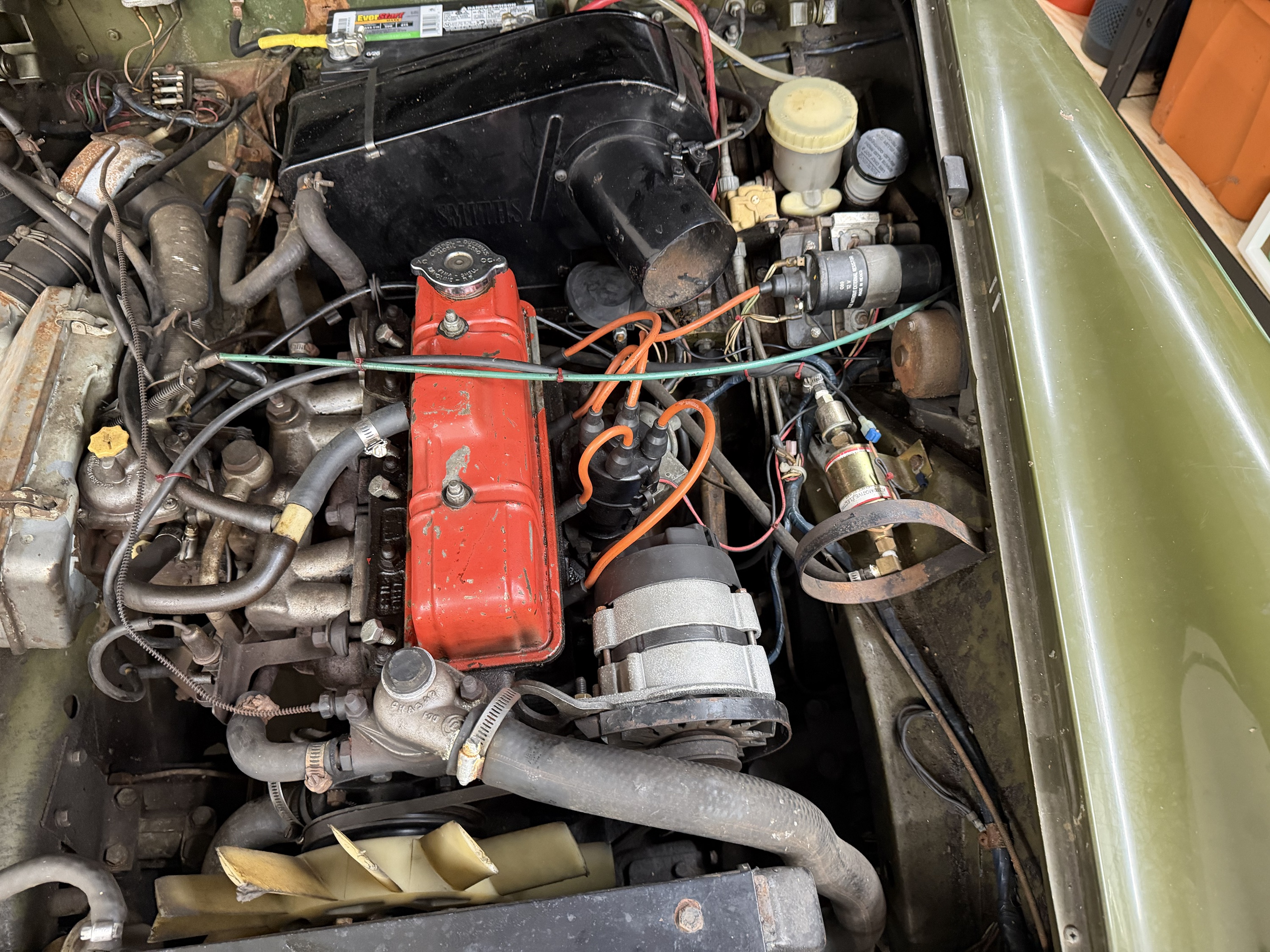
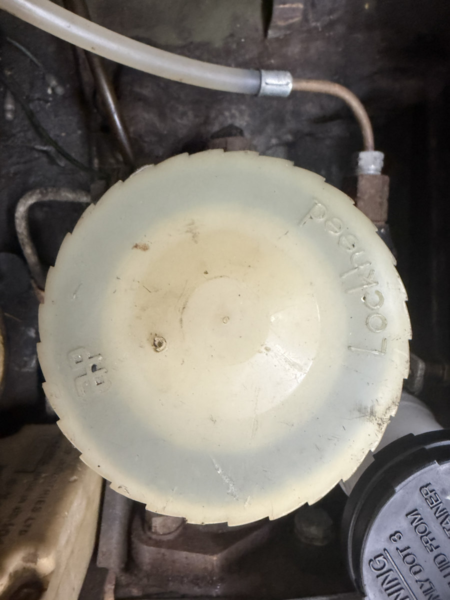
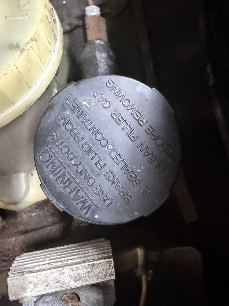
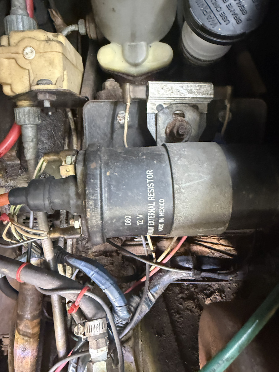
IMG_6855, IMG_6960, IMG_6961 and IMG_6962 establish the reservoir/cylinder surroundings, pale LOCKHEED cap, black warning cap and nearby equipment. They do not calibrate the hidden pedal box or trace the circuits. No direct owner dimensions are newly applied.
The supplier CLZ513 listing supplies a nominal 5/16 × 7/8 inch pin comparison (7.9375 × 22.225 mm). Its earlier-car catalog context is not applied as the whole 1500 configuration; factory and supplier references independently list the same clevis-pin role. All modeled fits and other hardware dimensions remain estimates.
Formed housing, rails and thin cover
Factory p. 163 and the photographs of RW18356, documented by its seller as a 1976 donor, support folded forward mounting rails, shaped sides and a separate thin formed cover. This reference replaces the tall plain crate/thick lid with a sloping rim, a 2 mm projected-gauge cover with edge returns, and 165 mm forward channel extensions. These dimensions, the rear roof level and all new sections are unscaled estimates; the donor is not identification of your car’s assembly.
The donor front face also contradicts the old vertical master fixing rows. The box, rounded master flanges and fixing envelopes now share an inclined estimate: inherited 80 mm center separation, estimated −45° clocking and 4.5 mm-radius bores. Neither separation nor exact angle is measured from the donor or owner car. Two additional rail-end holes are unassigned reference roles; the retained eight base holes do not establish a fitted hole count or map.
Pedal, pivot, clevis, pad, master input and main base coordinates remain unchanged. The revised shell still intersects the estimated column in six sampled pairs, including shaft/cover 2455.6655 mm³ and sleeve/cover 1767.0131 mm³. The thinner source cover reduces the former solid-lid overlap; it does not establish clearance. Fitted body support, mounting correspondence, column registration and replacement paths remain unresolved.
What the model now distinguishes
| Relationship | Construction and limits |
|---|---|
| Housing / body | Thin shaped side/forward sheets, sloping upper rim and folded forward channels replace the old plain box. Eight retained base bores and two unassigned rail-end holes remain estimates. The separate lower gasket is uncompressed; no matching body holes, hidden attachment layers or loaded support are inferred. |
| Cover / seal | A 2 mm projected-gauge sloping skin and four edge returns replace the 15.24 mm solid lid. A separate estimated 0.8 mm seal lies on the new rim; cover profile, screws, loaded sealing and withdrawal clearance remain unverified. |
| Pedals / pivot | Retained hub and pad center stations define new 6 mm pendant webs, bored hubs, separate bushes and shared shaft/retainer envelopes. Shaft/bush fits, pedal ratio, pad sections and alignment remain estimates. No spring, stop, switch or working articulation is reconstructed. |
| Pushrods / clevises | Fork cheeks straddle each bored upper pedal eye on a shared pin axis. Pin heads, retention holes, washers and transverse retention envelopes are separate. Old solid rod/clevis/pin cues in the master groups are removed. The front rod endpoint remains the old drawing boundary, not verified piston engagement. |
The pale-cap and black-cap reservoir/cylinder/flange/boot and outlet envelopes remain provisional. The native pedal assembly does not establish bore size, piston/seal construction, fluid, stroke, free play, brake balance or slave connection. No pipe is joined by inference.
The left footwell body platform now supplies the previously absent body counterpart beneath the retained base gasket, with a projected central mouth and eight shared reference bores. This body reconstruction holds all pedal, master and steering geometry. Its dimensions and joint remain estimates; the column/housing/cover conflicts are unresolved, and coincident gasket/body planes do not prove loaded support or actual fit.
Workshop boundary
Selection and illustrative separation distinguish box, cover/seals, pedals, pivot parts, rods and pin retention. Shared bores support understanding these relationships. They do not prove fitted access, loaded retention, safe adjustment, spring release, a disconnection order or a verified replacement/removal path. Actual master mounting hardware, box-to-body support and surrounding clearances remain unresolved.
No operating pedal movement is simulated. Catalog pin dimensions and open construction gauges cannot establish safe bearing, wear, free play, force or brake/clutch operation.
Native exports
Separate master mounting, reservoirs, boots and local outlet comparisons ↗ now expose shared estimated flange/box bores. Cylinder identities, bore dimensions and hydraulic destinations remain unverified.
Fifteen source meshes contain fifty valid STEP solids. Construction checks verify open pedal pivot and clevis bores and nonintersection between the new pedal and fork. Viewer checks assess metric placement/picking, shared bores and pin occupancy, separation ownership, study/download links and mobile layout. These checks do not validate a fitted linkage or hydraulic system.
The cover also carries the coil
The factory USA clutch-pedal procedure33.30.02, printed page135 removes the pedal-box cover with the ignition coil after the specified disconnections. Owner IMG_6855 and IMG_7040 show the coil, strap and adjacent master cylinders. The previous short cover never reached the retained coil reference.
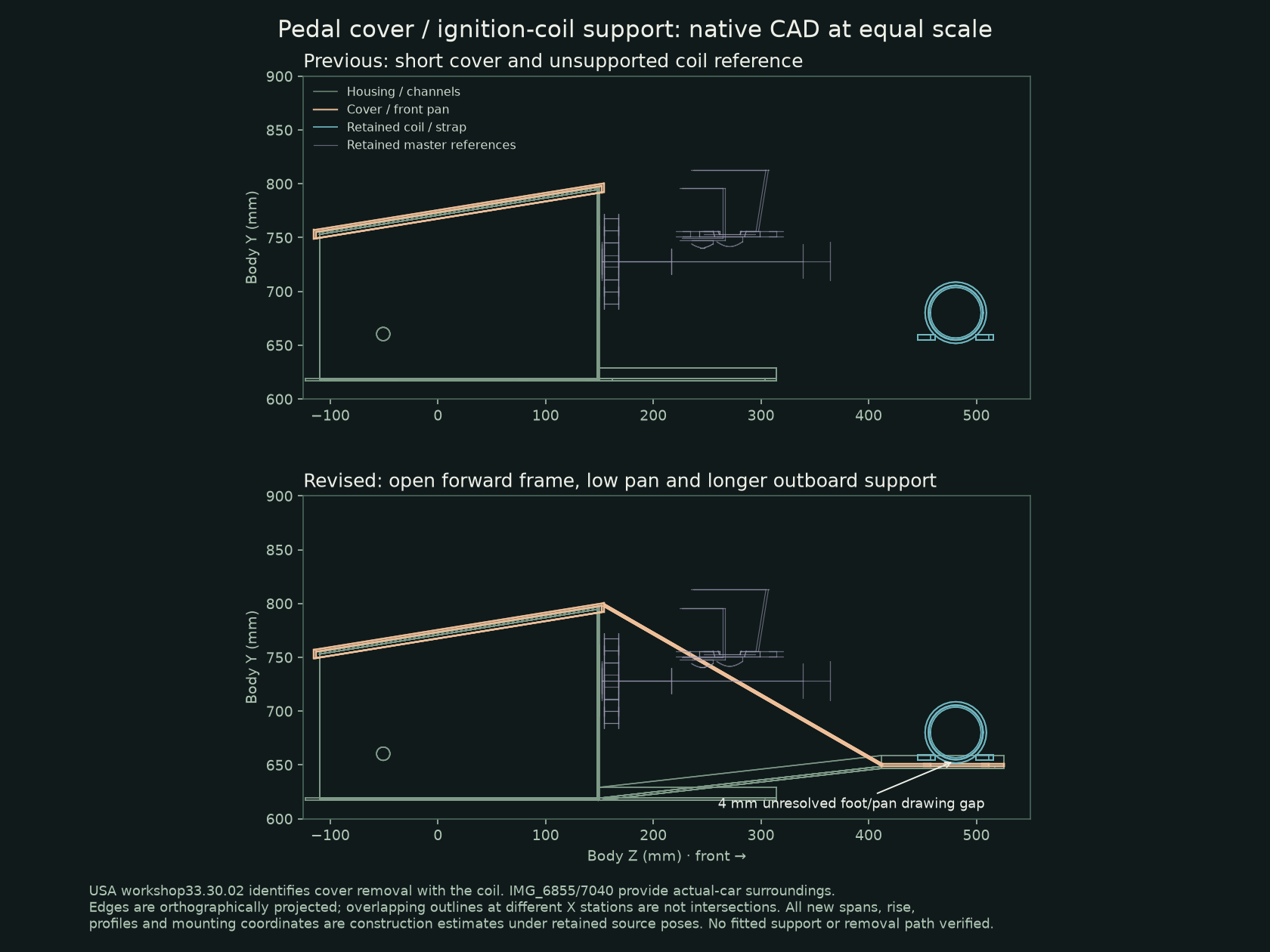
The revised cover has descending side bands around an open master-cylinder region and a low front pan, with a longer outboard support channel. Rear housing, master mounts, pedal/pivot/clevis stations and the original coil meshes stay. The pan uses the existing estimated coil-foot axes for two plain holes. A 4 mm foot/pan drawing gap remains; the short screw cues do not establish engagement. The cover, pan and bands form one connected native solid. Thirteen other pedal source groups keep their geometry and meshes.
The inboard channel retains its earlier 165 mm end. Extending it crossed the unregistered steering shaft, so no fitted notch or alternate route has been invented. Existing column/box/cover contacts remain. The scoped export audit also finds positive pan/support volumes against left wheelhouse panels; those are unresolved source-registration conflicts, not a loaded joint or fitted clearance. The new pan and support do not resolve body registration, hidden attachment, loaded seating, support strength, screw/washer/nut identity or a verified withdrawal path.
Select the cover and forward pan ↗ · Select the retained coil ↗ · Read scoped native checks ↗
The whole-car explode view gives the coil and cover the same illustrative offset. This reflects the factory service grouping; it does not animate a removal procedure, disconnect wiring or simulate flexible leads. The factory ballast-lead instructions describe its reference installation. The owner coil reads “WITHOUT EXTERNAL RESISTOR”; its wiring and electrical compatibility remain unverified.
The factory instructions also distinguish pedal-box body fixings, pivot withdrawal and retained pipe clips. Those roles do not establish the actual bolt map, tool access, hydraulic branch or support arrangement in this model. Use the complete applicable procedure for work on the car; this page connects modeled relationships to its reference operations.
The missing driver input
The whole-car reference previously had brake and clutch pedals but no accelerator assembly. Factory parts plate 152 lists CHA496, a 1500 LHD pedal with integral lever from GAN6-154101 onward, with two HZS404 screws and two LWZ204 washer roles. This is a catalog comparison; the supplied photographs do not identify the hidden fitted pedal.
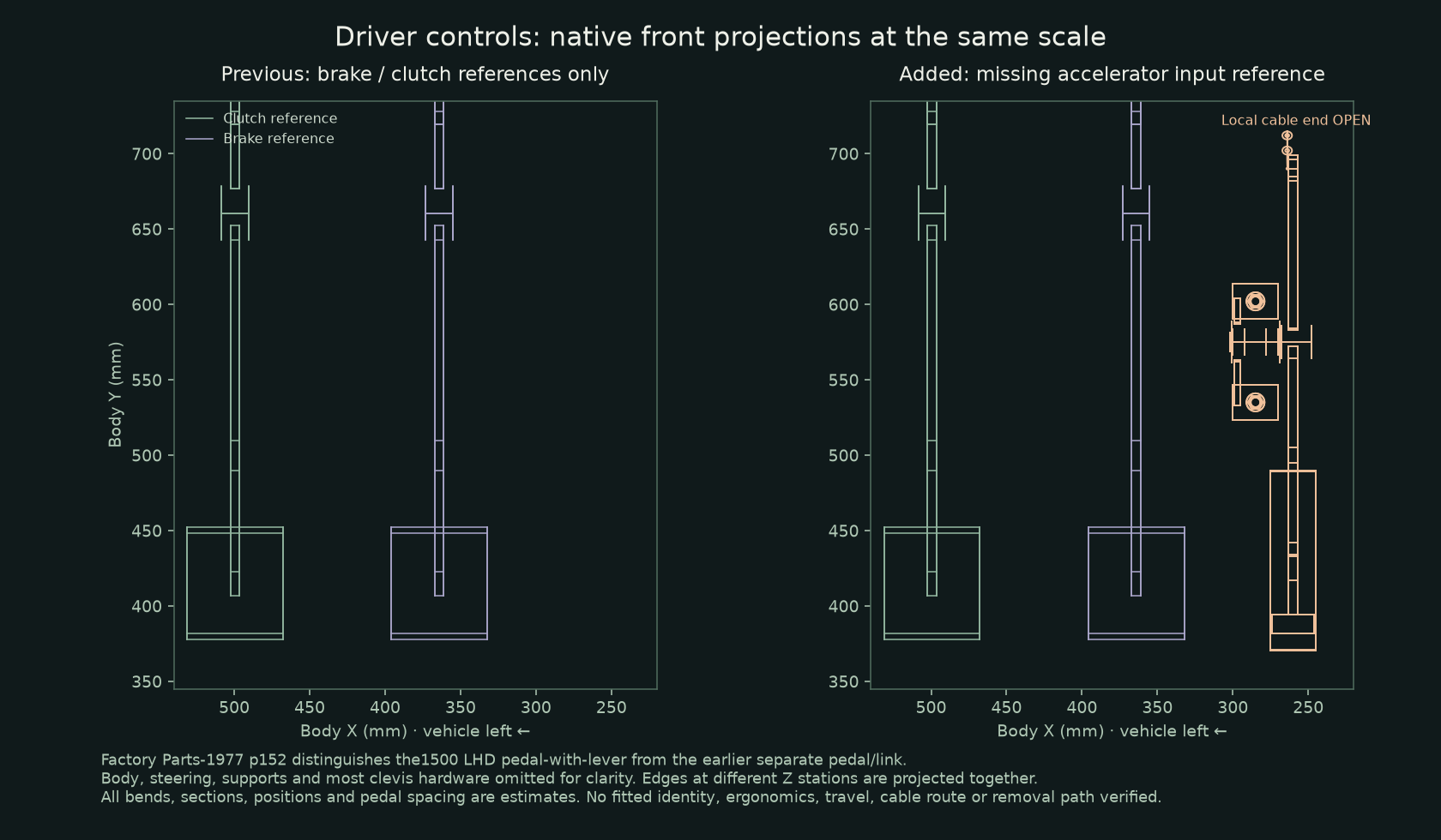
The new source contains a bent metal pedal and integral lever/shaft, a two-foot pivot-carrier envelope, two unassigned bush roles, two mounting screw/washer roles and a short local wire/sheath. The pedal and carrier are each one connected solid. Their bores and source nonintersections explain the mechanical boundaries; they do not identify actual serviceable bush kits, bearing fits or fitted brackets. The generic factory illustration does not establish a handed bend or dimensions.
The earlier AHA6256 pedal and AHA6255 separate link are not added to this 1500 role. RHD-only BHA5357 pin and BHA5358 clip are also excluded. CHA405 non-California and CHA485 later-California cables remain unselected. No additional pedal return spring, stop or cable adjustment is inferred from the multi-configuration parts plate.
Select the accelerator pedal ↗ · Inspect its carrier envelope ↗ · Inspect the open local cable boundary ↗ · Compare the independent carburetor-side linkage ↗
No continuous cable is drawn across the bay. The two independently estimated endpoints are about 771 mm apart in a straight line; that chord is not a cable length, route or purchasing specification. The hidden body receiver, bulkhead passage, clips, termination, slack, spring/stop assignment, loaded pull and pedal travel remain unresolved. No body holes are cut to force agreement, and no throttle actuation or verified removal path is simulated.
Download native accelerator reference ↗ · Read geometry and limits ↗ · Read native/mesh checks ↗
Selected checks find no source overlap with the existing pedal-support, steering-rack/column, front-footwell or cabin-understructure files. Those surrounding sources are unchanged; their earlier mutual conflicts remain. In particular, the estimated steering centerline crosses the existing pedal-box roof and master face. The current photographs obscure the common hidden mounting datums, so neither tube shrinkage, a fabricated steering kink nor a box notch is accepted as the fitted solution.
The factory two-fixing relationship is a service boundary to inspect, not a complete replacement procedure. Support, cable release, actual fastener access, retained parts, full-throttle/return checks and fitted adjustment require the applicable procedure and actual installation. Explode movement is illustrative.