From master
to wheel.
Ten selectable pipe/hose references connect the provisional brake-master drawing to the four brake-corner drawings through a pressure-failure warning-unit comparison and rear axle tee. The front and rear circuit branches remain distinct in the declared comparison graph.
IMG_6960 and IMG_6961 were re-viewed: their cap markings and local line portions do not establish the complete circuit. The pale-cap unit retains its provisional brake role. Factory architecture supplies the network; all routes, port assignments, bends, hose diameters and fitting/mount shapes are estimated. No actual master-outlet pairing is promoted to confirmed.
The comparison graph
The warning-unit exterior has five estimated connection points. Its internal passages, shuttle, switch contacts and failure behavior are not modeled. These graph branches describe factory topology, not a verified port map or pressure simulation.
Inspect the modeled chain
Factory evidence and differences
Factory PDF plate 166 lists the GAN6-154101-on pipe relationships and prints a 4.762 mm outside diameter. That documentary diameter is applied to rigid pipes. Copper coloring distinguishes the drawing; it does not identify the fitted pipe material.
| Factory pipe comparison | Listed length | Model use |
|---|---|---|
| Master → warning unit, front/rear | 15.5 / 17.5 inches | Topology only; port order and bends estimated |
| Warning unit → right/left front hose | 41 / 10 inches | Separate branches; no forced curve lengths |
| Warning unit → rear hose | 81 inches | Estimated body/tunnel route |
| Axle tee → right/left rear brake | 22 / 30 inches | Estimated routes around the axle shell |
These listed lengths are catalog comparisons, not measurements of this car and not lengths of the new curves. The geometry is not a pipe-cutting, bending or fabrication template.
Plate 167 lists the rear three-way connection 3H2424, two front flexible hoses and one rear hose. It changes the pressure-failure assembly to AAU2583 at GAN6-166304 and hose references at GAN6-162565. This model does not identify which versions are fitted. Bracket positions, clips, unions, threads, flare seats, banjos and port identities remain unresolved.
Connections to surroundings
The front routes add obstacles near the inner bay and front frame. The rear body route follows an estimated tunnel-side path; its flexible section crosses to the estimated axle tee. The rear pipes terminate at existing cylinder inlet cues. Front hoses meet assumed inboard caliper faces. Endpoint coincidence is a drawing relationship, not a proof of correct inlet position, a sealed fitting, hose slack or clearance through steering and suspension travel.
Select and isolate lines to follow the connection chain against the body and corner references. General separation leaves the network fixed, so separated components can leave gaps; hoses do not stretch or simulate motion. The factory parts list does not establish a removal sequence, supported condition, pipe access, fluid compatibility, bleeding procedure or verified replacement path. Those procedures remain unresolved for the actual fitted circuit.
Hollow native routes and open union references
The seven rigid-pipe and three flexible-hose comparisons now export as native hollow solids. Their original centripetal centerlines,control points and endpoints remain. Each route has two separate open union sleeves following its end curves. The warning-unit exterior,rear tee,body-hose brackets,master outlets and wheel-end references stay at their previous stations.
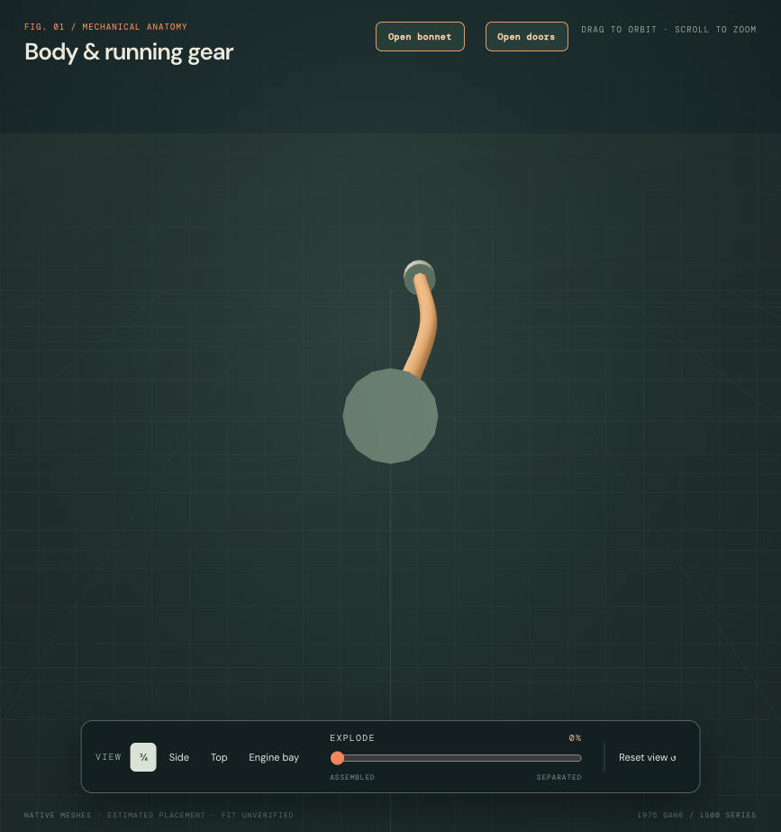
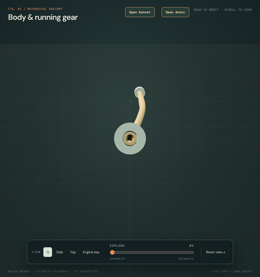
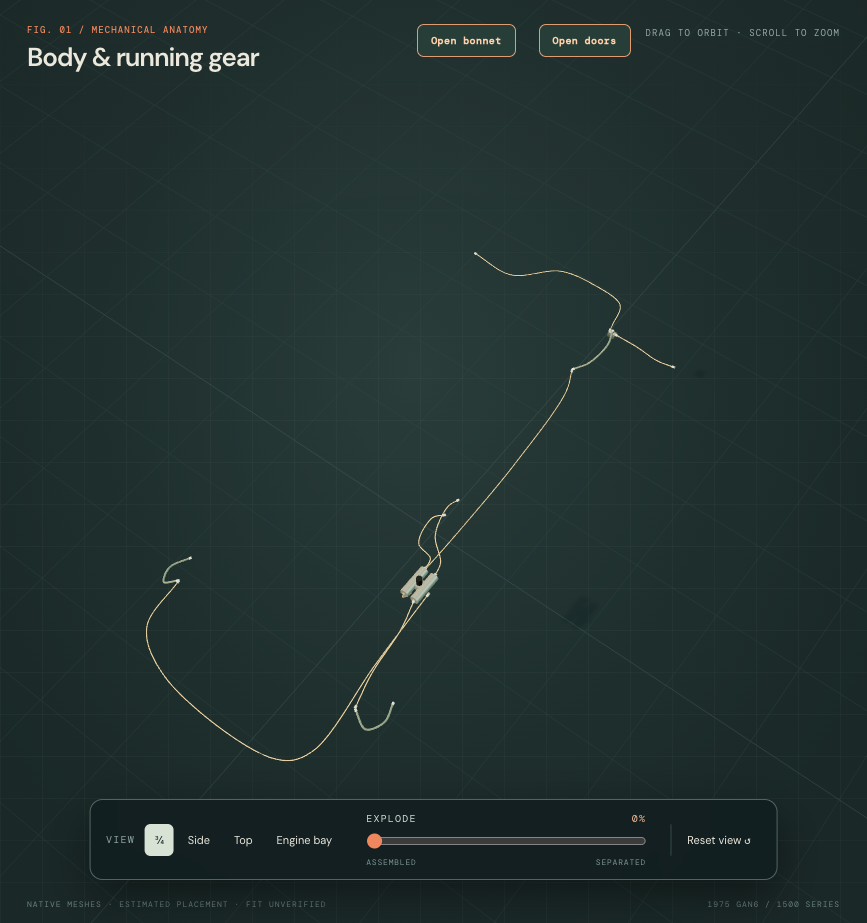
Factory PDF166/107-G26.02 supplies4.762mm pipe outside diameter and the two master feeds,front branches,rear body pipe and two rear wheel-pipe roles. PDF167/107-G28 supplies hose,tee and warning-unit branches. The 1mm rigid-pipe radial wall,3.2mm hose bore,9mm hose outside diameter and12mm curved union sleeves are estimates. Union sleeves have5.5mm outer radius and a0.25mm radial display gap to the pipe;no thread,flare,seat or loaded sealing is modeled. Copper colour remains a display choice,not fitted material identification.
The factory pressure-failure unit changes from13H5905 toAAU2583 atGAN6-166304,and hose references change at162565. Neither threshold identifies this car's fitted parts. Hollow pipes do not supply the missing warning-unit channels or prove master outlet order,circuit assignment,pressure continuity,material/fluid compatibility,serviceable bend radii,flex travel,clip locations or actual clearance.
Native checks cover20mesh groups/30positive valid STEP solids,open endpoints and wall witnesses,plus1,010centerline samples compared with the actual local viewer curve implementation. The original circuit graph and nearby native sources remain unchanged. Those checks establish reference construction only. Applicable complete North American brake replacement/bleeding procedures and actual removal paths have not been verified.