Two reservoirs.
Trace them before service.
IMG_6960–6961 show two nearby hydraulic reservoirs: a larger pale LOCKHEED-marked cap and a smaller black cap with a brake-fluid warning. Their positions make brake and clutch roles plausible, but the photos do not trace either hydraulic line to its destination. Record the actual circuit on the car before opening a reservoir, buying a cylinder or adding fluid.
Identification is still provisional
The larger pale reservoir is the likely brake-master reservoir and the smaller black-capped cylinder is the likely clutch master. These are photo-based hypotheses. Moss lists the Midget brake hydraulics separately from its clutch hydraulics; catalog architecture alone cannot prove which cap is on which circuit of a modified car.
What the photographs show
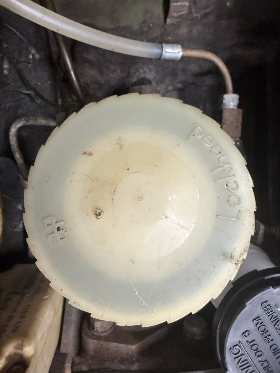
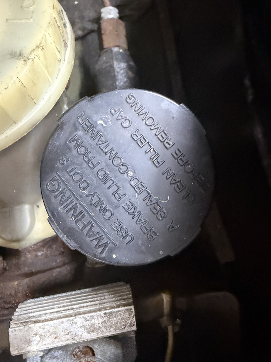
Record before choosing parts or fluid
| Question | Evidence now | What to verify on the car |
|---|---|---|
| Which circuit? | Two independent-looking reservoirs; positions suggest brake and clutch masters. | Trace each master-cylinder outlet line to the brake distribution hardware or to the clutch slave. Take a continuous sequence of photographs from the reservoir to its destination. |
| Which cylinder? | Cap color and visible housing only. Moss lists a dual-line brake master for the 1500 and a separate clutch master. | Read casting or stamped numbers, count outlet ports, photograph mounting and pipe fittings, and measure bore only as part of an appropriate overhaul. |
| Fluid and condition? | The black cap is embossed DOT 3; levels and actual fluid cannot be reliably read from these top views. | Record the applicable manual specification, any service history and the fluid already in each system. Inspect level, wetness and pedal behavior separately; investigate low level or leaks before a road test. |
Ten-minute parked inspection
- Park level, engine off and key out. Photograph both caps and the complete master-cylinder area before moving anything; protect nearby paint from hydraulic fluid.
- Follow each rigid line by sight. Photograph its next connection and continue until its brake or clutch destination is established. Do not loosen a line just to identify it.
- Record any casting number, reservoir shape, outlet count and visible level for each master. Keep “unknown” where a line disappears under the car or behind a panel.
- Check for wetness, corrosion, chafing and unsupported pipes at the reservoirs and accessible connections. Photograph findings before cleaning them.
- With the car stationary, record brake and clutch pedal feel separately. A sinking brake pedal, leak or uncertain brake condition calls for diagnosis and repair before driving.
- Use the verified cylinder identity, the applicable factory procedure and known fluid history before ordering rebuild parts or adding fluid. The wording on a possibly replaced cap does not identify the existing fluid.