Separate the interfaces.
Keep circuit roles provisional.
Two former solid master groups now separate into external bodies and bored flanges, hollow supply tanks, cap skirts, hollow dust boots, mounting hardware envelopes and open local outlet fittings. Existing axes, outside bounds and network endpoints remain estimated source datums.
Evidence and variant limits
IMG_6960 shows the pale LOCKHEED cap and a local union/pipe context; IMG_6961 shows the black warning cap. IMG_6962 and IMG_6855 locate the reservoirs among adjacent equipment. They do not identify the complete circuits or calibrate flange geometry. No new direct owner measurement is applied.
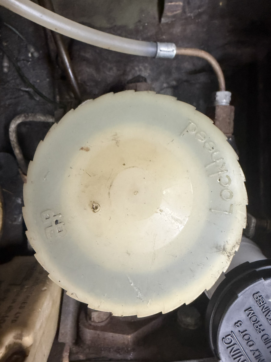
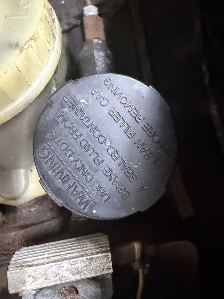
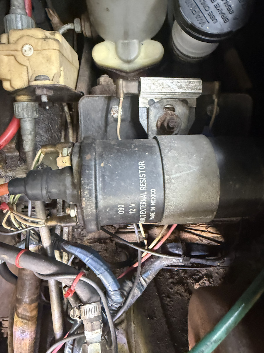
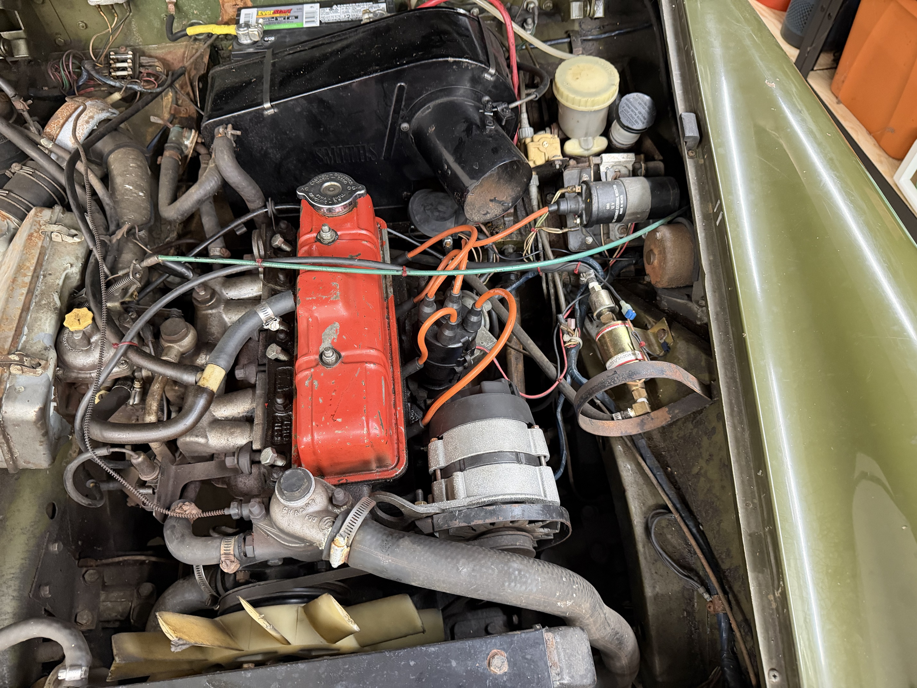
Factory PDF p. 154 separates clutch master, cap, pushrod, hydraulic adapter and mounting screw roles, with North American master changes at GAN6-167343. P. 164 supplies dual-line brake body, supply-tank, cap, boot and outlet-adapter architecture. These remain comparisons, not fitted identities or proven pale/brake and black/clutch assignments.
The 21K8564/ACB9641 catalog adapters are hydraulic pipe fittings, as the supplier listings also distinguish. They are not mounting brackets. The local outlet shapes do not select either adapter, a thread standard or a flare/valve seat.
Shared mounting geometry
Each rounded flange now shares an inclined estimated row with the pedal-box forward face: inherited 80 mm separation, estimated −45° clocking and 4.5 mm-radius bores. RW18356 donor photographs inform the inclined relationship, not a calibrated fitted map. Twelve other pedal-source meshes remain identical. Screw/head/washer/nut envelopes expose attachment roles; no fitted thread, fastening direction, engagement, torque or loaded joint is verified.
The flange-to-box drawing gap remains unresolved rather than filled with an invented spacer. Body attachment and actual master-to-box mounting layers remain unverified. Separate display parts do not establish removable reservoir connections or loaded sealing.
Photo-supported exterior proportions
IMG_6855, IMG_6960–6962, IMG_6973 and IMG_7040 show the reservoirs beside the coil and heater. The original envelopes overstated their visible size. New photo estimates use 80/50 mm cap outside diameters, 36/32 mm cylinder outside diameters and 62/48 mm tank heights for the pale/black groups. These replace 130.3867/86.36 mm caps and 67.7333/55.88 mm cylinder envelopes. No ruler or fitted measurement calibrates these values; even the coil’s 50 mm can is a catalog comparison.
The pale tank now has a broad mounting-foot reference with two open estimated holes, supported qualitatively by IMG_6962 and the separate two-tank-fixing roles in factory p. 164. Its outline, sections and hole map remain estimates, with fitted tank fasteners unassigned. The factory drawing does not identify this tank or verify either circuit.
Master center axes, axial stations and independent outlet endpoints retain their construction coordinates. The subsequent donor-informed inclined fixing rows and rounded flanges supersede the earlier vertical rows/narrow rectangular flanges. Reduced boot sections and lower caps change the surrounding obstacle reference; they do not establish installed spacing, loaded mounting, cap compatibility or removal access.
A conditional master-to-slave connection
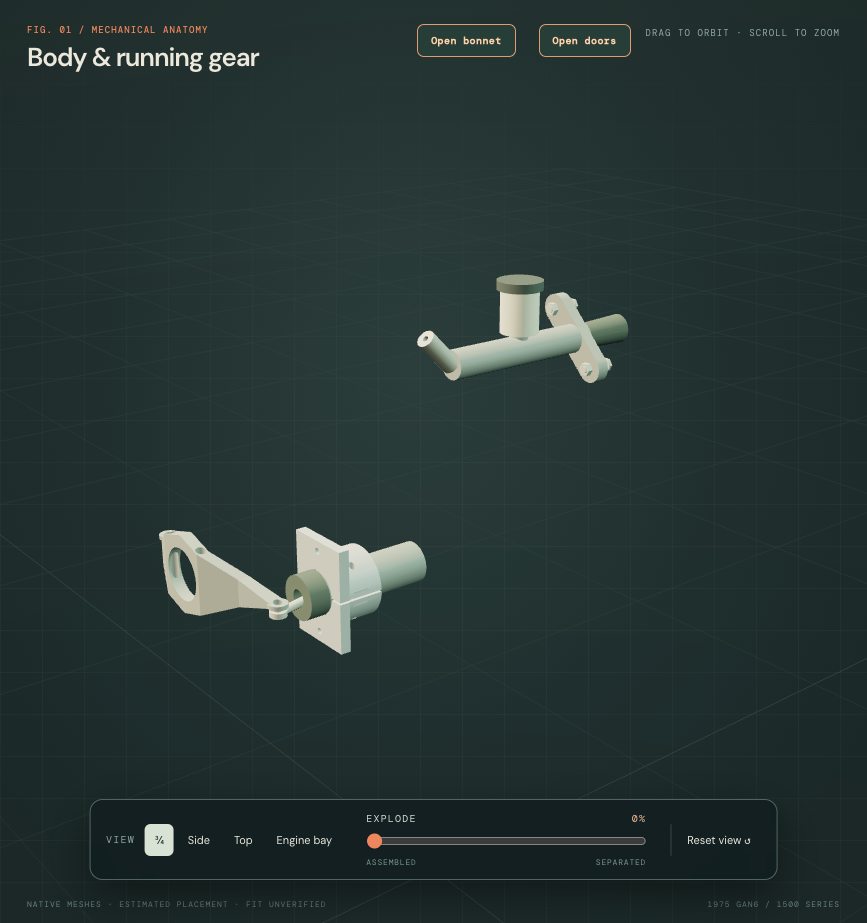
A hollow native pipe and two open union sleeves now connect the existing black-master outlet and slave inlet reference boundaries. Factory plate 156 lists BHA5375 for LHD1500 separately from RHD BHA5376 and earlier pipe lengths. It supplies the connection role, not this curve or its dimensions. The earlier separate hose listing is not transferred to this comparison.
The black-master pairing remains provisional. The smooth curve, 8 mm outside diameter, 3.2 mm bore and union sections are selected estimates. Neither end moves to force a fit. This is not a traced fitted pipe, a purchasing specification, a sealed hydraulic joint or proof of clearance. Internal master passages remain absent.
Before · separate outlet boundaries
After · estimated connecting curve
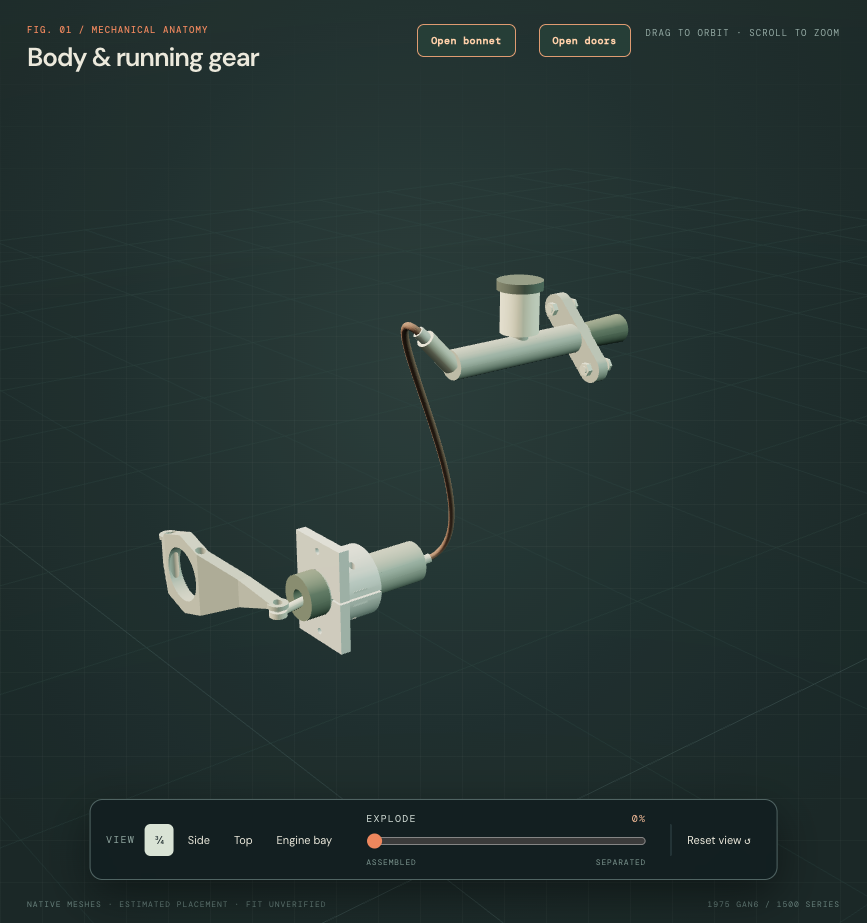
The selected curve intersects the retained bulkhead and left footwell reference panels: 152.93759 and 92.58737 mm³ of source overlap. The matched diagnostic views hide surrounding body panels to expose the connection. These are reconstruction conflicts, not fitted interference findings or evidence of an actual opening. No panel was cut and no route was moved to erase them.
Inspect the conditional pipe in the whole-car model ↗ · Read the scoped geometry checks ↗
The year does not identify the seal kit
The factory parts plate and the later supplier catalogue make different statements about clutch-master changes. The factory records market-specific cylinder and pushrod listings; Moss describes an approximate internal change and later service replacements. These are not established as one common change point.
| Source | What it records | Limit |
|---|---|---|
| Factory plate 107-G6 | AAU2298 cylinder and AAU3469 pushrod listings from GAN6-167343 for North America; GAN6-169644 elsewhere. | The plate does not decode these changes as a cup/ring seal identifier. |
| Moss issue 25, printed 139 | Approximate internal change around GAN6-169643, with later service cylinders also replacing earlier ones. | A car’s date cannot identify its present cylinder after replacement. |
| Moss kit list | Plain body, no circle/groove: AAU2298 family and GRK3005. Circle/groove body: GMC1005 family and GRK3008. | These are catalogue comparisons, not selection of a kit for the photographed car. |
The same Moss page excludes North American coverage from its 1500 slave/pipe subsection. That routing and its pipe applicability are not transferred here. The factory overhaul drawing SNC045 shows main and secondary cup roles; it does not establish the internals of an unidentified or later replacement cylinder.
The model’s pale/black labels describe photo envelopes. Its open rear pockets are construction clearances, not hydraulic bores. Neither cap color nor the explode slider establishes the fitted seal architecture, bore, wear, fluid compatibility or pressure integrity. No hydraulic internals, casting marks or repair-kit identity have been invented.
Read the factory cylinder and pushrod listings ↗ · Read the supplier’s variant note and scope ↗ · Reading record, source hashes and unresolved identities ↗
The existing factory dependency map below remains a comparison. A fitted-cylinder overhaul, disconnection or bleeding procedure is not verified by these model envelopes.
Factory procedures and modeled boundaries
The accessible AKM4071/B clutch pages 133–136, incorporating AKM3267, have been visually read; page 137 is blank. They connect these studies:
- 33.20.01 master: cover with coil, clevis, pipe union and mounting roles; cover/coil grouping already modeled.
- 33.35.01/.07 slave: inlet, locating groove/bolt, rod alignment and internal service roles; inspect the existing release assembly.
- 33.30.02 pedal: the U.S.A. procedure on page 135 differs from the U.K. version. Brake connections, switch wiring and optional counter add dependencies.
- 33.10.01 and 33.25.12: clutch/gearbox dependency and bearing/carrier pressing roles; gearbox study. Full gearbox-removal operation 37.20.01 remains unread.
- 33.15.01: bleeding is on page 133. The model does not verify fluid identity, pressure continuity or readiness for this procedure. Brake bleeding 70.25.02 remains unread.
These are documentary connections, not a complete actual-car replacement sequence. Display movement remains illustrative; loaded joints, access, press fits and removal paths are unverified.
What the open shapes mean
Reservoirs and caps
Estimated 2 mm tank walls/bottoms and open cap skirts expose container interfaces. No vent, diaphragm, cap seal, feed port, fluid compatibility or calibrated capacity is reconstructed. The photo-estimated outside sections supersede the earlier coarse envelopes; axis stations remain estimates.
Rear pocket and boot
The 12 mm-radius blind rear pocket and 8 mm-radius boot passage are construction cavities for viewing the rod boundary. They are not the hydraulic cylinder bore or evidence of piston, spring, seal or compensation-port geometry.
The open 3 mm-radius adapter passages retain old catalog-network endpoint stations and stop at the exterior. Internal valve/fluid paths remain absent. The observed photograph does not prove two fitted ports or trace their remote destinations.
Workshop boundary
Inspect and isolate bodies, tanks, caps, boots, fastener envelopes and outlet roles separately. The original master-only checks against the box, cover and two pushrods were zero; the separate pipe report records its scoped neighbor checks; this limited construction result does not validate global installed clearance, rubber sealing or operating travel. The attachment gap and unseen body counterparts remain unresolved.
Display separation is illustrative. No safe pressure release, fluid choice, adjustment, bleeding, master identification, tool access, disconnection order or verified replacement/removal path is encoded. The pedal study retains its unverified springs/stops/free-play and travel boundaries.
Native files
Fifteen source meshes contain thirty valid STEP solids. Construction and viewer checks cover open mounting bores, rear pockets/boots, reservoir mouths, metric placement/picking, isolation, declared display movement, study/download links and mobile layout. They do not validate a fitted pressure system.