Inside the front wheel.
Separate the retention chain.
Connected stepped hubs and rotor hats now share explicit fixing bores with separate studs, nuts and rotor screws. Bearing/spacer/seal boundary references surround the retained spindle datums; washer, castellated nut, unbent pin and hollow grease cap are independently inspectable.
Left front corner
Right front corner
Separate the evidence classes
| Basis | Applied scope | Limit |
|---|---|---|
| Factory PDF p. 140 | Disc-wheel BTA1254 hub; separate GHB129/GHB128 bearing, 88G321 distance piece, GHS142 seal, 2A4003 washer, 51K328 nut and 2A4067 cap roles. | Not identification of this car’s fitted hub, bearings, seal or nut. Wire-wheel references stay distinct. |
| NSK boundary dimensions | 7205 comparison 25 × 52 × 15 mm; 7203 comparison 17 × 40 × 12 mm. | Independent manufacturer sizes only, not a GHB129/GHB128 cross-reference, approved replacement, orientation/contact angle, race-face offset or preload specification. |
| Brembo 08.1509.10 | 209 mm diameter, 7.7 mm solid thickness, 60 mm total height, 64 mm centering and four holes. | Older steel-wheel application comparison, not fitted 1500 identification. No published wear or torque value is applied as a service instruction. Hat walls and 80 mm fixing PCD are estimates. |
| Owner/context and source datums | IMG_6329 wheel styling context; published axle frame and prior wheel/spindle/bearing stations retained. | No new owner dimension. Actual wheel/tyre markings, offset, hub/bearing identity and installed stack remain unverified. |
Construction changes and preserved datums
The connected hub keeps the old outside profile and wheel-flange station. Its inner seat shoulder moves from −35 to −37.5 mm and the outer seat starts at −3 rather than −6 mm: changes of −2.5 and +3 mm to meet the declared bearing boundary faces. These are drawing construction choices, not measured shoulder locations or a verified clamped bearing stack.
The inner/outer bearing centers remain −45/+3 mm, the estimated spacer remains 34.5 mm, the wheel mounting plane stays +20 mm, and the rotor center stays −44.15 mm relative to the nominal front wheel center. Boundary rings omit the races, balls, cage, face offsets and orientation required to evaluate a working bearing installation.
Keep the fixing patterns separate
Four wheel-stud/nut comparisons use the retained 101.6 mm supplier PCD and diagonal clocking. Four disc-to-hub bolt comparisons use the separate estimated 80 mm PCD and cardinal clocking. Rotor hat and hub flange share those four rotor bores; neither pattern is a fitted drilling template. Stud heads, nuts, knurls, threads, material grade, seating and clamp loads remain unverified.
Expose locking without prescribing adjustment
The supplier’s 51K328 castle-nut listing supports the slotted-nut role. New slots, an estimated 1.4 mm-radius spindle cross-bore at +17.5 mm, and an unbent pin envelope clarify retention. Their clocking and dimensions are construction references, not a fitted thread, drilling map, nut setting or verified bent/locked condition. Only two carrier meshes change; sixteen other kingpin-source meshes remain identical.
The separate cap retains its former hollow envelope. Its socket engagement, interference and grease sealing are unverified. Cap/retainer nonintersection validates limited static construction only. The newer formed-cover comparison has positive source contacts with the carrier; they do not establish fitted clearance or loaded seating.
No bearing orientation, face offset, fit, preload/end float, nut torque/locking sequence, lubrication, seal setting, actual wheel/rotor clearance, steering/suspension sweep, tool access or verified withdrawal path is established. Separation offsets are illustrative. The caliper study retains its independent casting and hose registration gaps.
Native files
Thirty source meshes contain fifty-two valid STEP solids. Checks cover shared wheel/rotor bores, reference-seat nonintersection and cap/retainer nonintersection. Viewer checks cover body-mm placement/picking, bores and stud/screw occupancy, spindle/castle cross-pin alignment, declared inspection movement/isolation, source counts, downloads/links and mobile layout. None certifies fitted bearings or brakes.
Disc retention and formed cover
The whole-car viewer now imports the revised thirty-part source. A stale twenty-six-part register previously rejected it and left coarse fallback hub geometry visible. Both front corners now expose the stepped hub, separate bearing and retention roles, revised rotor flange, formed dust cover and its small fixing.
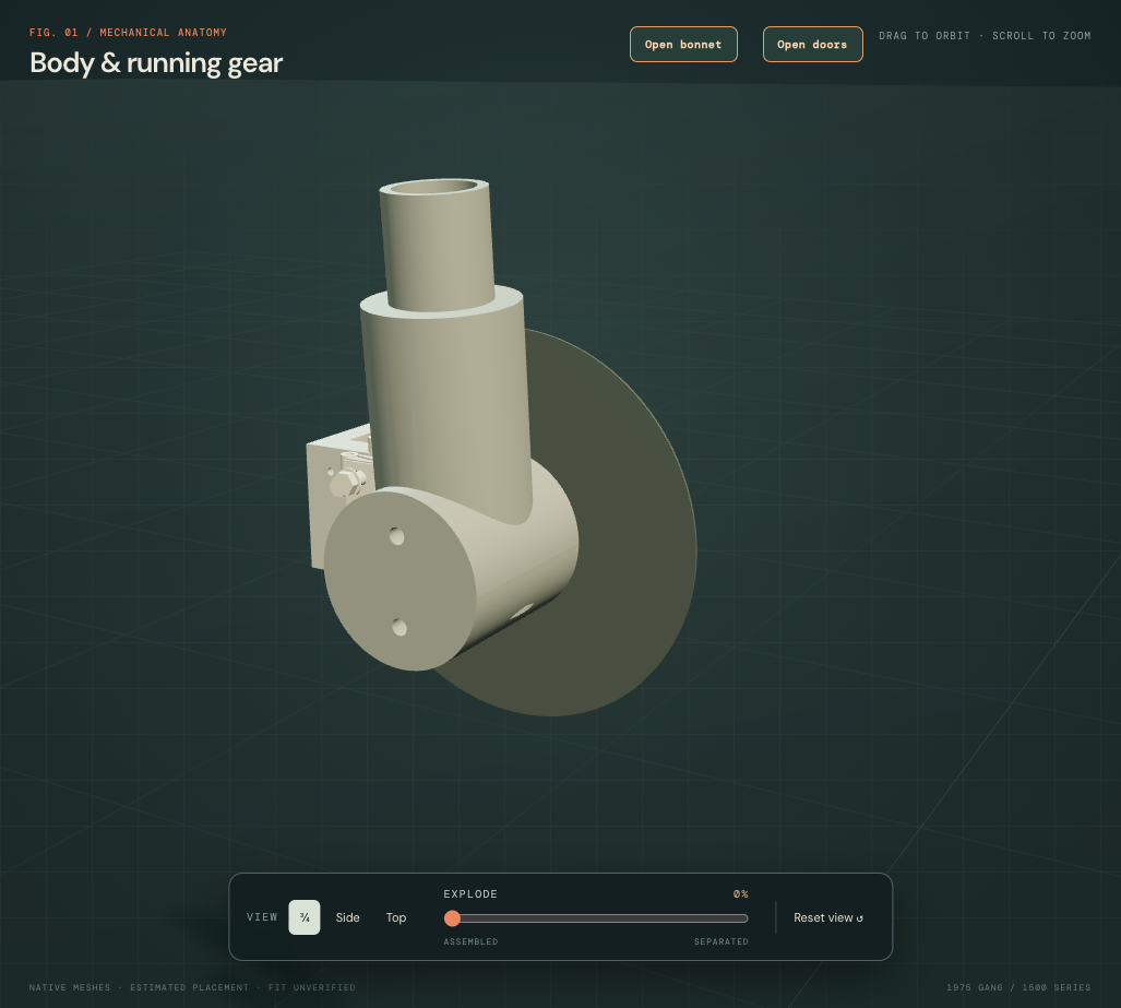
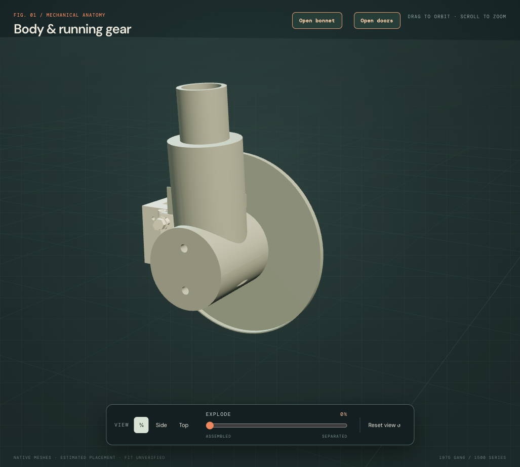
Factory parts plate p.142 distinguishes eight BTA370 disc bolts from the wheel studs and identifies handed BTA472/BTA473 covers, with two HZS503 small fixings and two LWZ505 washers per car. The modern BTA370 listing supplies a nominal 3/8 UNF × 11/16 inch comparison: 9.525 mm major diameter and 17.4625 mm under-head length. This replaces the former estimated 6 × 16 mm envelope; it does not identify the fitted bolts.
The four flange lobes and plain comparison bores now surround the retained fixing axes. Keeping the old under-head face at local X +8 mm places the nominal bolt tips at +25.4625 mm, beyond the existing +20 mm wheel face. That 5.4625 mm discrepancy remains explicit. Fitted bolt direction, receiver, thread engagement and hub/disc/wheel stack are unresolved; bolts are not shortened and the wheel is not moved to conceal it.
The formed C-cover adds an inboard rim return, two folded ears on the reference caliper mounting axes and one separate small fixing role. All sections, bends, stations and clamping layers are estimates. The small tab follows a tangent plane derived from the retained carrier footprint; this is not a surveyed mounting land. No receiver hole or spacer is invented. The modern SH605031 size comparison remains distinct from the factory HZS503 role, and cover presence on this car remains unverified.
Each cover still overlaps the source carrier by about 138.254 mm³. The nominal disc bolts overlap the wheel reference by about 838.51 mm³ per side. These are unregistered model discrepancies, not findings about the actual car. Sampled cover-to-caliper, cover-to-hub, cover-to-rotor and cover-to-wheel contacts are zero, which does not establish operating clearance. No verified 1500 release procedure or removal path has been established. Hiding the wheel/body and translating parts are inspection illustrations.