The documented piston and replacement-pad boundaries now appear in the current comparison below. The retained estimated mounting map conflicts with them. This is not a functioning brake assembly; earlier mounting and exterior revisions are historical comparisons.
Open the caliper.
Inspect the retention roles.
Separate native caliper exteriors, opposed piston/seal envelopes, pads with single-tab backing comparisons, shims, springs/pins, mounting screws/lock tabs and bleeder/banjo roles replace the coarse caliper and pad groups on both sides. Rotor, hub, bearing and wheel stations remain unchanged.
The right-side references mirror the construction geometry. Mirroring is a drawing choice, not proof of fitted handed details.
Factory topology and owner evidence
Factory PDF p. 142 and p. 143 separate handed calipers, GBP108 pad set, four shims and split pins, two pad springs, four mounting screws and tab-locking hardware for the car. The supplier front-brake listing corroborates the opposed two-piston caliper architecture and separate service roles. No listed caliper, pad, piston or hardware has been identified as fitted.
Existing owner underside views provide wheel/suspension context rather than calibrated disassembled caliper, pad or hose-end measurements. No new direct owner dimensions are applied. All new sections, profiles, bores, pockets and fixing maps remain estimates.
What the original retention reconstruction exposed
| Relationship | Construction and limits |
|---|---|
| Caliper / upright | Two estimated 4.5 mm-radius caliper bores share the old ear/web endpoints with new bores in two upright carrier meshes. Sixteen other kingpin-source meshes remain identical. Mounting screws and flat two-hole lock-tab envelopes do not establish fitted thread, torque, locked bending, seating or support strength. Positive cast/web contacts remain. |
| Pistons / pads | Blind 18 mm-radius pockets, 17.5 mm-radius piston-cup and unloaded seal envelopes clarify opposed piston roles. These are construction dimensions, not a verified hydraulic bore, pressure/seal design or service fit. The caliper stays one exterior assembly; no bridge-bolt separation or overhaul sequence is encoded. |
| Pad retention | Estimated ears grow from the old pad backing envelopes and share new retaining bores with the caliper. A bridge window exposes the spring/pin region. Smooth split-pin stems/loops, shim and spring envelopes do not reconstruct installed bending or spring force. The opening is not a verified pad withdrawal path. |
| Rotor gap | The old 1 mm gap on each rotor face is retained for display. It is not running clearance, piston setting, adjustment or wear allowance. The original rotor dimensional comparison and hub/wheel datums are preserved. |
Keep hose variants separate
Factory p. 167 distinguishes GBH139/GBH157 hose branches at GAN6-162565, banjo bolt 11D5264/gasket 3H550, and locking hardware explicitly linked to earlier GBH111. This car’s fitted hose branch remains unselected. Caliper mounting lock tabs are distinct from hose-locking hardware.
The new banjo eye, hollow-bolt and uncompressed washer envelopes expose a catalog connection role. Their bore, thread, valve/flare seating and orientation are estimates. The eye center lies 5 mm inboard of the retained network endpoint; the existing hose route is not moved to manufacture a sealed join. No hidden fluid channel or complete pressure circuit is inferred from open local passages.
Historical carrier-contact report
| Source part / carrier, per side | Intersection |
|---|---|
| opposed caliper exterior blind pockets and mount bores swivel carrier | 4823.92 mm³ |
| flat two hole mounting lock tab comparison swivel carrier | 0.0015 mm³ |
| open bleed screw exterior comparison swivel carrier | 4.8395 mm³ |
| banjo eye and unassigned hollow bolt envelopes swivel carrier | 89.7472 mm³ |
| two uncompressed banjo washer envelopes swivel carrier | 4.0984 mm³ |
The same values are recorded independently for the mirrored right side. The 0.0015 mm³ tab contact is a numerical-scale source result, not a physical interference diagnosis. Larger casting and fitting contacts still prevent installed seating or access claims. These are reconstruction discrepancies, not evidence of damage or actual interference on the car.
Workshop boundary
Select, isolate and illustratively separate pad, retention, mounting and hose roles. Valid source solids and open bores do not establish pressure safety, loaded sealing/locking, tool access, hydraulic release or bleeding order, hose travel, steering/suspension sweep or verified replacement/removal paths. No brake service setting or operating motion is supplied.
Historical native files
Thirty source meshes contain fifty-six valid STEP solids. Construction checks cover mounting/retention bores and nonintersection of the rotor comparison with friction pads, shims, spring and retaining-pin envelopes. Viewer checks cover metric placement/picking, shared caliper/carrier and pad bores, fixing/pin occupancy, isolation, declared display movement, source counts, links/downloads and mobile layout. They do not certify fitted brakes.
Historical connected mounting-stack estimate
The carrier webs now end in rounded mounting pads behind the existing dust-cover ear comparison. Each caliper has a separate bolt head, shared flat tab, carrier pad, cover ear and caliper ear. The caliper body, joint axes, spindle and bearing stations stay. Both carriers are now single connected native solids.
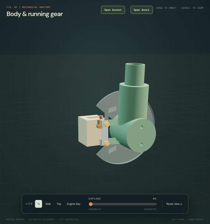
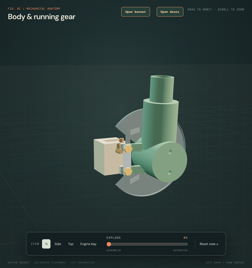
Factory p143 separates the BTA789 mounting bolts and shared BTC114 tab. The supplier BTA745 carrier view supports rounded mounting bosses; it does not measure or identify this car's casting. The BTA789 supplier listing supplies a 7/16 inch × 39 mm bolt comparison. Its length is interpreted under the head for this reference only. No fitted bolt or drilling size is established.
The 8 mm pad thickness, 9 mm boss radius, web profiles, 1.2 mm flat tab, head profile and 6 mm-radius plain bores remain construction estimates. The existing 1.5 mm cover-ear reference occupies its own layer; cover presence is unverified. Extra plain washers from the earlier construction are omitted in this tab-washer branch. The tab stays flat and unloaded: no actual bent locking state, thread engagement, clamp strength or torque is modeled.
Ten of 78 mesh groups change across the carrier, caliper and hub/cover sources; 68 stay identical. Native checks find the declared head/tab/pad/cover/ear surfaces touching, with no material overlap in that chain or against the held banjo and bleeder envelopes. The former carrier/caliper source overlap was approximately 4,823.916 mm³ per side. These are static reference checks, not actual-car clearance findings. The former cover/carrier overlap report also predates this single-solid carrier and layered joint.
The brake circuit remains unregistered. Factory p167 distinguishes hose variants and branch-specific hardware. Existing evidence does not select the fitted branch or a sealed route to the caliper. The hose endpoint, banjo reference and pressure passages are not moved or connected to manufacture a working circuit.
Workshop use: isolation explains which layers share the caliper mounting axes. It does not verify support, fastener access, hose release, bleeding, a caliper removal path or a safe replacement procedure.
Historical cast contours with undersized piston boundaries
The supplier's 17H9439 replacement photograph shows broad rounded cast forms, a raised circular piston-boss exterior and rounded mounting ears. The previous reference retained rectangular side slabs and sharp bridge/pad corners. The current comparison recesses the broad side webs, gives the retained circular bosses a shallow crown, and rounds the bridge and ear silhouettes. The supplier's RH replacement is not identified as this car's fitted caliper; the opposite side remains a mirrored construction estimate.
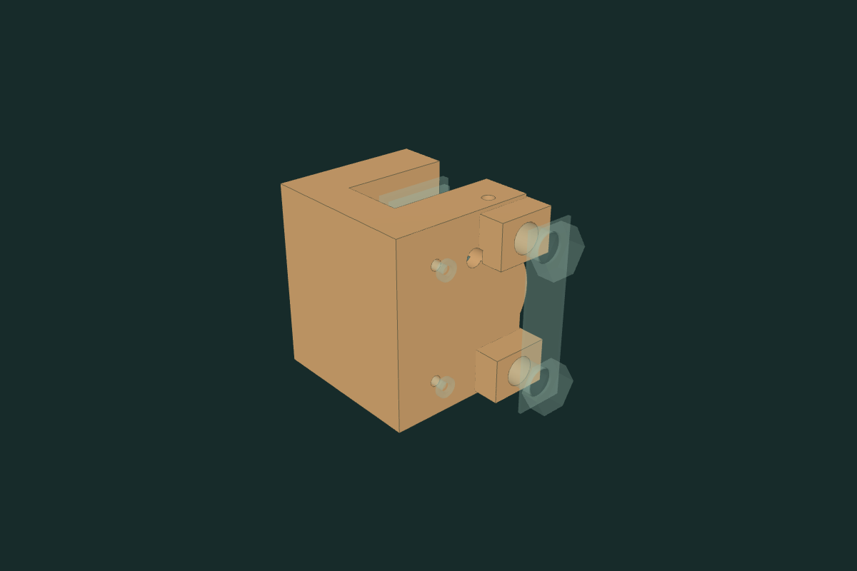
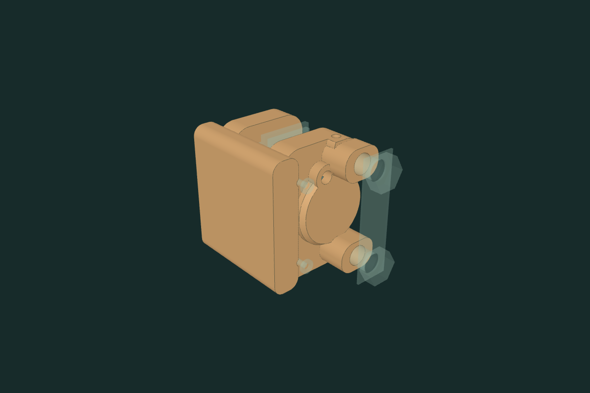
Side-web axial depth is an estimated 14 mm instead of 20 mm. The circular boss keeps its original inner radius and axis; its estimated exterior radius falls from 22 to 20 mm over the outer 6 mm. Side/bridge/ear silhouette radii are 12/6/8 mm, and the port/ear blends are estimated. These sections are unscaled construction choices, not factory dimensions, fitted wall gauges or a machining template.
Both complete body bounds remain within 0.000001 mm numerical difference. Piston and pad stations, mounting/retaining axes, axial joint faces, bridge window, inlet and bleeder maps, body/wheel/rotor/upright positions stay. The two changed bodies are single connected valid native solids; 28 other source mesh records and native volumes are retained. The full current export has 30 groups and 48 positive valid STEP solids. Earlier counts and mounting-stage reports above describe their historical stages.
Each body removes about 23,174.970 mm³ from the old construction with no added material. Mesh/native volume discrepancy is about 0.006140%. The validator compares 44 bounded static neighbor/internal pairs, including current carrier, hub, steering arm, pipe/hose and instantiated wheel/tyre references. Existing hose/union, pad-backing, bleeder and banjo source overlaps remain recorded. Reductions do not verify actual-car clearance or a sealed brake circuit; no neighbor moves or relief cuts are used to manufacture fit.
The revised geometry was inspected in the whole-car viewer and in matched native views. Browser checks cover all 30 meshes, metric placement, source selection, unavailable-source handling and a clean production reload. This is exterior reconstruction only: pressure passages, split-body joint, fitted casting identity, wall strength, seals, loaded motion, hose travel, hydraulic release/bleeding and verified removal remain unresolved. Display separation is illustrative.
A larger piston reveals the mounting problem.
The old model used 35mm piston cups inside 44mm bosses. Classic Motoring’s own 17H7960 listing specifies a two-inch (50.8mm) piston and two per caliper, with Sprite/Midget applications. Its photographs show an open cup and closed back. The new cups open toward the pads; the 28mm length, 44.8mm inside diameter and 3mm back remain photo-based construction estimates. Small rim notches are omitted.
Brembo P52002 supplies a 74×64×14mm replacement-pad boundary and photographs of a solid central tab without bored retention ears. Its early Midget application is family-comparison evidence, not identification or interchangeability for this 1975 car. The new outlines are estimated arcs, not traced factory contours. The modeled 10.5mm friction, 3mm backing and 0.5mm unloaded shim are estimated layers within the complete 14mm envelope.
Each mounting axis is only 28.16mm from the piston axis. The estimated 25.9mm-radius cavity and 6mm-radius mounting bore therefore overlap. Mounting screws also intersect the nominal piston cups. Native validity does not make these cavities sealed hydraulic bores. The surrounding carrier, cover, rotor, wheel, ports and hardware have not been moved to conceal the discrepancy.
New casting sections and unloaded seal envelopes follow the larger nominal boundary. The model retains the source piston centers, mounting/pin axes and external port stations. Individual pad layers move outward to accommodate their nominal thickness; the inherited 1mm rotor/pad display gap is unchanged. That gap and the 0.15mm piston/pad separation are drawing spacing, not operating clearances. Legacy native names containing “blind pockets” and “bored retention ears” remain solely to preserve existing links.
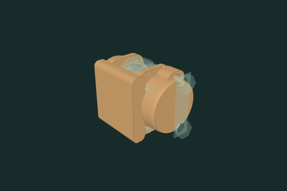
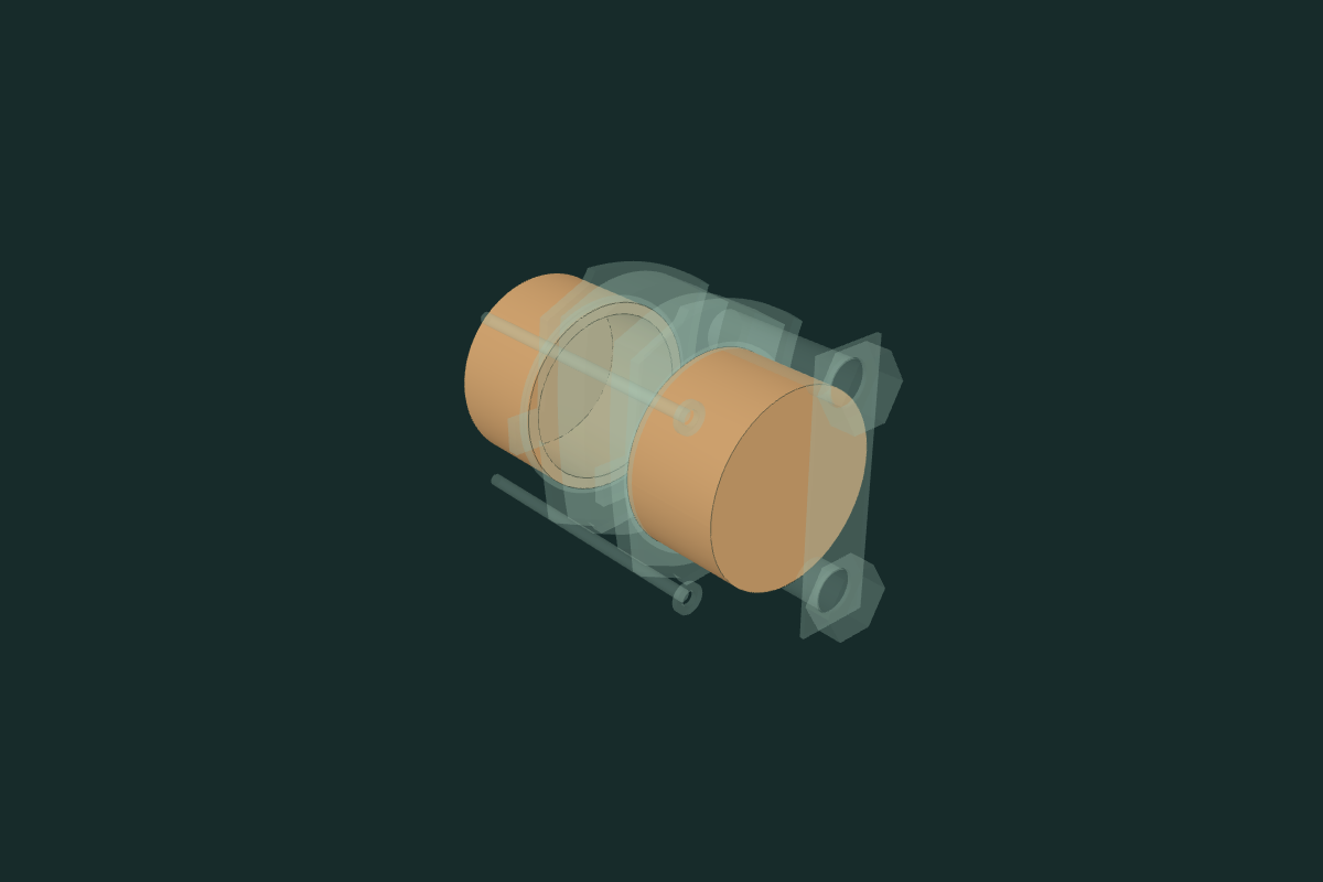
The conversion-bracket author’s mounting discussion reports 3.25-inch Midget centers. This is an unapplied lead: the drawing and original-car application still need checking before a coordinated carrier/cover/mount revision. Frenkit’s indexed piston height and section dimensions remain unapplied because the PDF request returned a verification page. No hydraulic circuit, pressure capacity, loaded clearance or verified service procedure is established.