Current revision: three-bolt damper / platform connection ↓
Follow the
kingpin.
The swivel axle now has a continuous bore around a separate kingpin, with two bush sections, lower dust tubes and a thrust washer. An offset upper trunnion connects to paired damper arms through its own bushes, pin and retainers. The old crossing solid cylinders are removed.
Two axes, distinct jobs
The earlier shared-front factory drawing separates the swivel pin, axle bushes, dust-excluder tubes, thrust washer and 2A4005 trunnion. Its damper drawing separates the 2A4028 horizontal pin, four upper bushes per car and arm-clamp screw. These supply component topology, not this car’s dimensions or a complete 1975 service procedure.
Rimmer’s own 2A4005 product photo and application listing show the offset orthogonal bores and include the Midget 1500. They do not identify this car’s trunnion. The construction places the horizontal axis 32 mm inboard of the retained kingpin line and 13 mm below its old top station along that line. The side, offset and height are estimates. The damper body stays at its prior stations; its arm ends move to this new comparison joint.
Source classes and limits
| Class | Applied or retained |
|---|---|
| Direct owner dimensions | None applied to these fitted joints. Available owner photos provide context without calibrated hidden sections. |
| Retained drawing datums | Kingpin line and approximately 37.25 mm shaft diameter, wheel/hub stations, stepped spindle sections, caliper-web endpoints. The old integral steering rods are now replaced by a separate lever/joint asset; its new lower eye height is explicitly estimated. |
| Supplier comparison | Y16 / 88G274 listing: tapered 23–29 mm OD and 12.7 mm bore. This is a Caterham replacement listing, not proof of a fitted Midget bush. Conflicting 16/17 mm axial readings are retained without application. |
| Estimated sections | Carrier bore, two 28 mm bushes, upper neck, dust tubes, 3 mm thrust washer, trunnion body/offset, upper bush half-length 20 mm with 3 mm lip, arm span and eye sections. An 8 mm-radius, 14 mm-long reduced kingpin terminal is added above the old shaft-top datum. |
| Nominal thread comparison | MGOC lists 3/8 UNF upper-pin nut and 5/16 arm-clamp screw. Nominal terminal diameters guide smooth envelopes only; no thread geometry or engagement is reconstructed. |
| Unknown | Actual shaft steps, reamed fits, wear, seals, lubrication drilling, shim stack, thrust end float, dust-spring 6K653, rubber compression and loaded geometry. |
The old shaft diameter is a coarse drawing value. The new matching sections do not validate it. Local open bores and nonintersecting pin/bush construction cannot establish running clearances, strength, steering travel, camber, caster or toe. The anti-roll attachment correction replaces the old horizontal pattern over the fork gap with a forward-wall plate. Its positions, sections and fitted relationships remain estimated.
Workshop use
Select the carrier, bushes, tubes, trunnion and retainers separately to study which components surround the kingpin. Their translations are inspection poses, without a verified release order or withdrawal path. The carrier, kingpin and some adjacent references share a display offset; that does not establish which pieces stay together during service.
MGOC catalogue p. 81 discusses reamed bushes, thrust shimming and suspension-unit removal. It is a supplier procedure, distinct from factory specifications and this car’s verified state. Its application, support conditions and surrounding connections have not been verified here. No shim combination, torque, spring-release instruction or safe removal path is applied to this model.
Native reference
Build the front-fulcrum reference first; this export reads its shaft axis and section. Validation covers valid STEP solids, local bores and pin/bush relationships, metric registration, retained spindle/web datums and independent viewer selection.
Separate steering lever, two-screw lock-tab mounting and tapered outer joint now replace the old carrier rod. Two blind carrier bores are construction references, not a fitted map or repair/drilling template.
Raised journals and a tapered upright
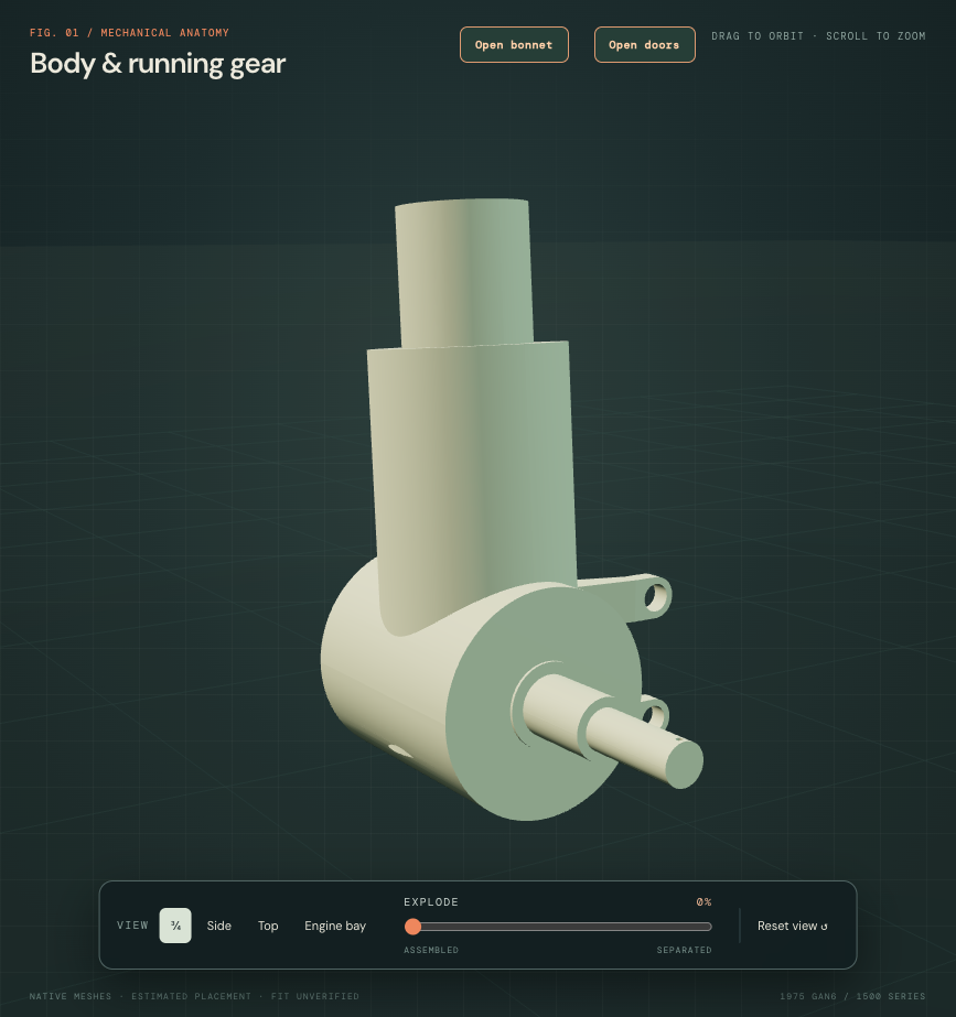
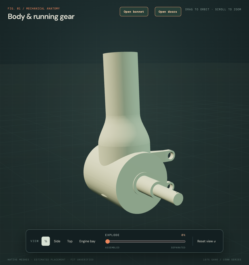
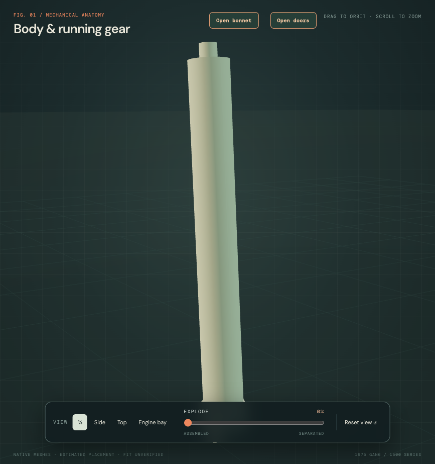
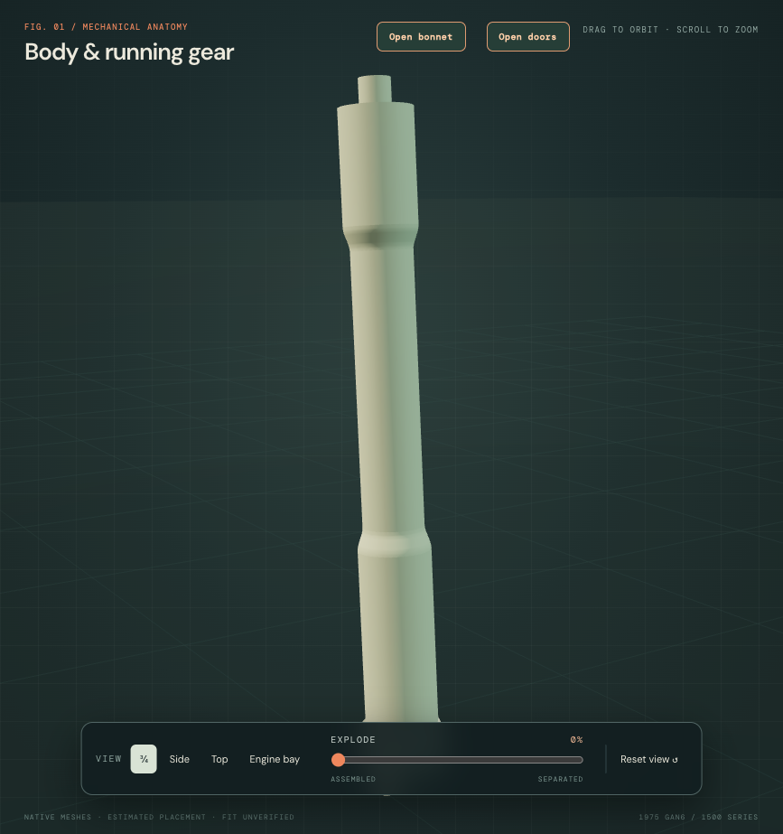
The constant-radius kingpin reference now has raised bearing bands and a relieved middle. The carrier’s long uniform upper barrel now blends smoothly into its existing narrow neck. This changes the major shaft and upright profiles without moving the wheel, kingpin axis, bush seats, spindle, steering arm or caliper mounts.
Inspect the upright ↗ · Inspect the kingpin ↗
The factory plate, PDF p140, and MGOC’s own kit photograph support stepped journal architecture. A H Spares’ assembly photograph supports a tapered forged upright. Neither image provides fitted-car dimensions or authenticates the installed parts.
The retained journal diameter is about 37.25 mm, and the complete height remains an early drawing estimate. This pass does not turn those values into factory specifications. The 3 mm radial relief, 12 mm shoulders and 155–200 mm carrier taper interval are selected reference geometry. Journal and bush-seat diameters, the lower foot, upper terminal, mounting holes and all component positions stay.
The changes remove material only. They do not establish bushing fits, lubrication passages, reaming sizes, end float, loaded strength, articulation or alignment. No new applicable factory swivel-pin removal procedure was accessed; inspection separation does not verify a release order or extraction path.
Connect the lever damper to its frame platform
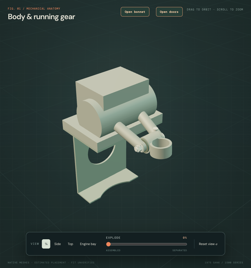
The previous damper combined three coarse body envelopes and round arm rods, without body bores or frame fixings. Each side now has a single hollow rounded body with three mounting ears, a separate smooth crossshaft/flat-arm comparison and three screw/plain-washer/spring-washer sets. Body bores share the existing platform’s estimated axes and lower bearing plane. Kingpin, trunnion, upper pin, clamp, arm-root and arm-tip stations stay.
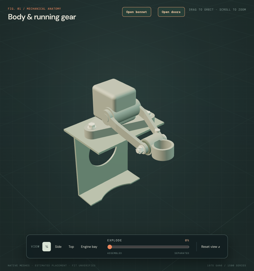
Factory parts141 / printed107-E26 identifiesGSA102RH/GSA103LH complete dampers and sixCHA398 frame bolts fromGAN6-154101, plus sixWA110061 plain washers and sixLWZ306 spring washers. This supports three mounting sets per side. Earlier53K1364 fixings remain a separate catalog branch. The plate supplies no dimensional hole map or fitted identity for your car.
RimmerGSA102P andGSA103P photographs support a compact rounded body, projecting shaft/arms and mounting ears. They do not calibrate the case, confirm a fitted new/rebuilt/uprated unit or establish working geometry. The retained paired-arm topology is a reference construction; its new flat sections and bent plan remain estimates. Left/right bodies use mirrored construction profiles, without a verified fitted handed contour.
The inherited three platform axes and baseY527.05..548.2167mm remain uncalibrated. The selected84×82×70mm body box,5mm hollow wall,18mm mounting-ear radius,22/10.4mm shaft-support outside/bore radii,10mm shaft radius,8mm arm thickness and35mm display screws are construction choices. The body’s empty cavity is not a reconstructed hydraulic system. Root eyes, shaft/bore spacing, arm sections and mounting holes do not establish loaded fits, spring load, damping, travel, alignment or strength.
Replacement connections are separate from a service sequence
The study now distinguishes the damper’s three frame attachments from its upper-fulcrum pin, bushes, clamp and retainers. These are connection roles for inspection. The exploded display does not prescribe dismantling the damper or releasing spring loads. The accessible factory plate is a parts diagram; applicable front-damper service pages have not been accessed in the available1500 workshop segments. No support/release order, torque, thread engagement, tool access or withdrawal path is verified on this car.
Native checks cover three shared bores per side, material around each bore, meeting body/platform reference faces and separate unloaded body/arm/fixing envelopes. Sixteen other kingpin meshes and neighboring suspension, hub, brake and steering source files stay unchanged. Those checks establish this static construction, not a working suspension or fitted-car clearance.