The missing
front connection.
The existing owner underside photos show a front anti-roll bar, frame clamp and link to the wishbone. That assembly was absent from the earlier whole-car model. Separate native bar, bearing/strap, stop, link, bracket and fixing comparisons now add the missing relationship.
Inspect the assembly
Presence is photo evidence; size is not
IMG_6914 shows the bent transverse bar, a frame clamp and a vertical link at the lower suspension. IMG_6919 adds the underside panel, rod and suspension context; IMG_6910 adds nearby structure. These supplied views establish visible presence and surroundings, but they do not calibrate bar diameter, bends, link length, rubber condition or attachment coordinates. The opposite side’s repeated pose is an unverified construction assumption.
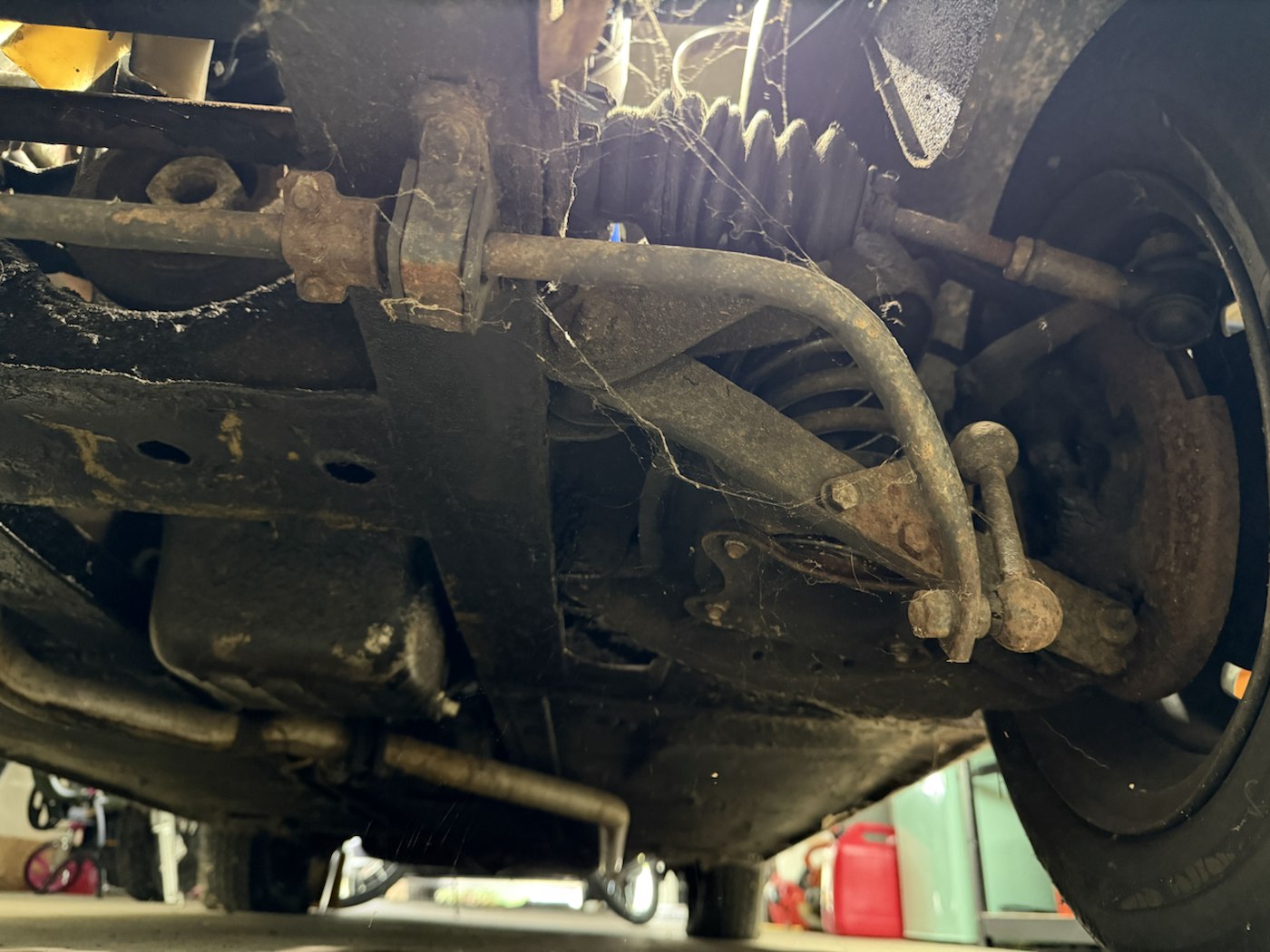
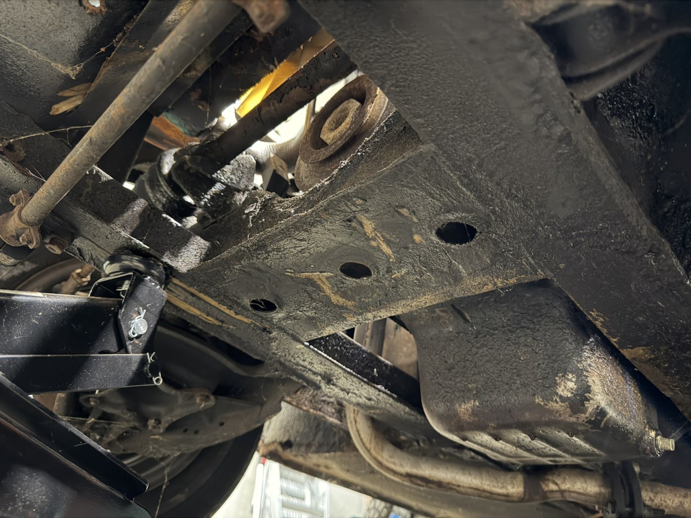
Factory PDF p. 144 separates AHA7013 bar, AHA7011/12 handed links, AHA7028 attachment brackets, AHH6541 bearings, 1B7356 straps and four stops. It lists four frame screws and six bracket-to-lower-link screws. Its optional/UK-standard application note does not identify this North American car’s original configuration. The owner photo, rather than calendar-year/catalog assumptions, is the basis for adding a fitted bar here.
The shaft uses the AHA7013 9/16-inch catalog comparison, equivalent to 14.2875 mm. This is not a measurement or identification of this car’s bar. The factory Special Tuning plate, PDF p. 317 keeps other bar sections distinct. No alternative diameter is selected from appearance.
Declared construction relationships
A solid shaft with tangent bends crosses beneath the estimated front rails. Two bored bearing envelopes and separate U-shaped straps face the frame underside; four split stop collars bound the bearing regions. Handed two-joint links connect end-eye references to upright wishbone bracket comparisons. The former horizontal fixing pattern over the outer fulcrum is superseded by the forward-wall construction below.
Correcting the attachment plane
Reinspection of IMG_6914 shows the flat plate on the wishbone’s forward-facing wall. The previous model put a horizontal base on top of the pan and an upright beside it. That placed one fixing in the outer-fork gap. The photo and factory plate topology support correcting that relationship, without calibrating its dimensions. Rimmer’s AHA7028 product photo separately shows a flat triangular plate with three small holes and a larger link hole; it does not identify this car’s bracket. Its generic “to body” application wording does not locate the bracket; the factory lower-link drawing and owner photo are the arrangement evidence.
The new plate follows the estimated front-edge tangent of the retained wishbone plan. Its three bores pass through the front wall, with material around them, rather than through the central joint opening. The wall extends downward to a declared 40 mm total depth over X magnitudes .43–.60 body units. The plate’s outline, 3 mm thickness, 0.4 mm display offset, hole pattern, wall depth and every installed coordinate are estimates. These values are neither owner measurements nor a drilling template. Inner pivots, outer fulcrum, spring opening and frame stations are retained.
The upper link stud points back through the plate; the lower stud faces forward through the bar eye. Ball, stud and bar-eye positions now share the declared front-wall normal instead of the old transverse X axis. The bent bar end stations follow those eyes. This corrects component topology while leaving articulation, contact, thread engagement, loaded offsets, drop-link handedness and suspension travel unverified.
Owner evidence supplies presence and visible attachment orientation. Earlier shared-front factory drawings supply parts and fixing counts. Supplier photos and nominal bar section are comparisons. All local metric geometry is estimated, including the repeated opposite side. Open modeled bores do not establish strength, running clearance, fitted alignment or compatibility.
Inspection is separate from replacement
General separation keeps frame straps fixed, translates bar/stops together, carries each wishbone bracket with its existing suspension display offset, and separates links/fixings for inspection. These offsets do not release an anti-roll load, articulate the joints or verify a removal direction. Factory exploded topology is not a complete safe lifting, unloading, loosening, refitting or tightening procedure; no such sequence or torque is supplied here.
What the dimensional audit established
The public source retains factory/cross-reference dimensions, photo estimates and provisional body stations as distinct classes. No filled owner measurement log was found in the reviewed repository files or MG download folders; that does not establish absence elsewhere or in browser storage, and already taken measurements need not be repeated. No photo estimate is promoted to a direct measurement.
The same evidence review reconciled the coil source metadata with IMG_7040: the clearer label reads 080 / 12 V / WITHOUT EXTERNAL RESISTOR / MADE IN MEXICO. It supersedes the earlier partial external-resistor wording. Actual wiring and electrical compatibility remain unverified; catalog GCL111/DLB102 comparisons and unchanged canister dimensions do not identify this coil.
Independent CAD export
Construction checks cover positive valid solids, STEP round-trip, six matching front-wall/plate passages with neighboring material, open link bores, native source scale and display grouping. Four frame-side source mesh records are unchanged. They do not certify actual dimensions, component condition, fit, loads or replacement access.