Across the
mounting gap.
A formed front-plate comparison now joins the central plate and mounting tabs as one reference part, beside separate frame brackets, rubber/metal faces and fixings. The original central plate geometry, engine/body pose, mount axes and bearing planes stay. Fitted mounting remains unverified.
Inspect the support boundaries
Evidence reconciled first
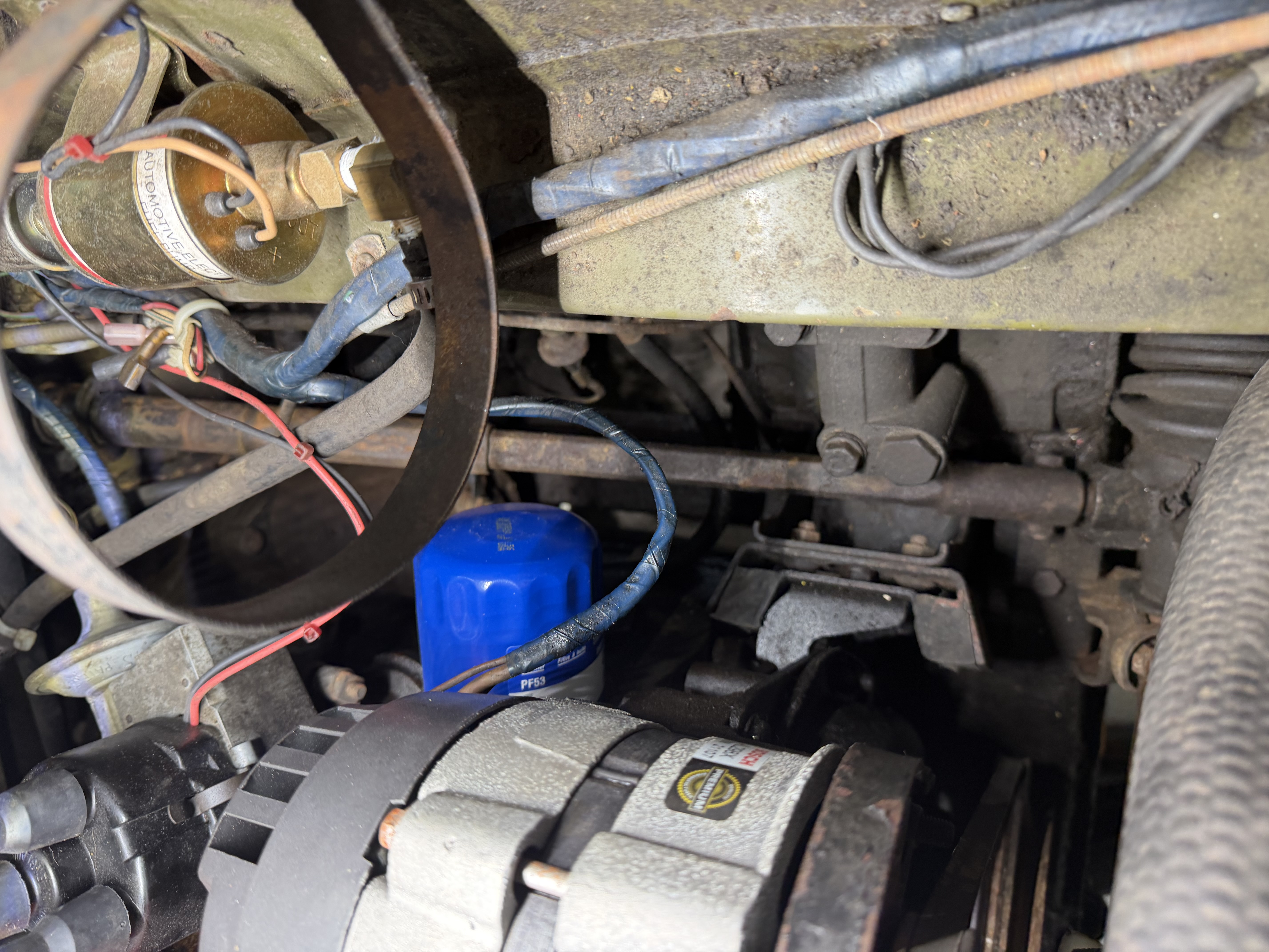
Owner IMG_7041 shows the filter-side plates, visible fasteners and rubber area beneath the alternator, beside the filter and cross-car shaft. IMG_6897 retains wider locating context. These views supply recognition and relative surroundings, not calibrated widths, opposite-side geometry or hidden attachment positions.
Factory mounting plate, PDF p. 72 separates CHA258 LH / CHA257 RH frame brackets, two front rubber supports, two bracket-side fixings and one engine-side fixing per mount, plus three frame screws per bracket. CHA280/CHA565 at GAN6-166304 remains a catalog branch, not fitted identity. Fastener quantities guide recognition only; displayed dimensions, pitch, threads and mounting map are estimates.
A formed front-plate comparison
Factory engine plate 61 distinguishes 215372 from the North American/Canadian TKC1830 front plate and shows formed tabs. IMG_7041 supports the filter-side mount profile, but neither source calibrates the complete shape or identifies this car’s fitted plate. The old central source plate remains geometrically intact; the former separate strips and thick feet are superseded by one connected plate reference with radiused folds.
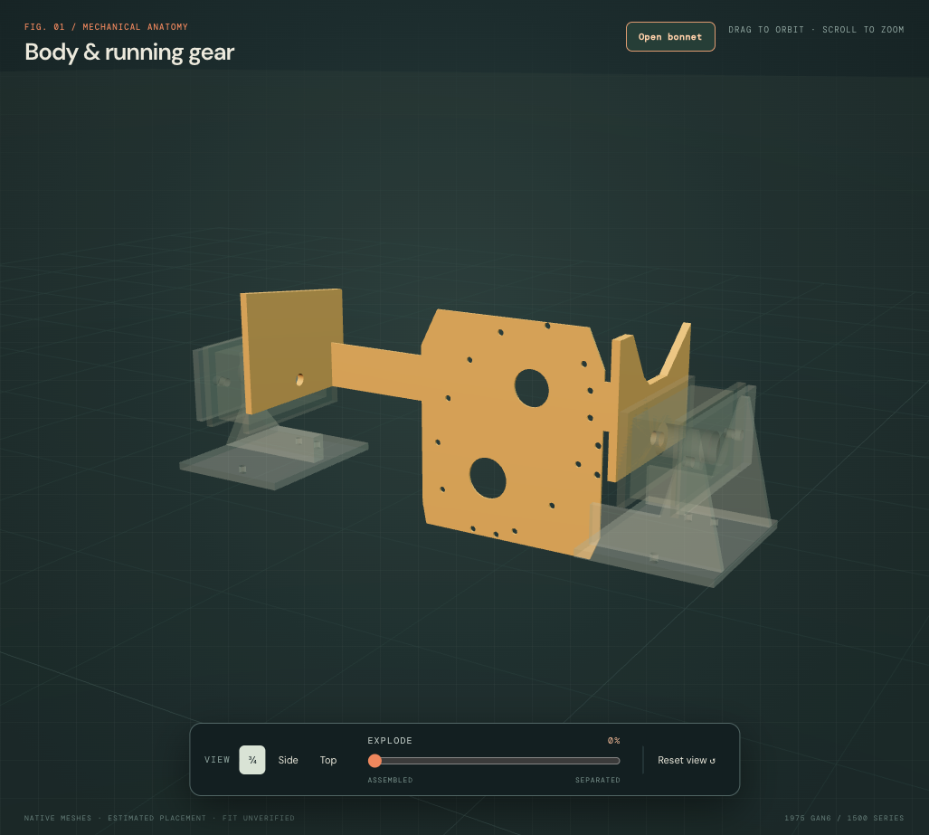
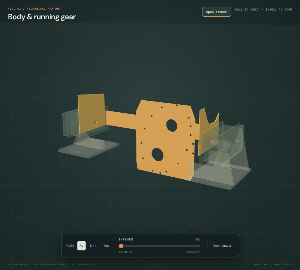
The old pieces already touched and could be mathematically fused. The improvement is the thinner sheet construction, rounded folds, trimmed rear tangent and single-part ownership. It does not newly prove an attachment or establish a fitted load path. The original mounting bore lines and outer bearing planes stay; the thinner tab middle planes move 3.58 mm outward under those held faces. The six bracket, rubber and fixing meshes are unchanged.
Registration conflicts remain visible
The mounting-extension source overlap with the steering shaft falls from 5351.207371 to 1038.907578 mm³, while left/right damper-platform overlaps fall from 4573.811641/7890.927254 to 1350.534933/2349.956710 mm³. Alternator-case and rotor-envelope overlaps remain 2592.786286 and 507.367214 mm³. These are source-model discrepancies under unregistered frames, not measured contact or clearance on the car. The body, engine and rack are not moved to erase them.
Base holes lie over the illustrative frame rail, but the rail remains unmodified: no fitted rail hole map is invented. Separate fixing envelopes expose bores for inspection; they do not establish bolt grade, thread, engagement or tightening values. Rubber free/loaded shape, compression, bonded construction and support forces remain unverified. The right profile is factory recognition, not a mirror survey of this car.
Keep procedures and display motion distinct
Workshop PDF p. 9, printed p. 82 is headed U.K. specification and separates front LH 12.45.01 from RH 12.45.03. The RH text includes exhaust-joint access. These establish documentary dependencies only; the existing mounting study keeps those reading notes separate from a complete applicable North American procedure.
In the general separation view, frame brackets stay fixed, the complete front plate shares the existing power-unit translation, rubber envelopes move outward, and fixings have an independent inspection offset. This is not mount release, a safe engine support state, lifting height, disassembly sequence or verified withdrawal path.
Rear support and North American branches remain open
The existing rear cradle and rubber pair retain their estimated pose. The gearbox-cover/bracket fixing map, case contact, tunnel/floor attachment, loaded rubber position and common body frame remain unresolved. The factory CHA463 restraint cable, CHA487 restraint, CHA488 rubber pair and UKC5254 RH front tie bar are separate comparisons; their presence and attachment on this actual car are unverified and are not added as fitted hardware. Do not infer them from the calendar year or use the current mesh for an order.
Independent native export
Checks cover seven source groups / 38 positive valid STEP solids, one connected plate, unchanged central plate geometry, six held bracket/rubber/fixing meshes, open mounting bores, retained bearing planes, native metric placement and a working fallback to the original engine plate when the support source is unavailable. They do not verify fitted joints, loads, operating clearances or a repair trajectory.
Central mount access restored
The previous rubber comparison filled its central region, and the outboard metal face had no access opening between its two stud positions. That blocked the engine-side fixing region even though the smaller inboard metal hole was open. The CHA565 product photograph and factory attachment layout support a central access region distinct from the two outer stud fixings.
Both reference mounts now have an open core and outboard-face passage, while retaining the smaller inboard fixing hole and its surrounding bearing material. The access diameter follows the model's existing frame relief; it is an estimate, not a factory dimension, socket size or measured clearance. Mount envelopes, poses, bracket geometry, fasteners and the engine/body registration remain unchanged.
This uses CHA565 as a topology comparison. It does not identify the fitted rubber or resolve the CHA280/CHA565 chassis change. Rubber internals, bonding, compression and the path for a hand or tool remain unverified. General separation is illustrative, not a mount-replacement procedure or an engine-support instruction.
Factory paired replacement rule ↗: 76-A-2 documents the CHA565 stop revision and paired interchange. The reference model does not simulate stop contact or travel.