Find the coil.
Trace the circuit.
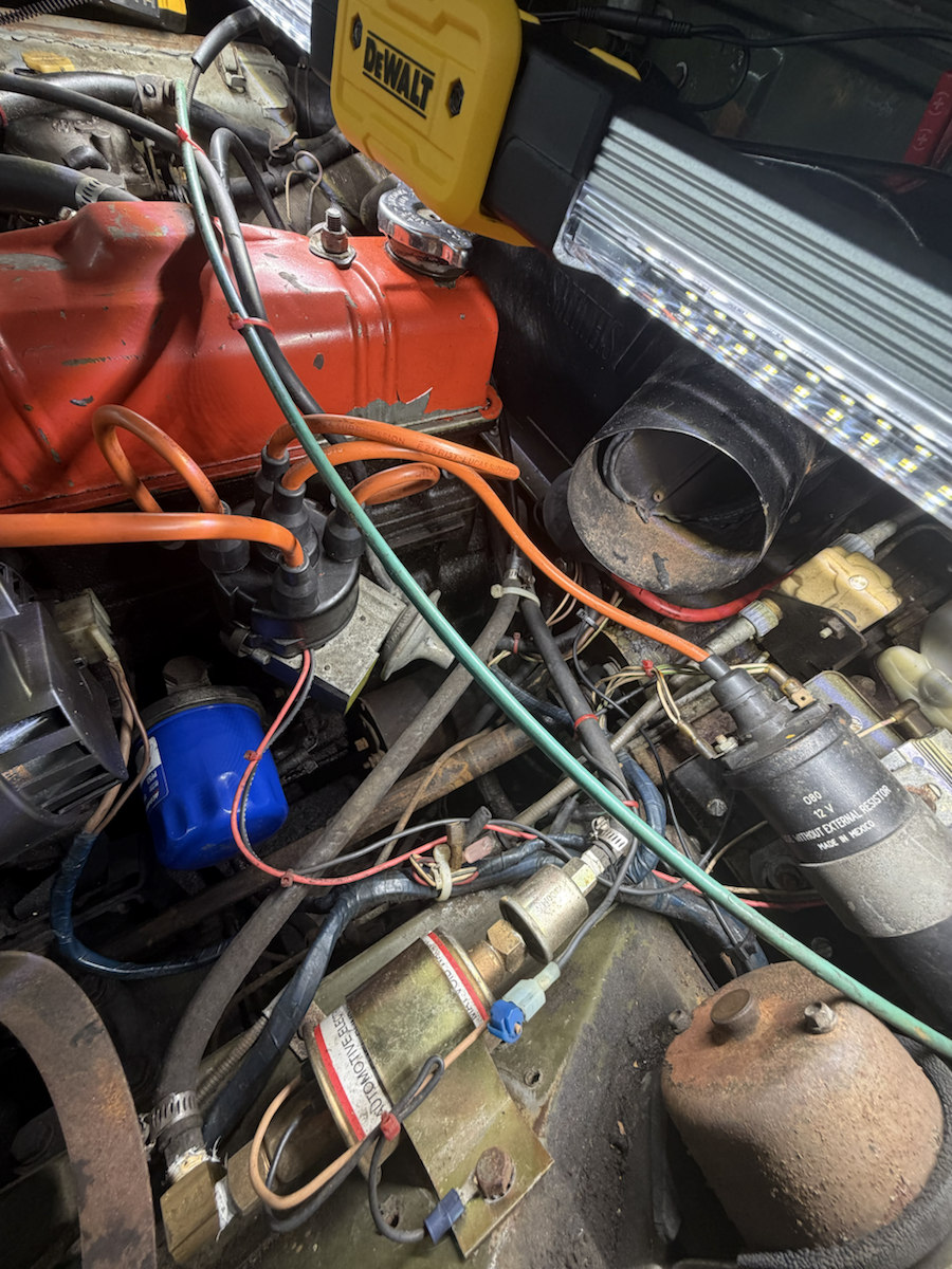
IMG_6973 shows a black ignition coil beside the distributor, with a warning to use an external resistor. The CAD now includes its canister, strap, terminal end, two mounting cues and a center lead. Their exact dimensions, position and wiring still need direct checking on your car.
Original catalog group
The 1977 factory Midget parts book, PDF p. 175 lists GCL111 as the Midget 1500 North American ballast coil. It lists a separate 13H9440 resistor for the electronic ignition driver and two HZS405 coil-to-body-bracket screws with plain and spring washers and nuts. These are catalog references; none identifies the actual can in the photo.
Size used by CAD
A Lucas DLB102 replacement listing gives a 50 mm body diameter, 105 mm body length and 150 mm overall height. The CAD uses that can size as a comparison, with estimated cap, bracket and body-side station. DLB102 is not a verified part number for this car.
What to document on the real car
- With ignition off, photograph every side of the can, then transcribe its maker and part number only where the characters are clear. Record the “external resistor” warning separately.
- Photograph the cap and label each low-tension wire by the actual terminal mark and wire color before moving anything. Trace the center high-tension lead all the way to the distributor; the black CAD cable is an illustrative route.
- Locate and identify any separate resistor or resistance wire by following the applicable 1975 North American circuit diagram. The catalog’s 13H9440 item does not prove that component is fitted here.
- Measure the metal can diameter and straight body length directly, excluding the strap, rolled edges and terminal tower. Record both values in the coil inspector; a separate owner STEP can use them.
- Photograph the complete bracket and both mounting fixings. Record their real center spacing and access direction. The virtual screw positions cannot establish a withdrawal path.
- If diagnosing or replacing the coil, use the complete applicable workshop procedure to check primary resistance, ballast arrangement and terminal compatibility. A “12V” marking alone does not settle those questions.
The coil is body-mounted in the virtual assembly, and the center lead joins the distributor cap. Its visible connection is useful for orientation. The CAD does not simulate the ignition circuit, establish wire polarity or prove the fitted coil’s resistance, bracket or dimensions.