This archive includes earlier web-size owner photographs and the newly supplied IMG_7034–7042 JPEGs for the 1975 Midget. Open any image for a larger view. The photo locator marks the clearest assemblies and links them to workshop jobs. Earlier HEIC originals remain in the owner's folders; their copies were rendered for browser use. IMG_7034–7042 are linked as supplied JPEGs.
New owner batch · IMG_7034–7042
Nine newly supplied views cover the carburetor, intake, filter, distributor, coil, mount area and exhaust-side pipe joint. IMG_7036 is soft; the other angles add clearer detail. All views remain uncalibrated.
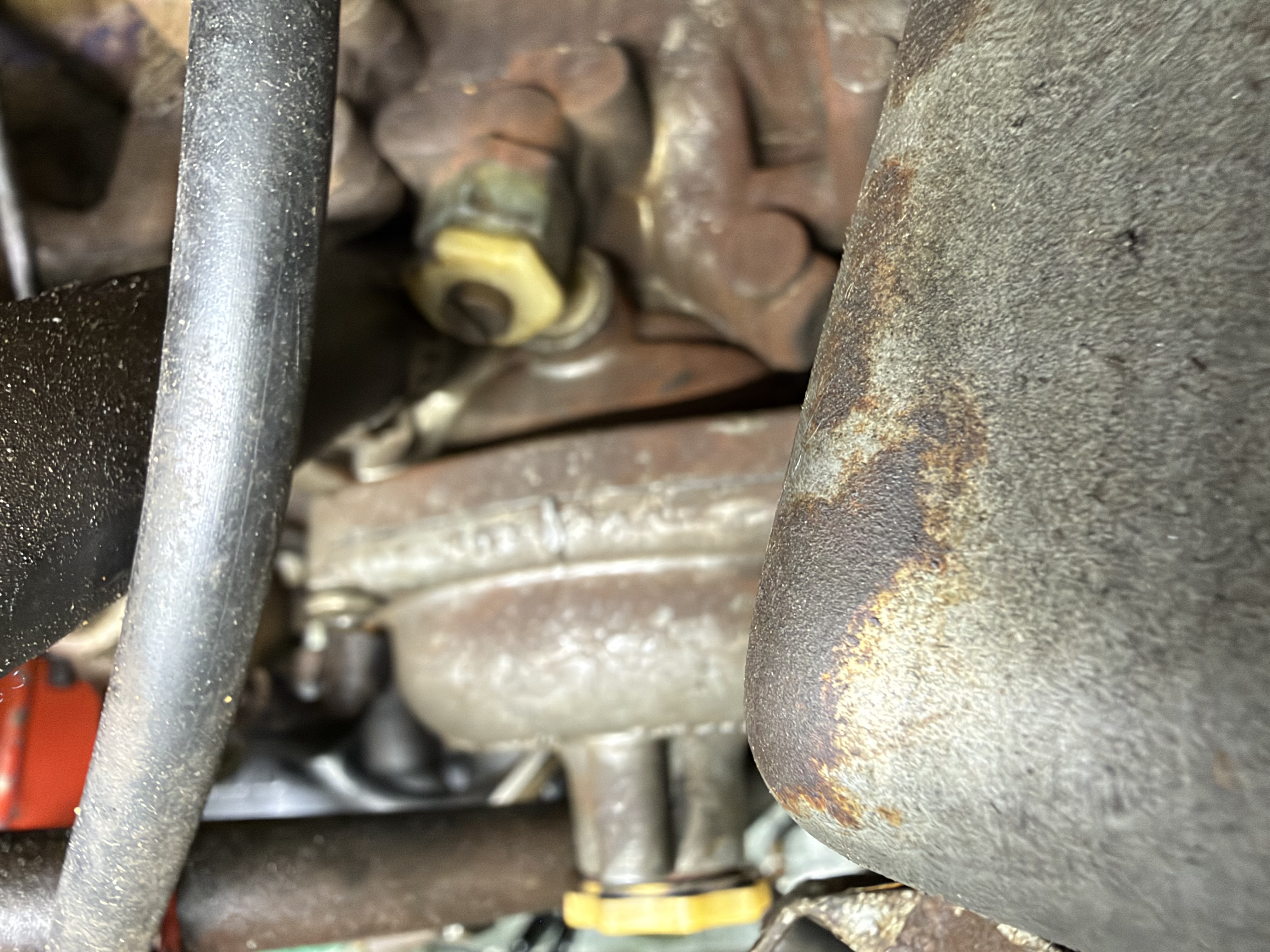
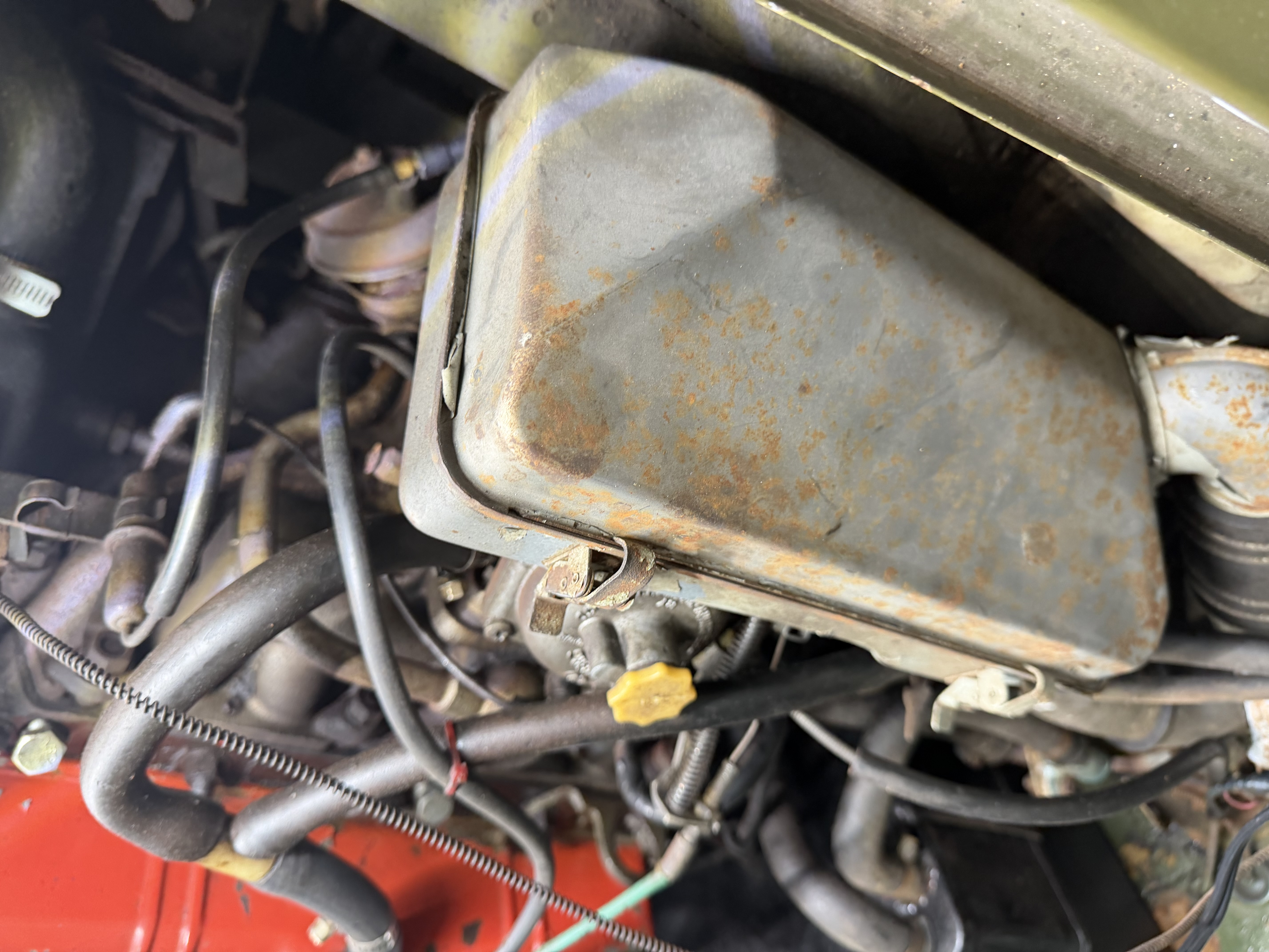
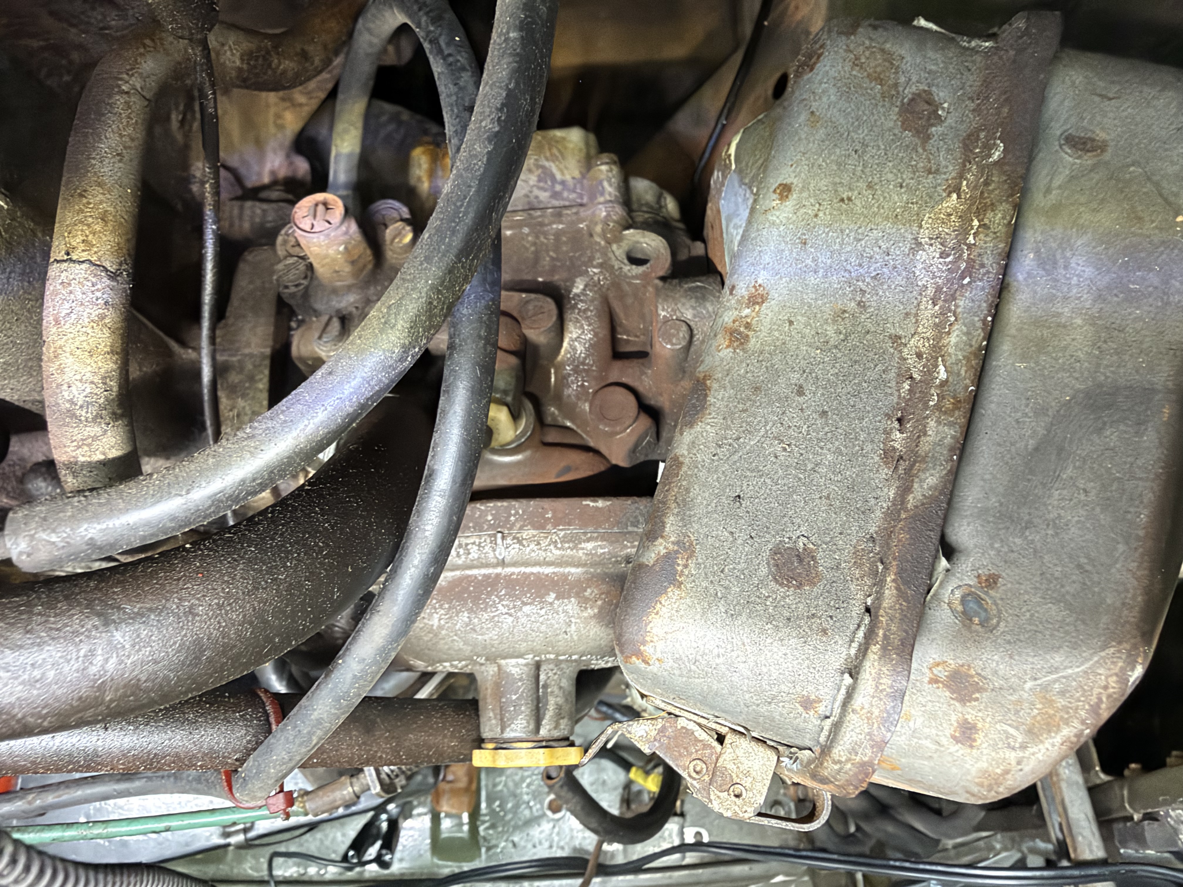
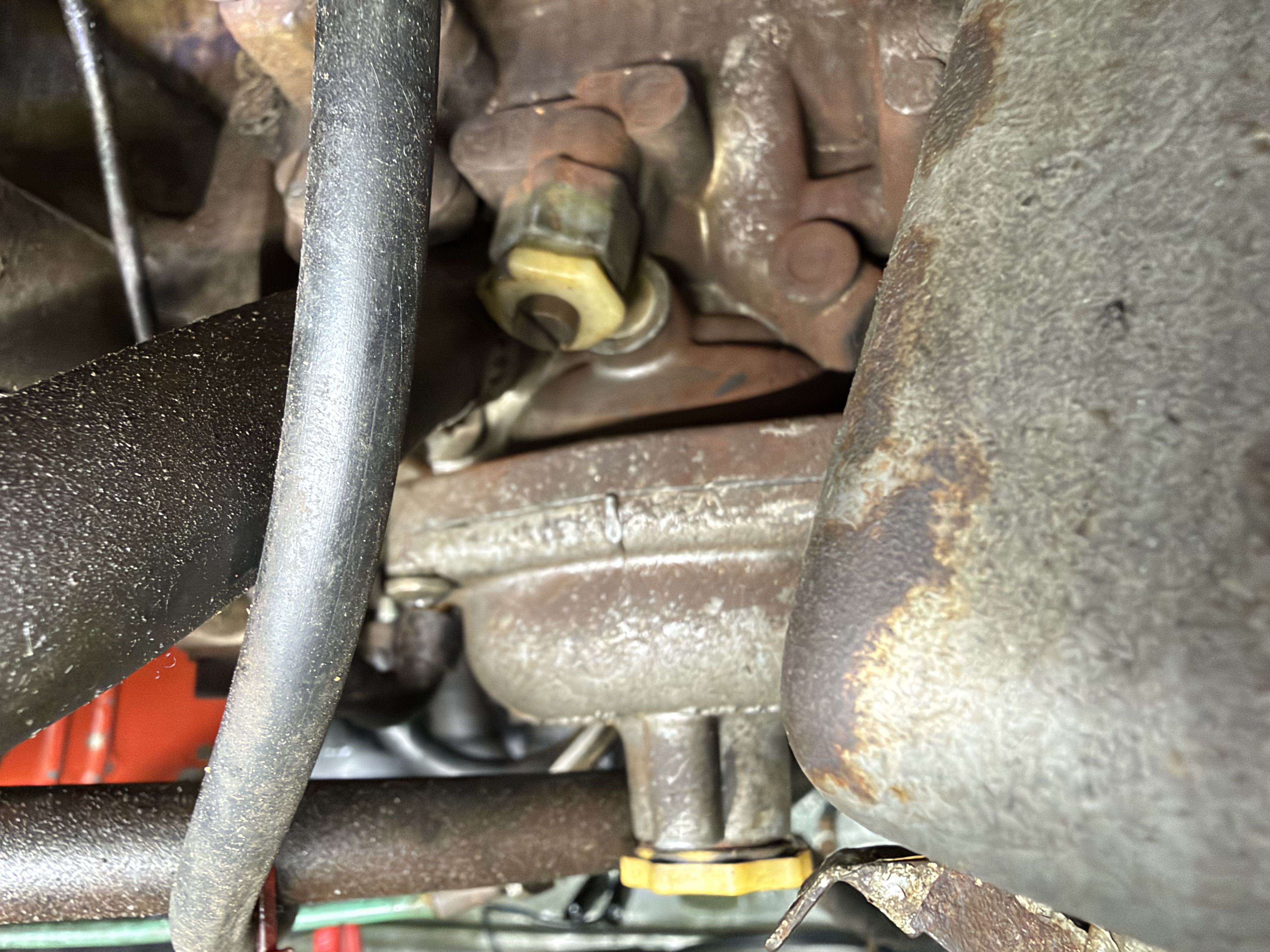
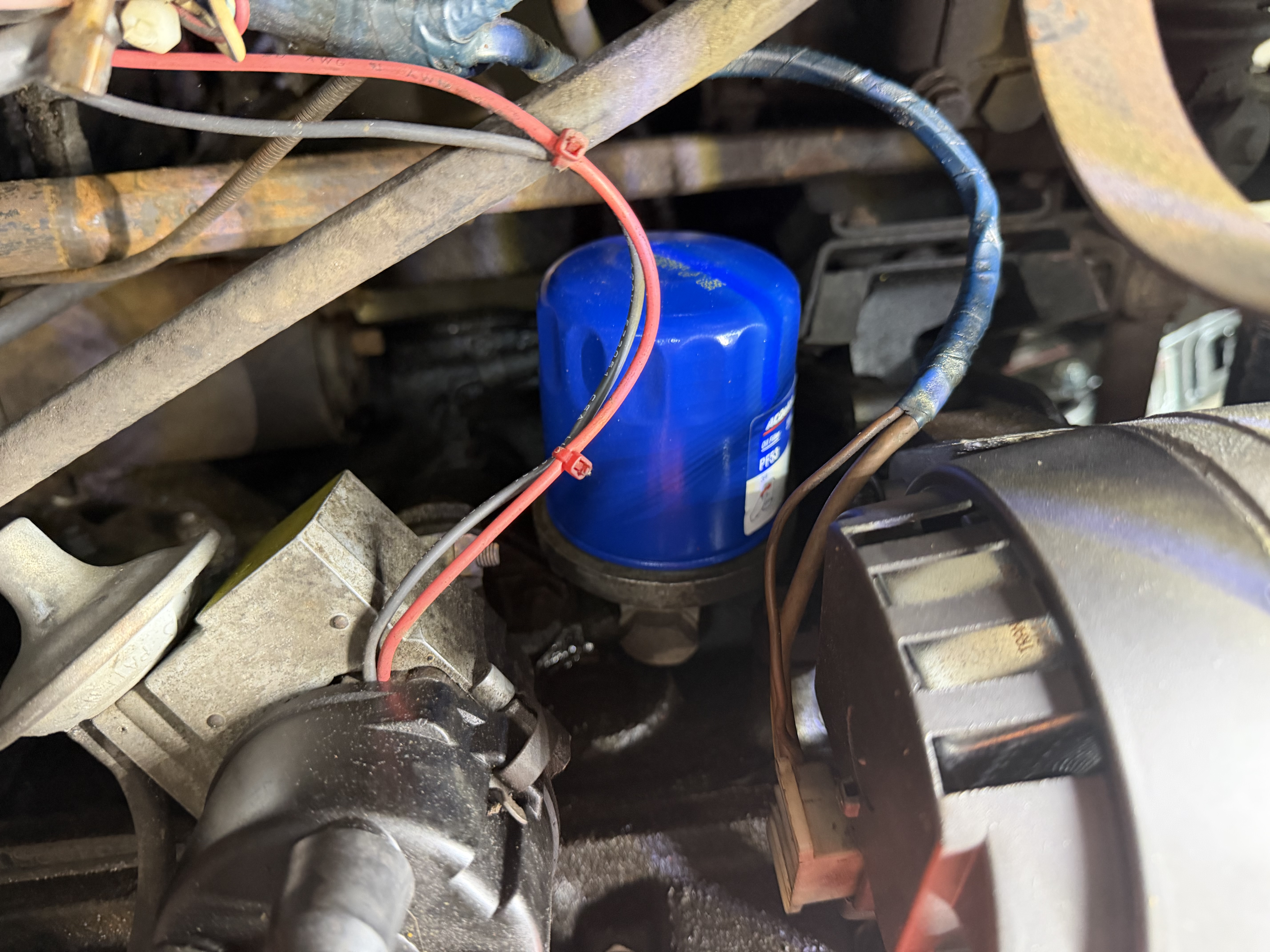
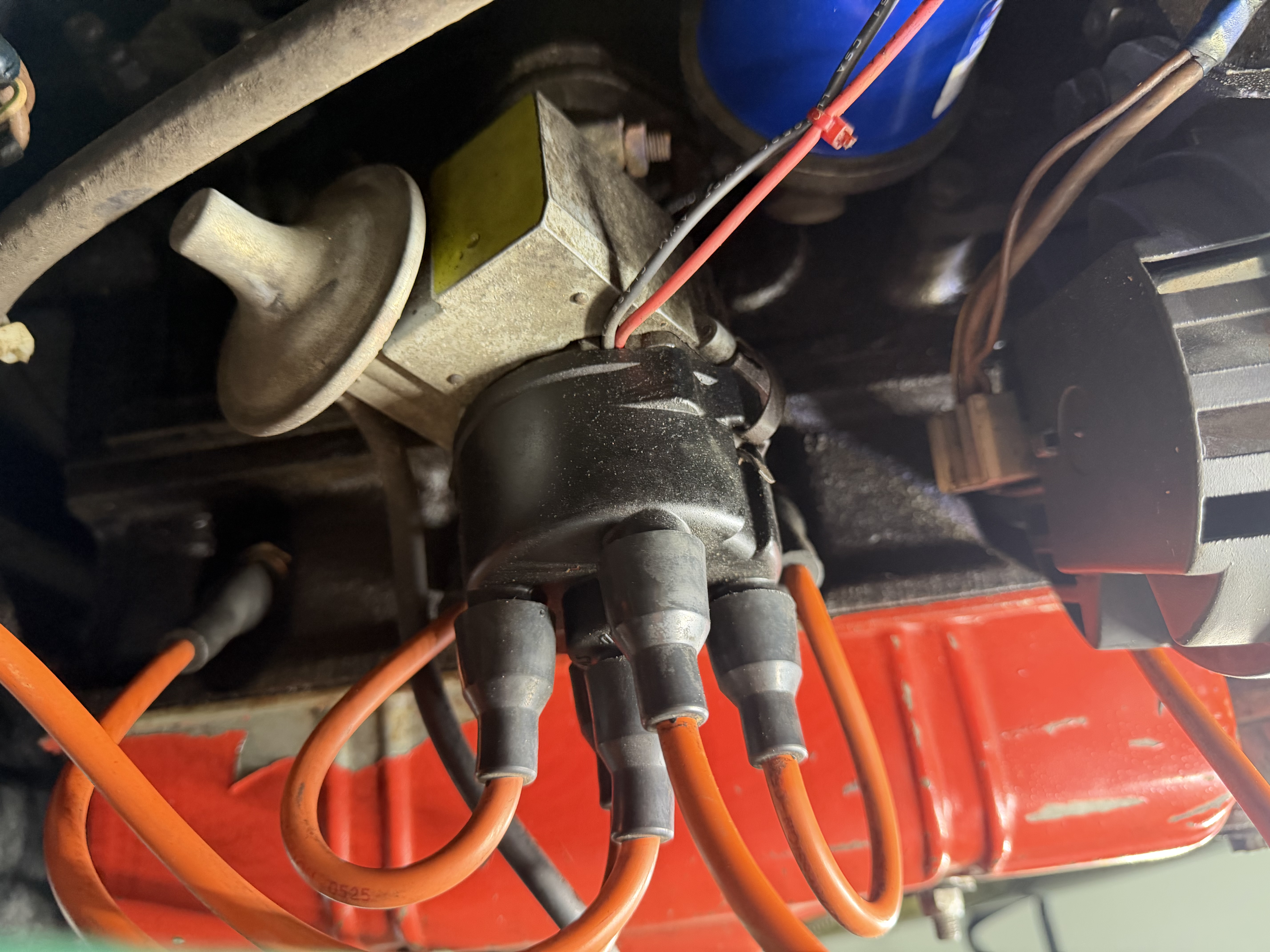
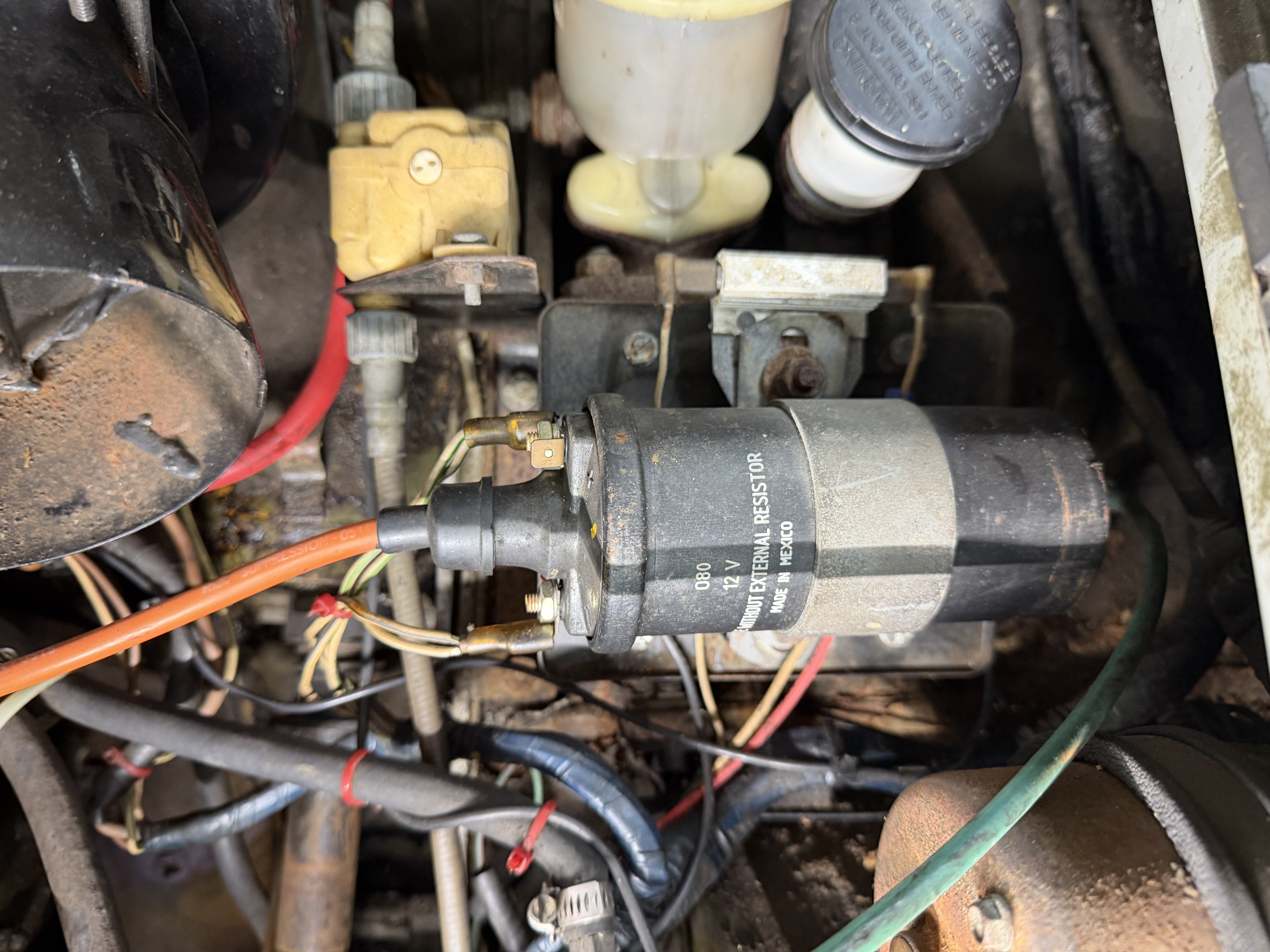
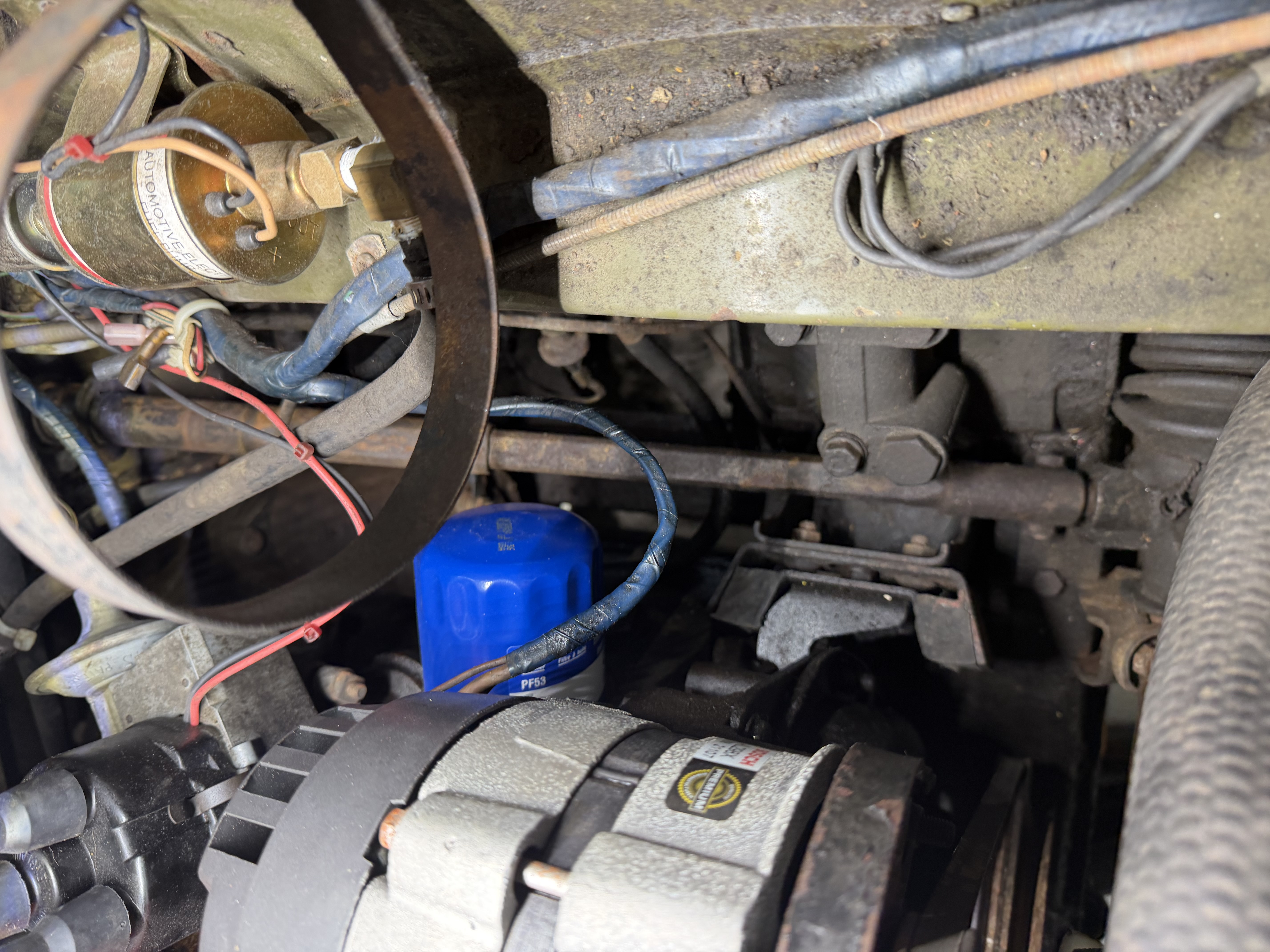
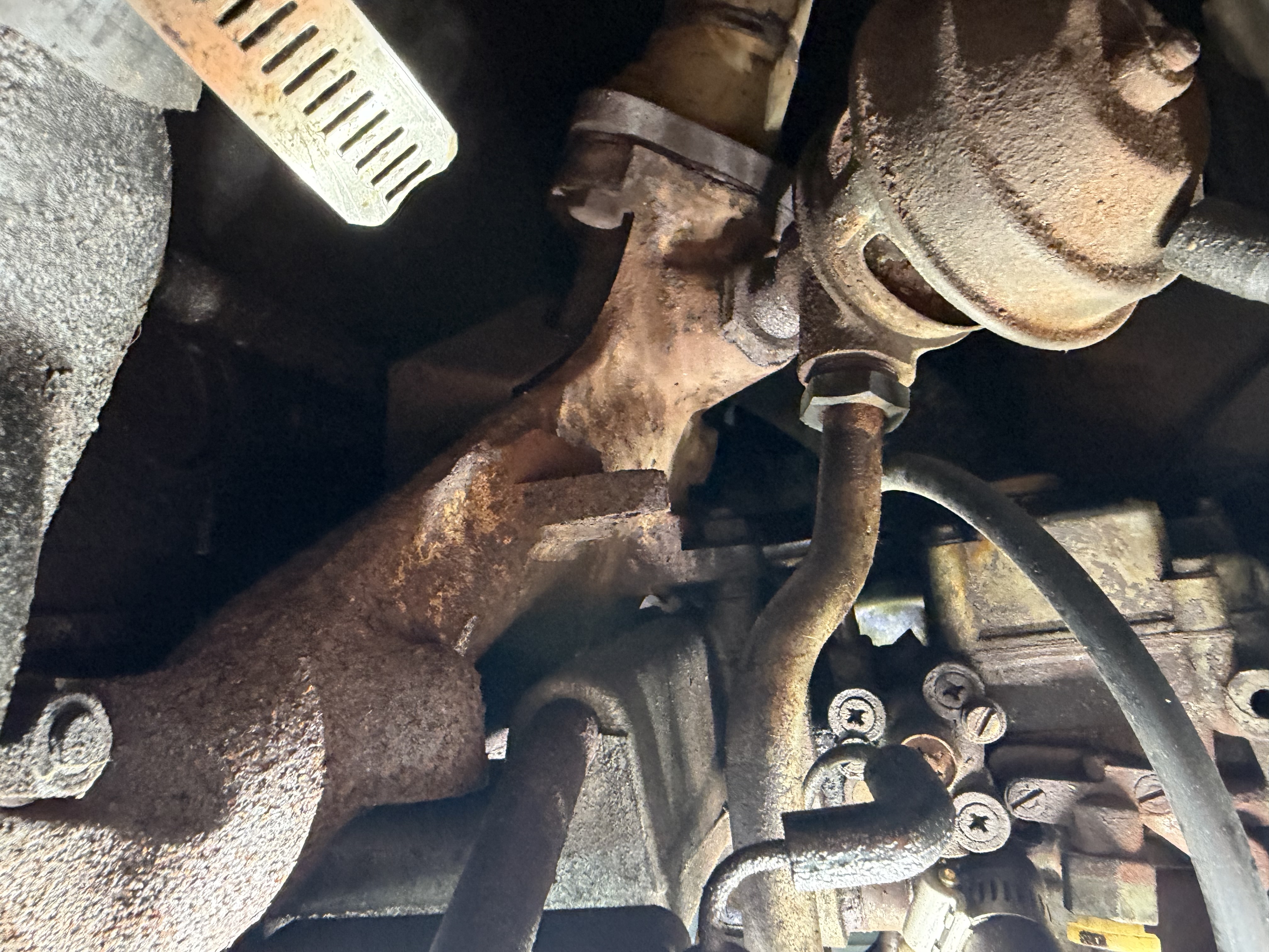
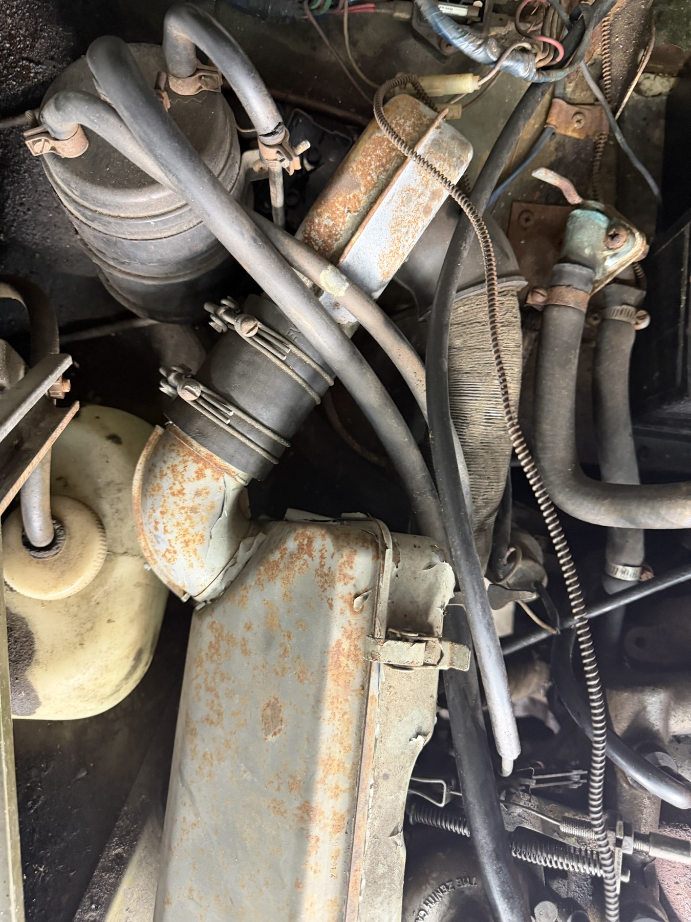
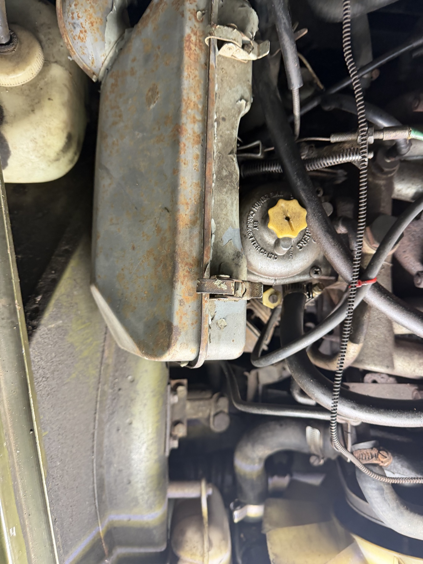
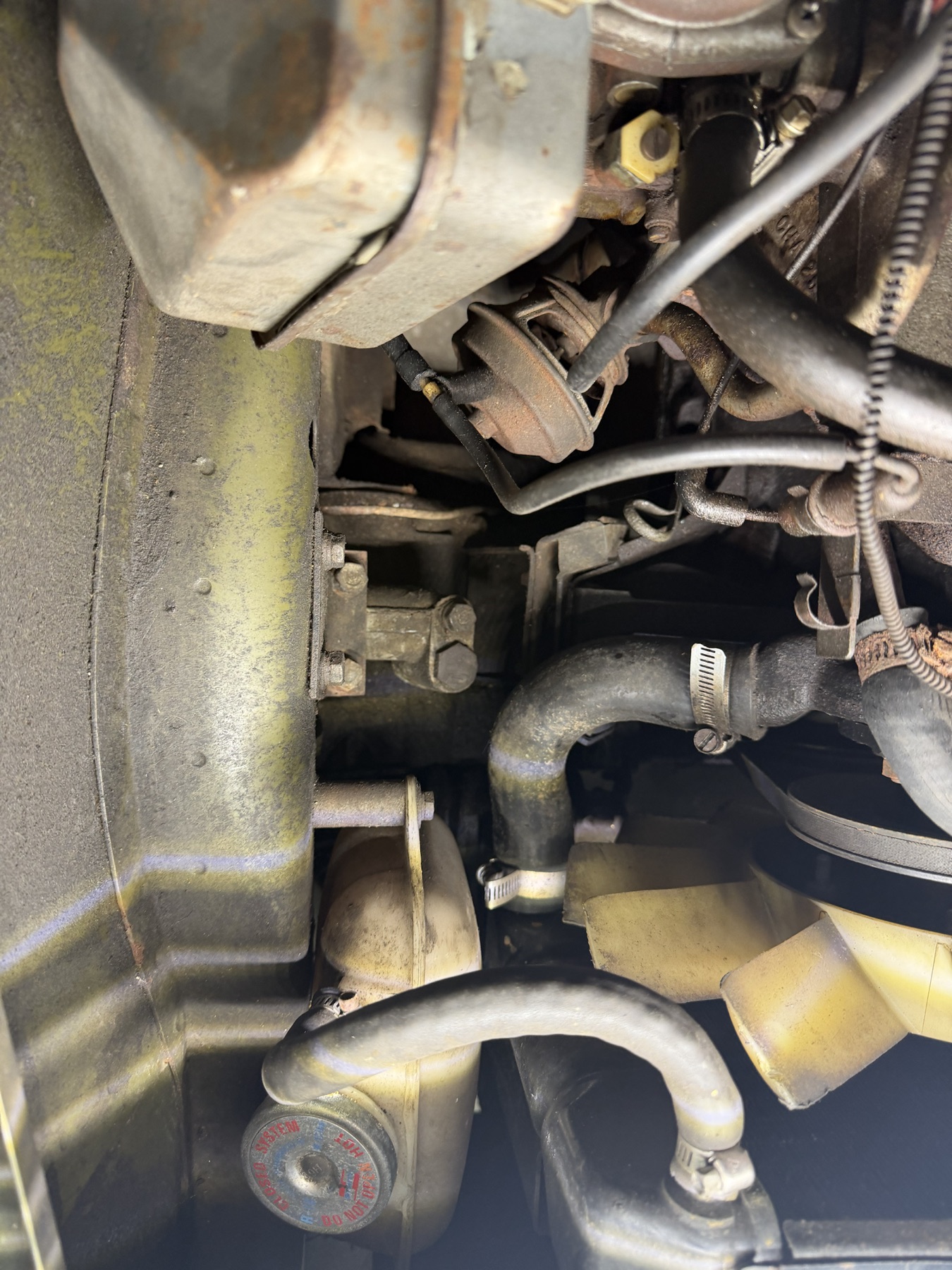
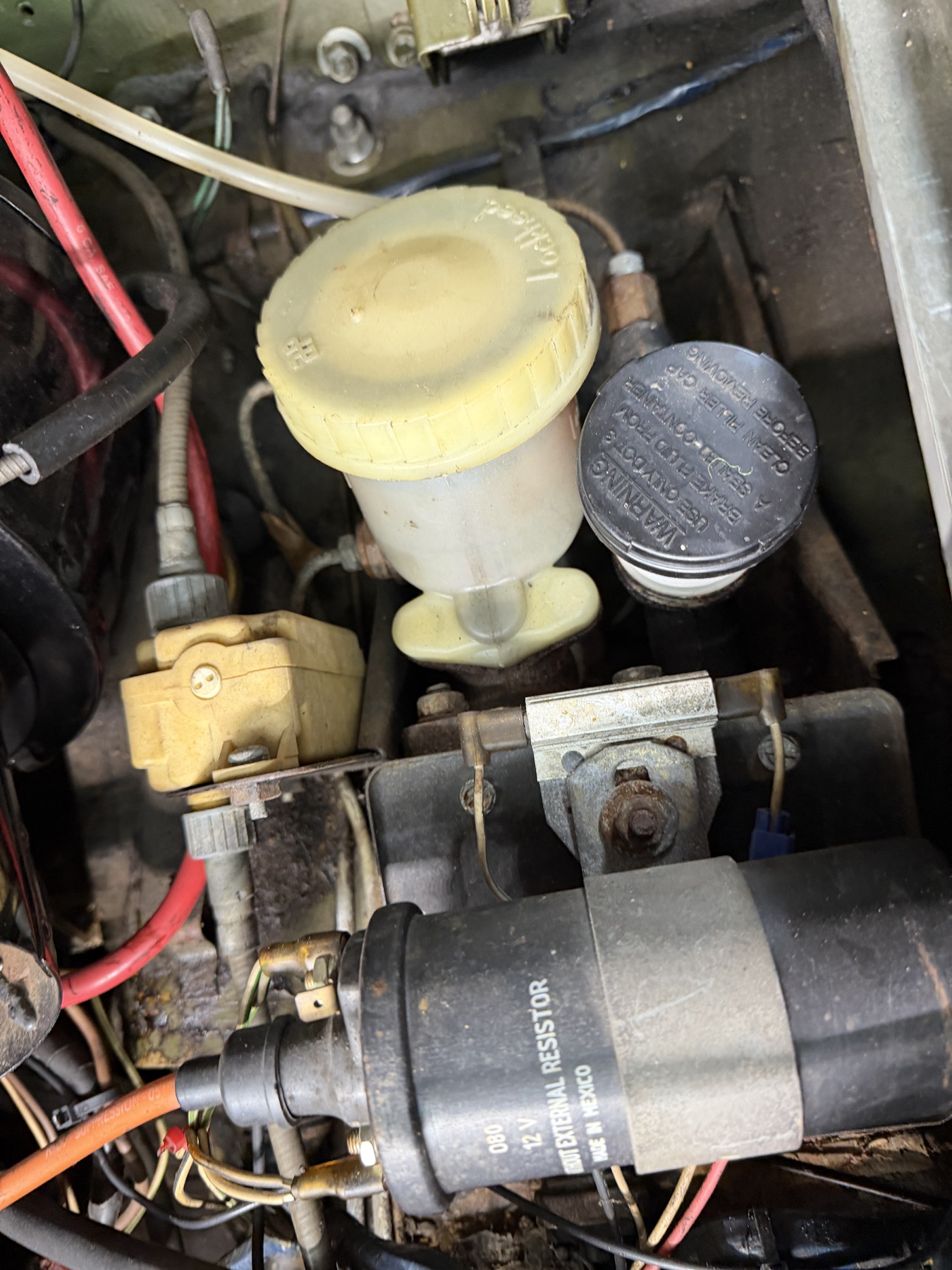
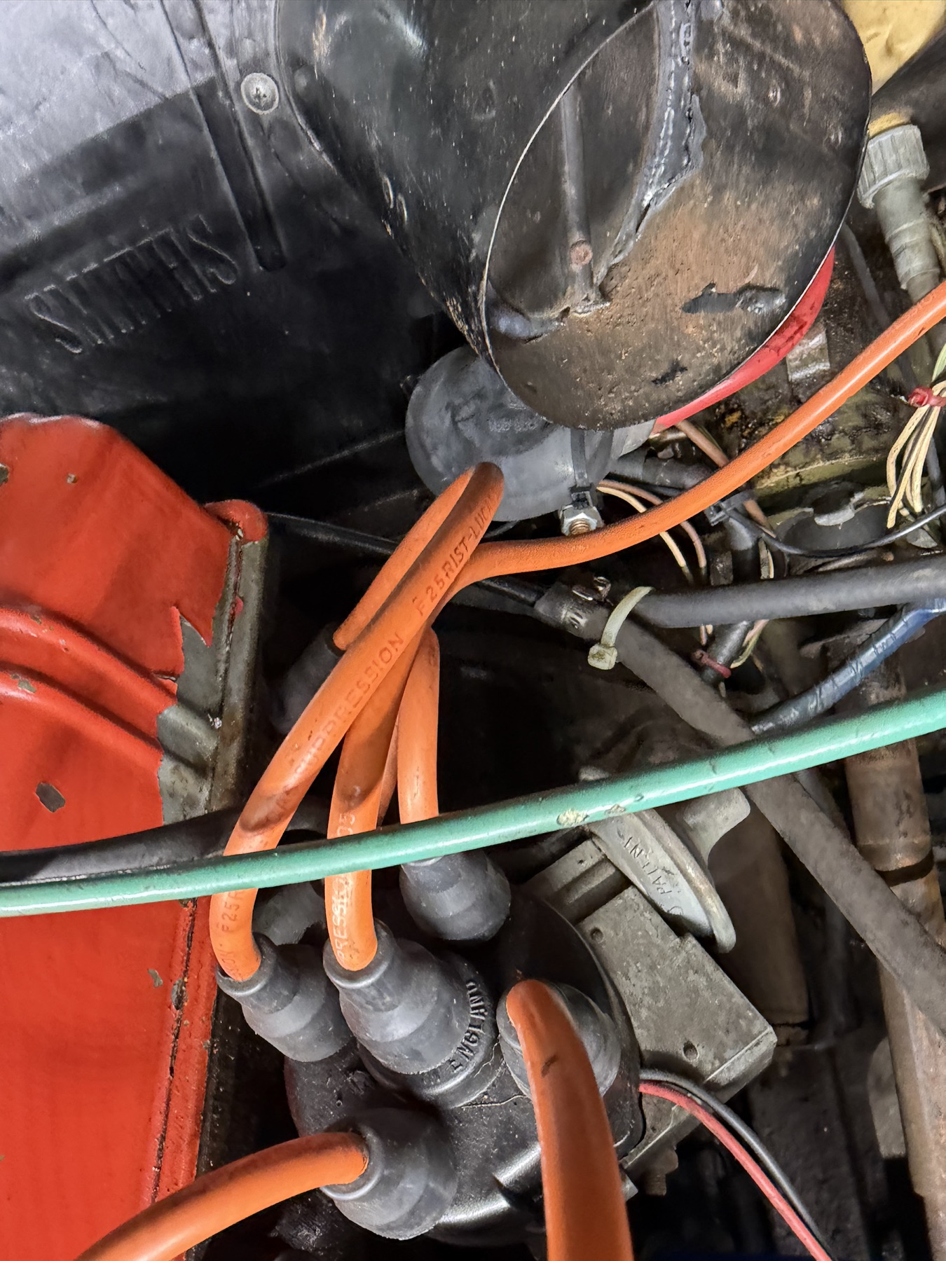
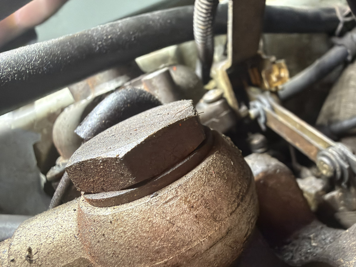
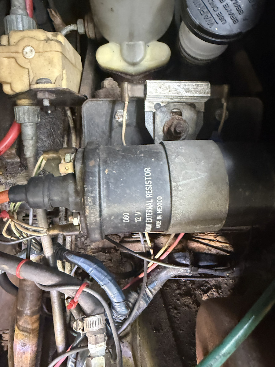
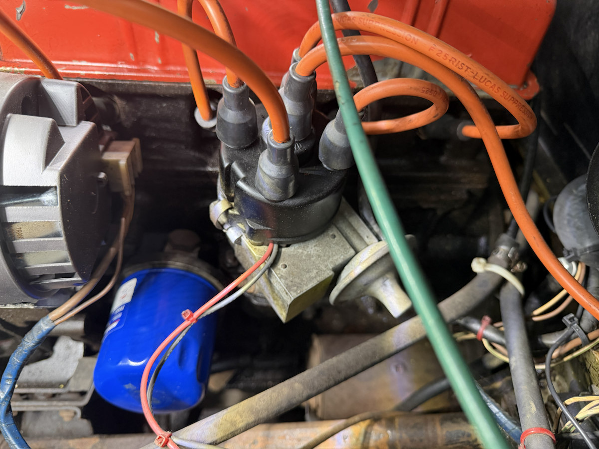
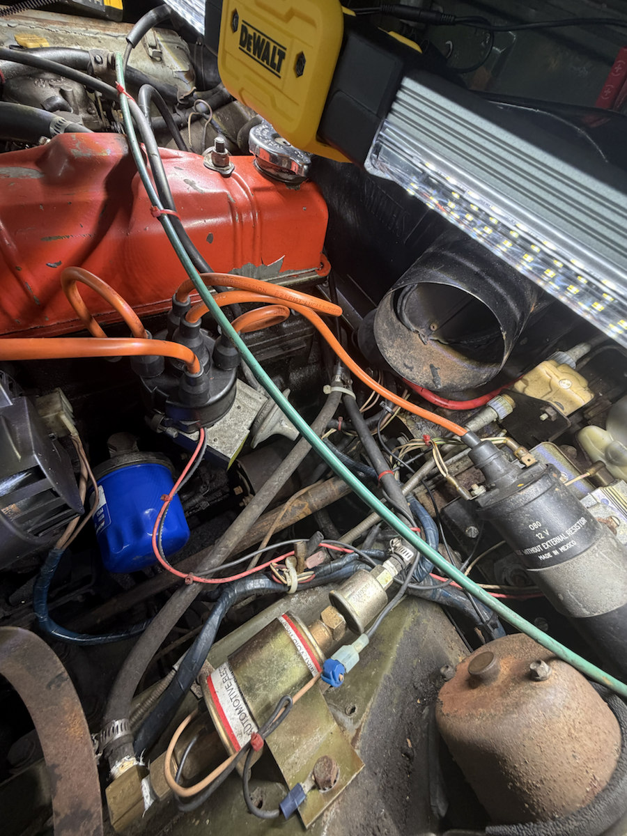
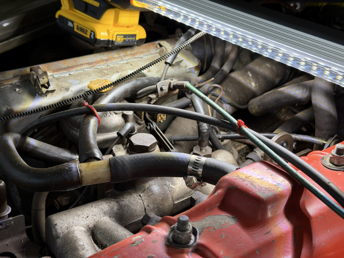
IMG_7036Additional installed context: yellow damper cap, cover/body joint and lower metal features. Uncalibrated; identities and hidden connections remain unverified. Read the evidence limits ↗ · Open photo markers ↗IMG_7034Air-cleaner case, retaining clips, yellow damper cap and surrounding hoses. Supports visible arrangement; no calibrated dimensions or complete hose destinations.IMG_7035Sharper carburetor side, lower castings, slotted adjuster-like feature and bracket eye. Exact control identities, settings and dimensions remain unverified.IMG_7037Cover/body seam and lower hexagonal feature are clearer than IMG_7036. Function, threads and fitted part identity remain unverified.IMG_7038Blue spin-on filter beside distributor and alternator, with nearby wiring and a cross-car member. Hidden adapter thread and seal seat remain unverified.IMG_7039Distributor cap, orange lead boots, retaining clip, side housing and diaphragm-shaped unit. No firing-order assignment, timing setting or internal ignition identity is established.IMG_7040Coil visibly reads 080, 12 V, WITHOUT EXTERNAL RESISTOR and MADE IN MEXICO. Corrects earlier partial external-resistor transcription; actual ballast wiring and electrical compatibility remain unverified.IMG_7041Bracket plates, fasteners and rubber block beneath the alternator, beside the filter and cross-car shaft. Stronger mount-area context; fitted part numbers, hidden attachments and dimensions remain unverified.IMG_7042Rust-colored manifold-area casting, round diaphragm-shaped housing, rigid pipe union and nearby carburetor-side hardware. Exact valve/pipe identities, threads, hidden flange and routing remain unverified.
Intake and cooling front
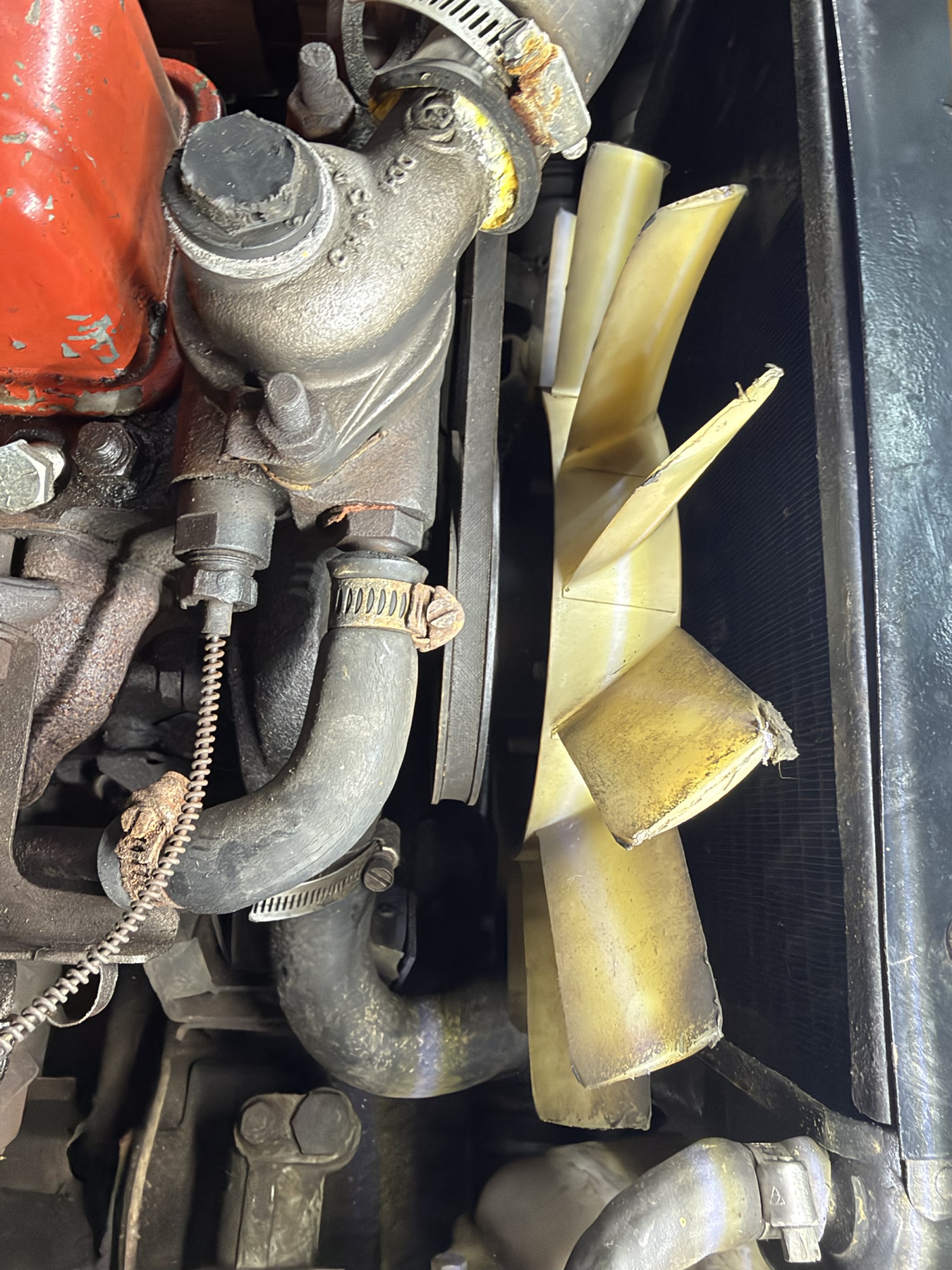
The metal air cleaner, elbow and black flexible coupling are distinct from the rear Smiths heater. The close fan views make several irregular tips easier to see.
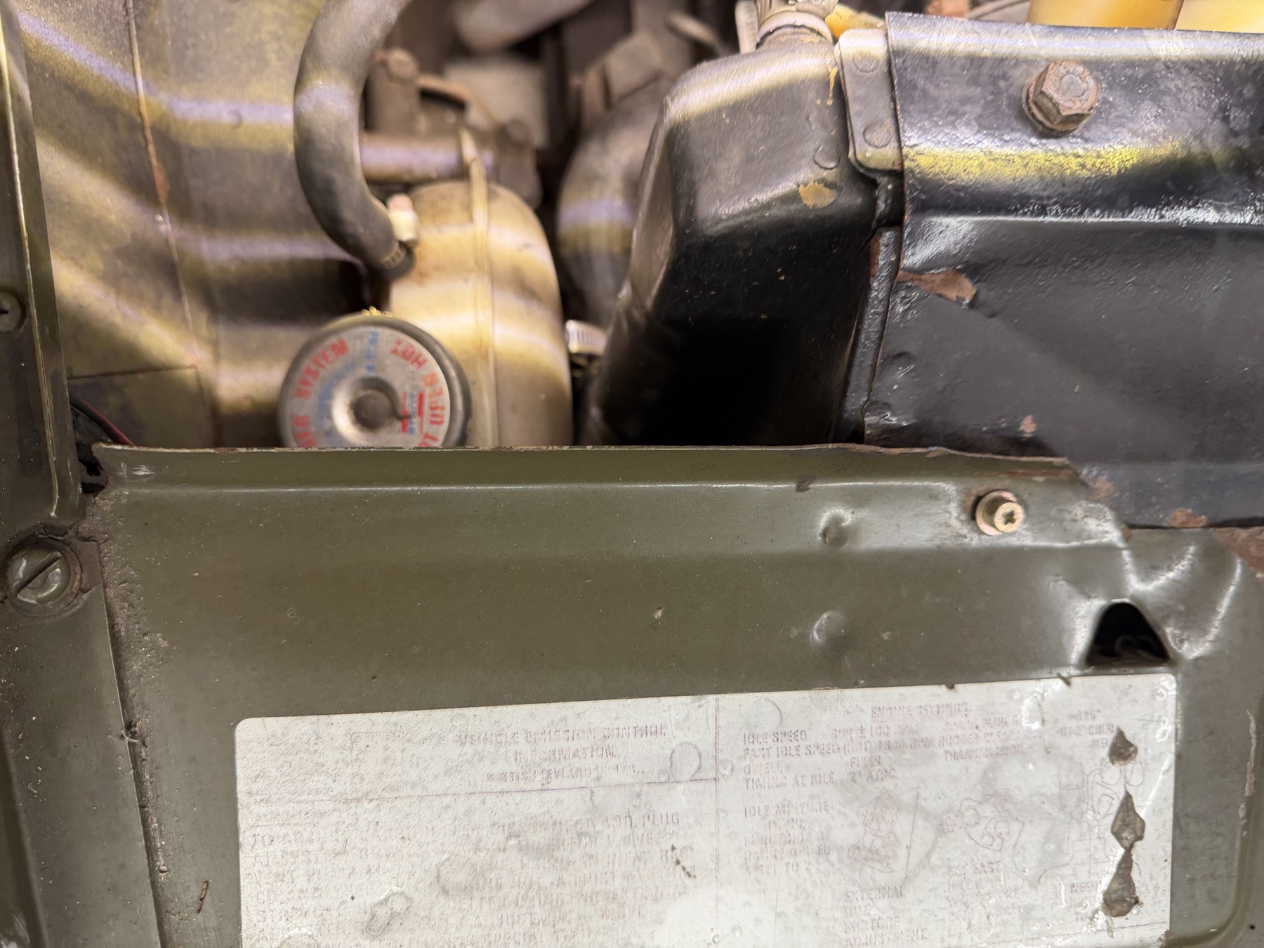
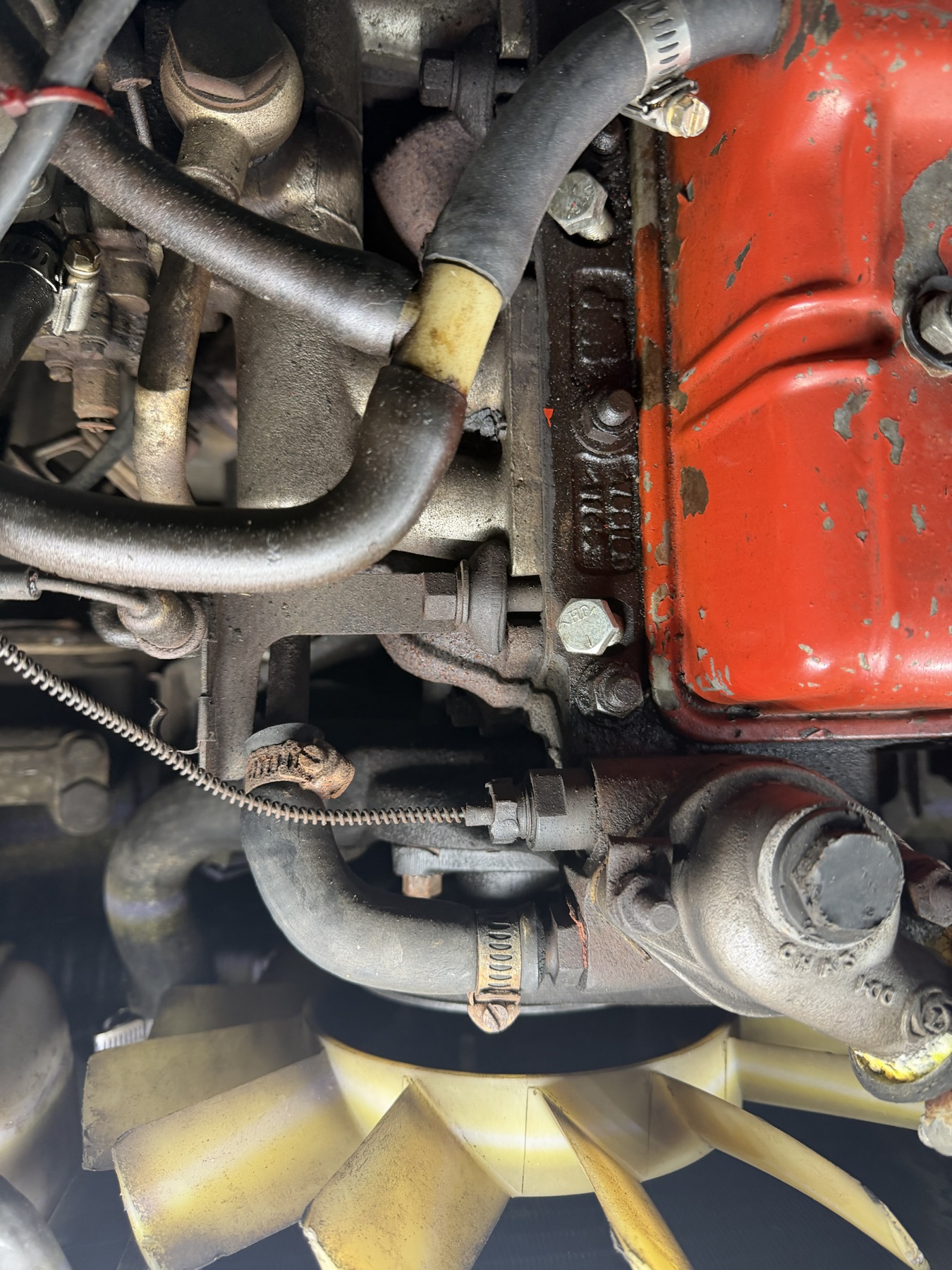
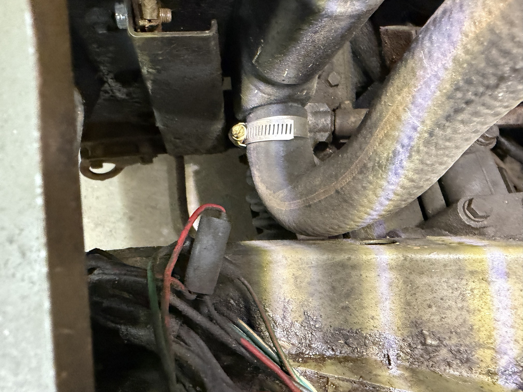
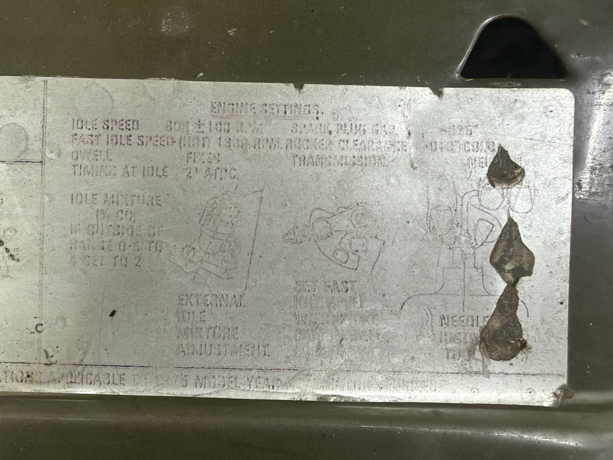
IMG_6885Air-cleaner case, elbow, coupling and separate hose-connected canister.IMG_6886Case lid and clips beside the carburetor; its element and number remain unverified.IMG_6887Lower intake and cooling area with tank, hose, shroud and fan.IMG_6888Faded under-bonnet label. Do not transcribe unreadable text as a specification.IMG_6889Front head casting, thermostat housing, hoses and fan.IMG_6890Two rear heater hose connections relative to the rocker cover.
Heater, cover and charging
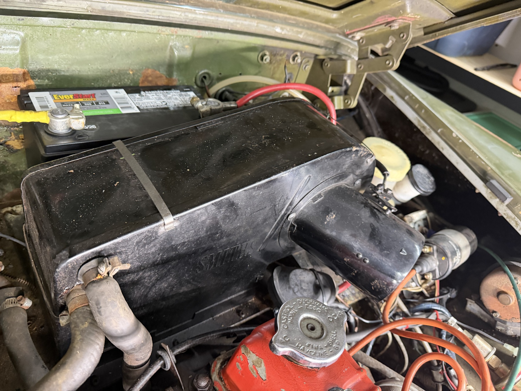
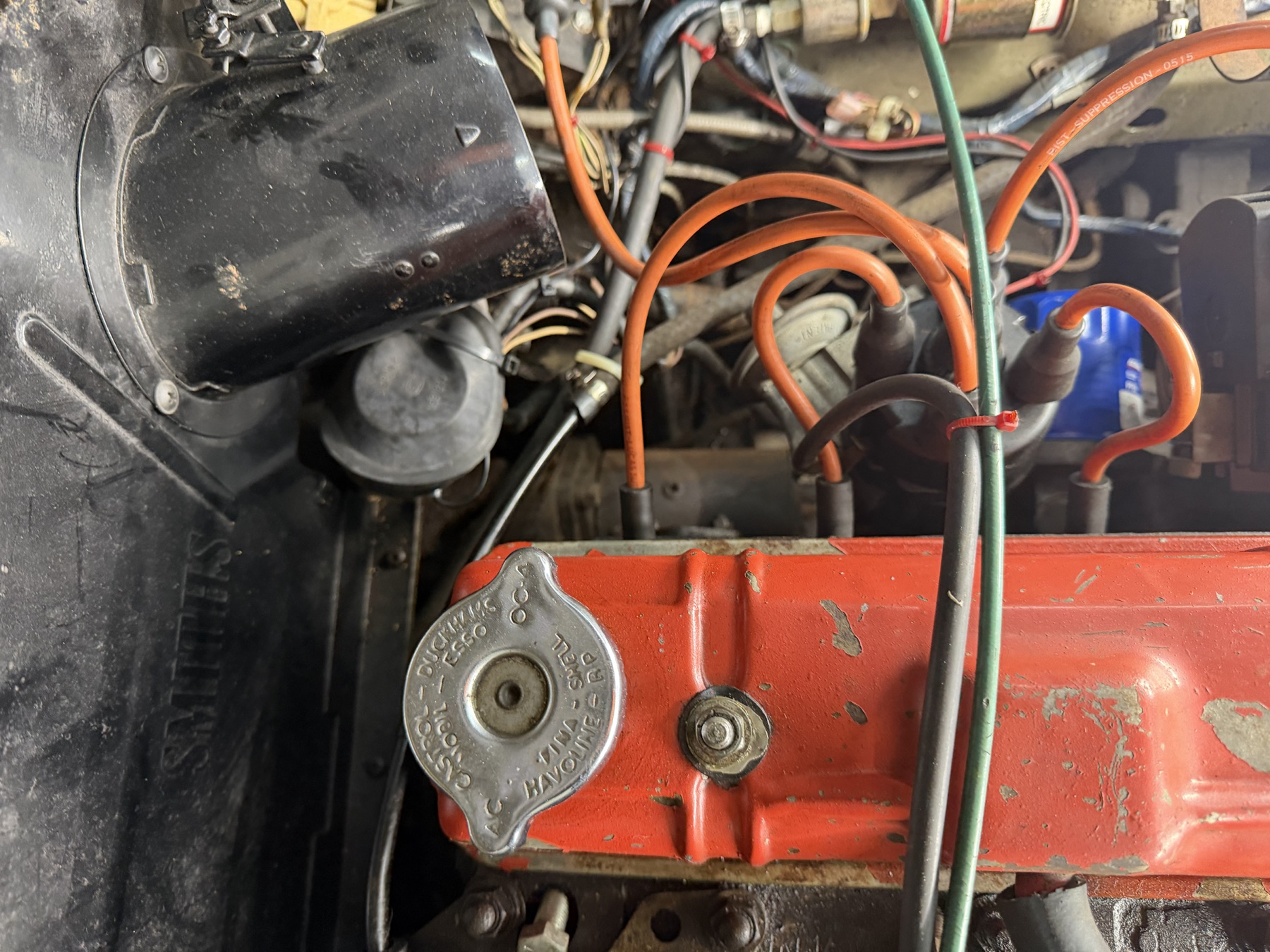
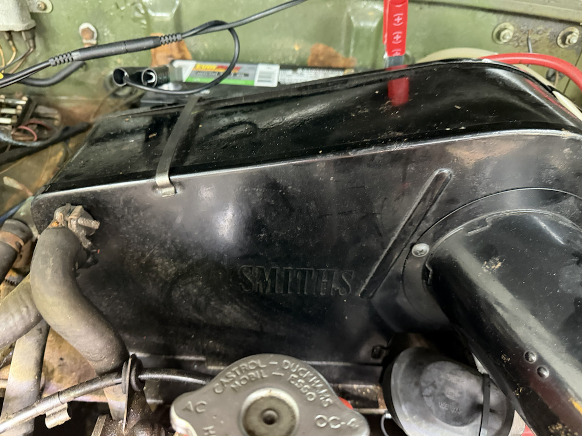
SMITHS is molded into the rear black case. The red cover's fitted cap has broad metal grips; the earlier CAD cylinder did not match it.
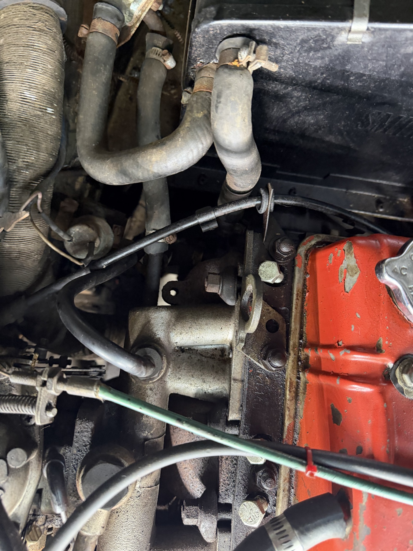
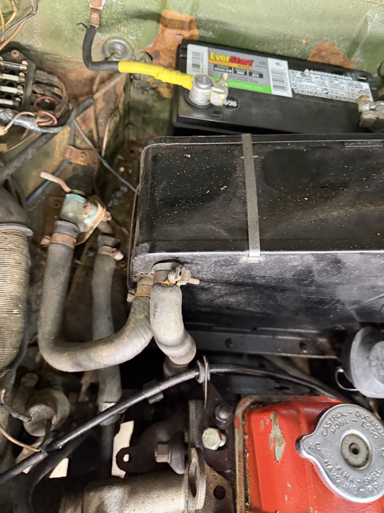
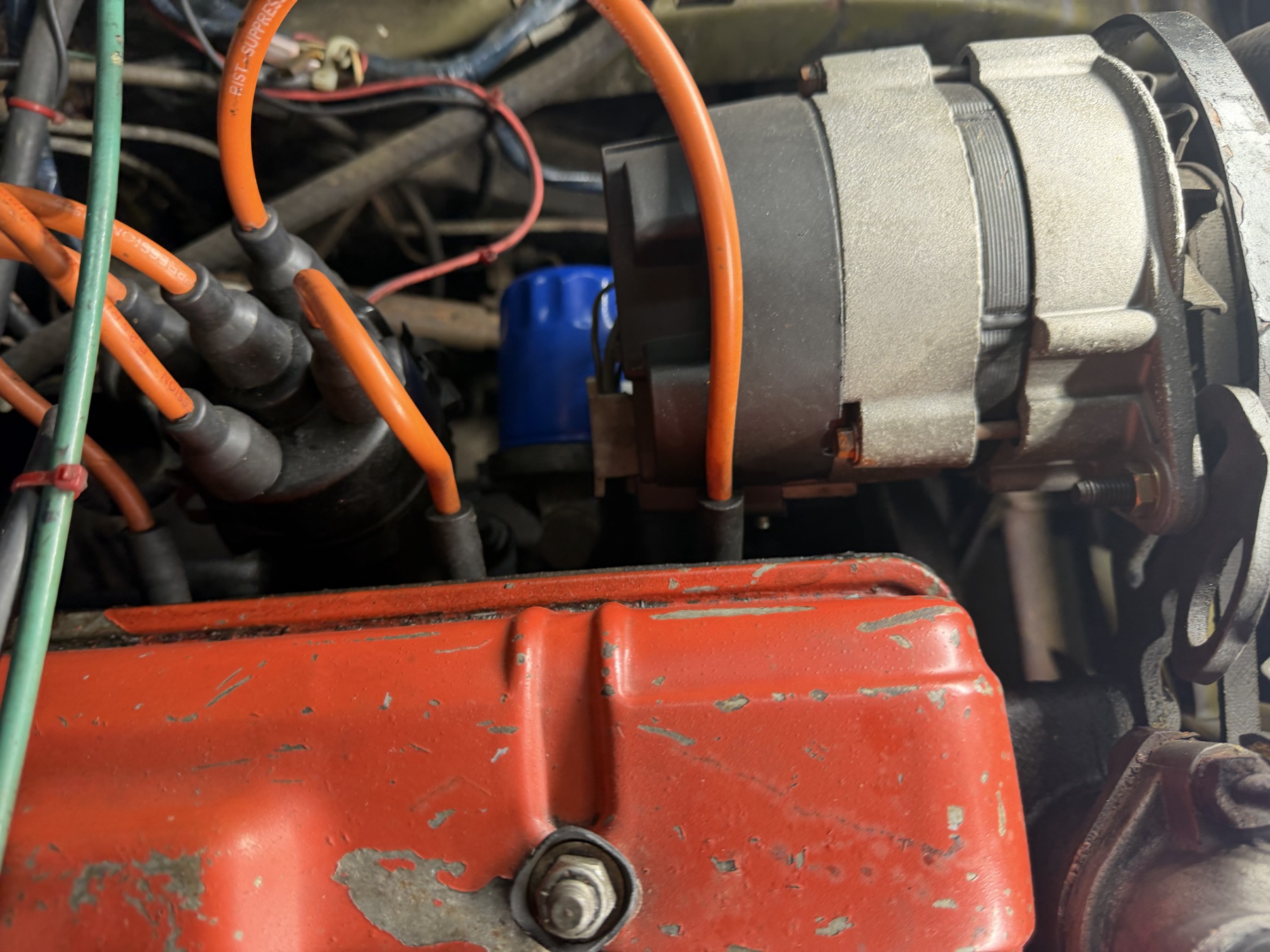
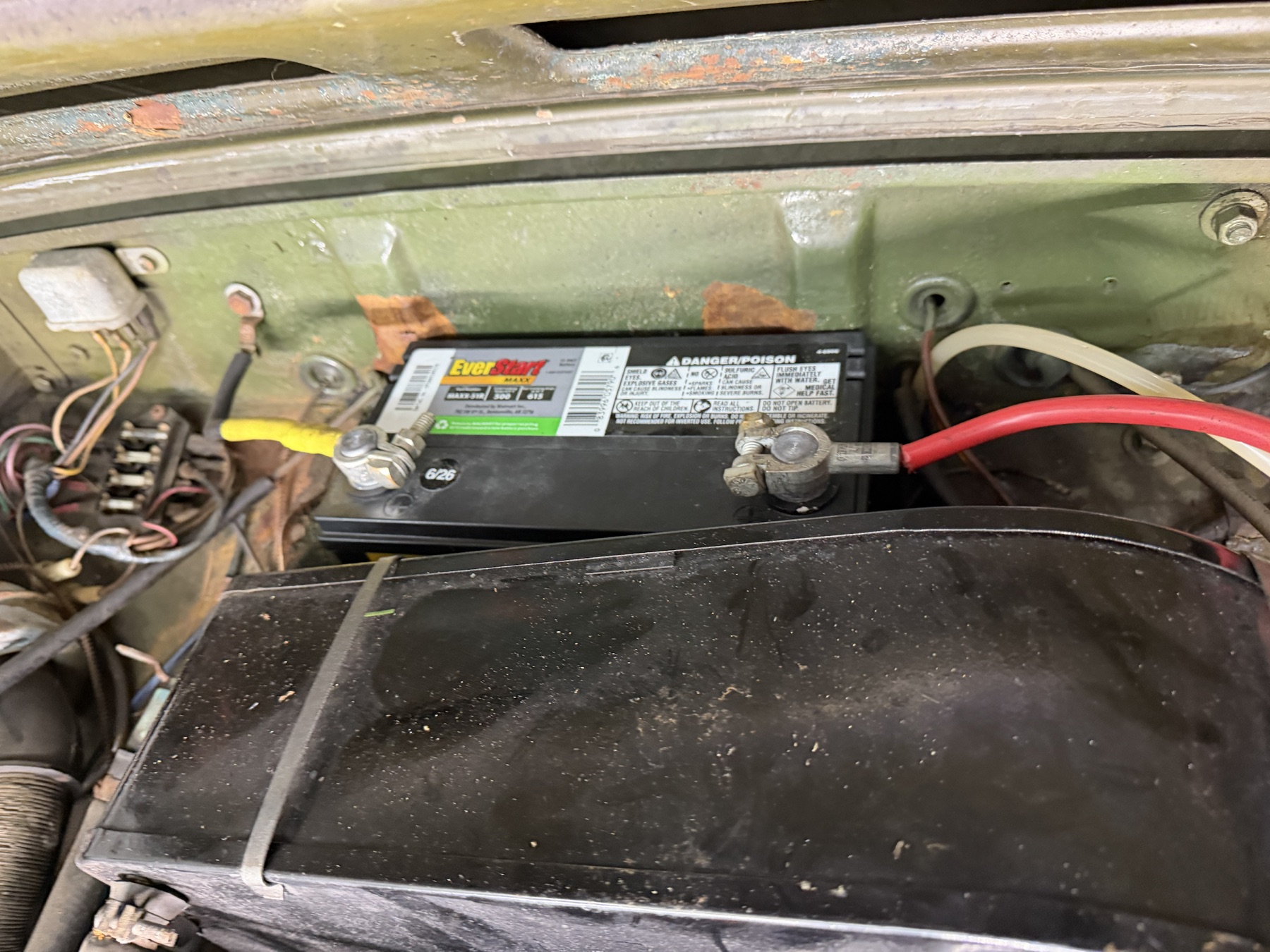
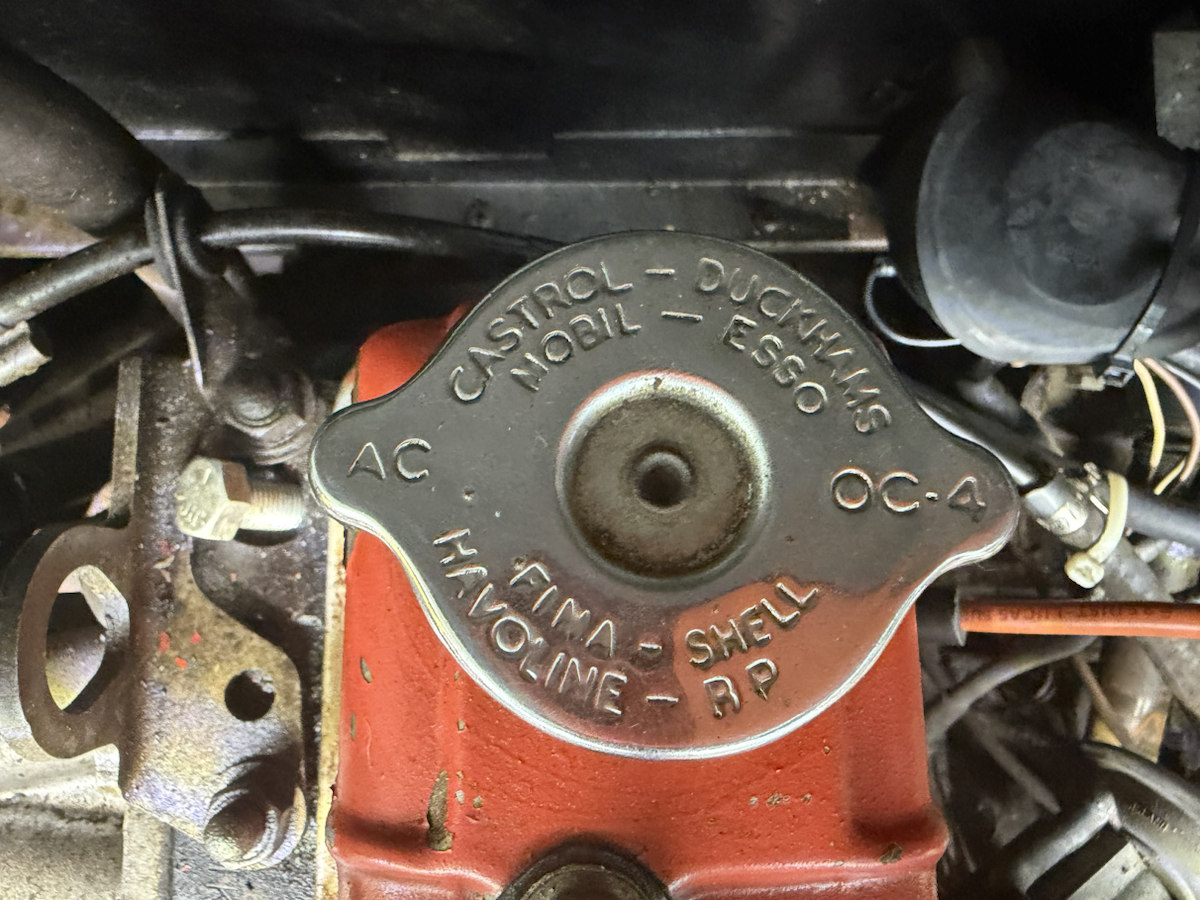
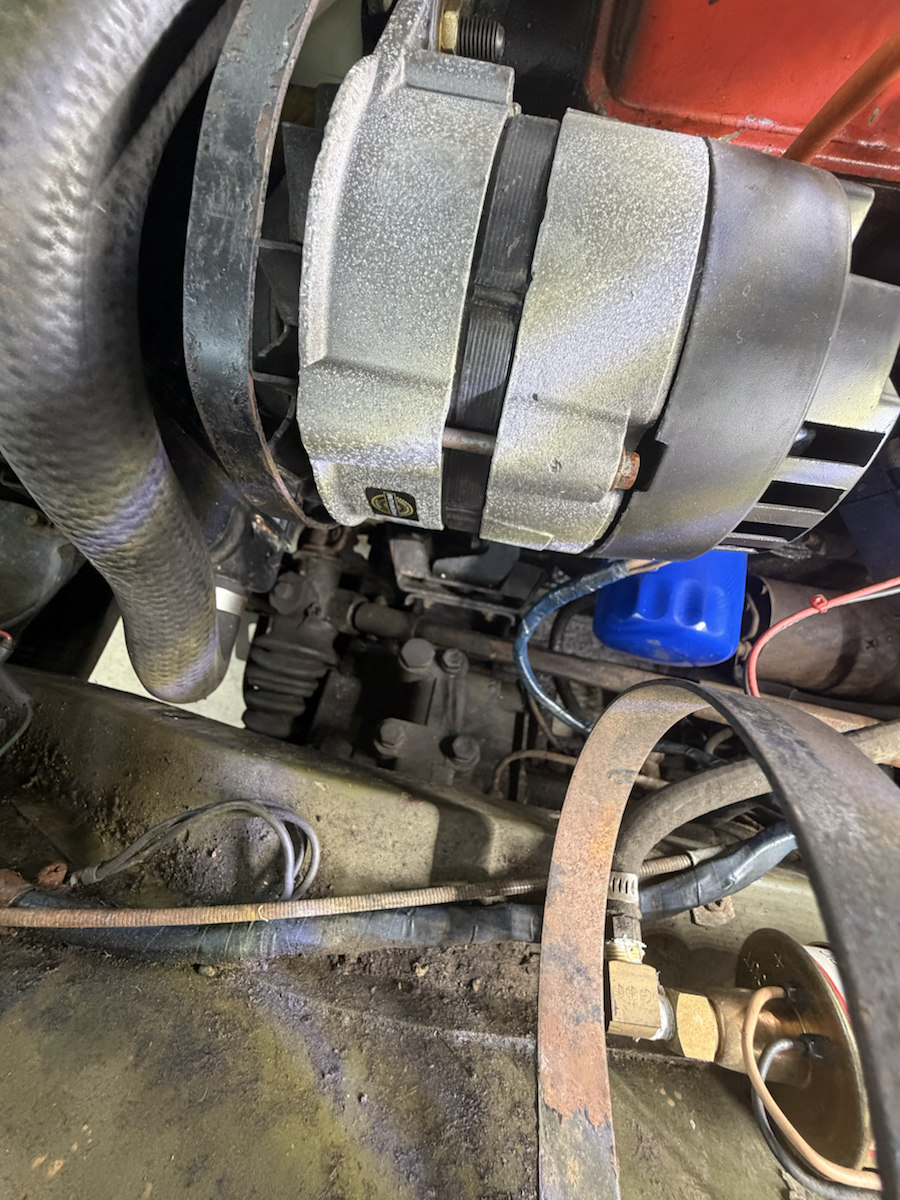
IMG_6891Heater case, coolant hoses and battery near the bulkhead.IMG_6892SMITHS marking, round outlet and two heater hose connections.IMG_6893A silver two-grip cap stamped CAUTION REMOVE SLOWLY appears over the red cover, beside one hold-down. IMG_6856 shows a dark cap there; the silver cap’s fitment is unverified.IMG_6894Alternator case and mounts beside the distributor and red cover.IMG_6895Several fan tips show irregular missing material. Inspect every blade directly before running.IMG_6896Lower coolant hose, clamp and nearby wiring.
Filter, fuel, electrics and underside
These views locate fitted service parts and modifications. A visible maker or generic label does not establish the exact replacement number or safe procedure.
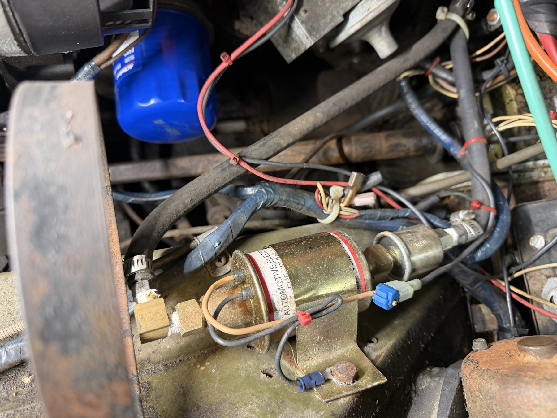
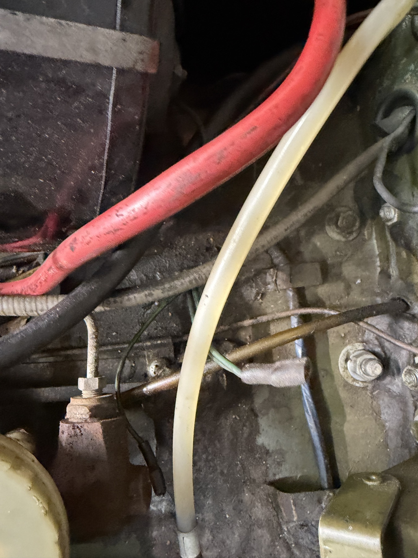
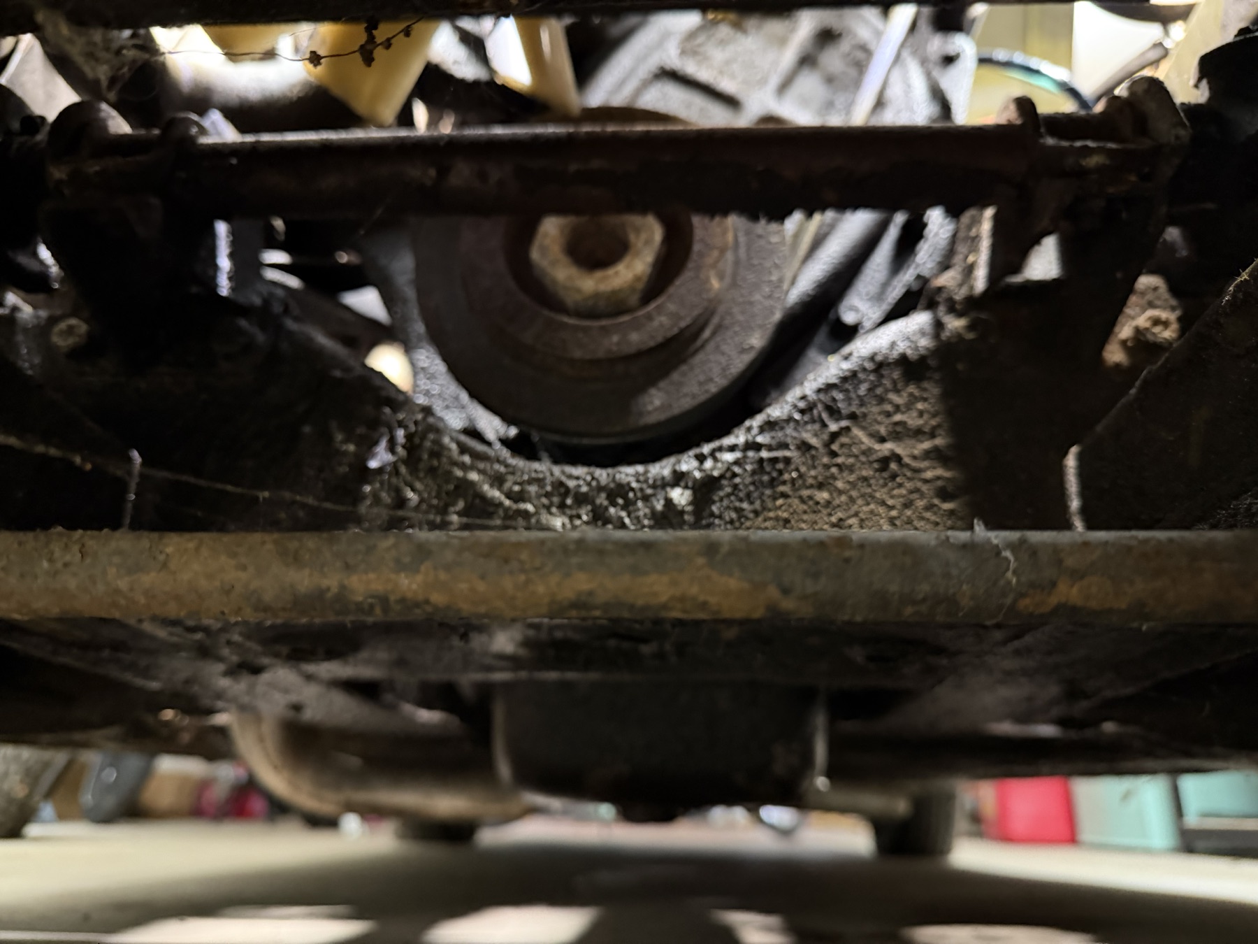
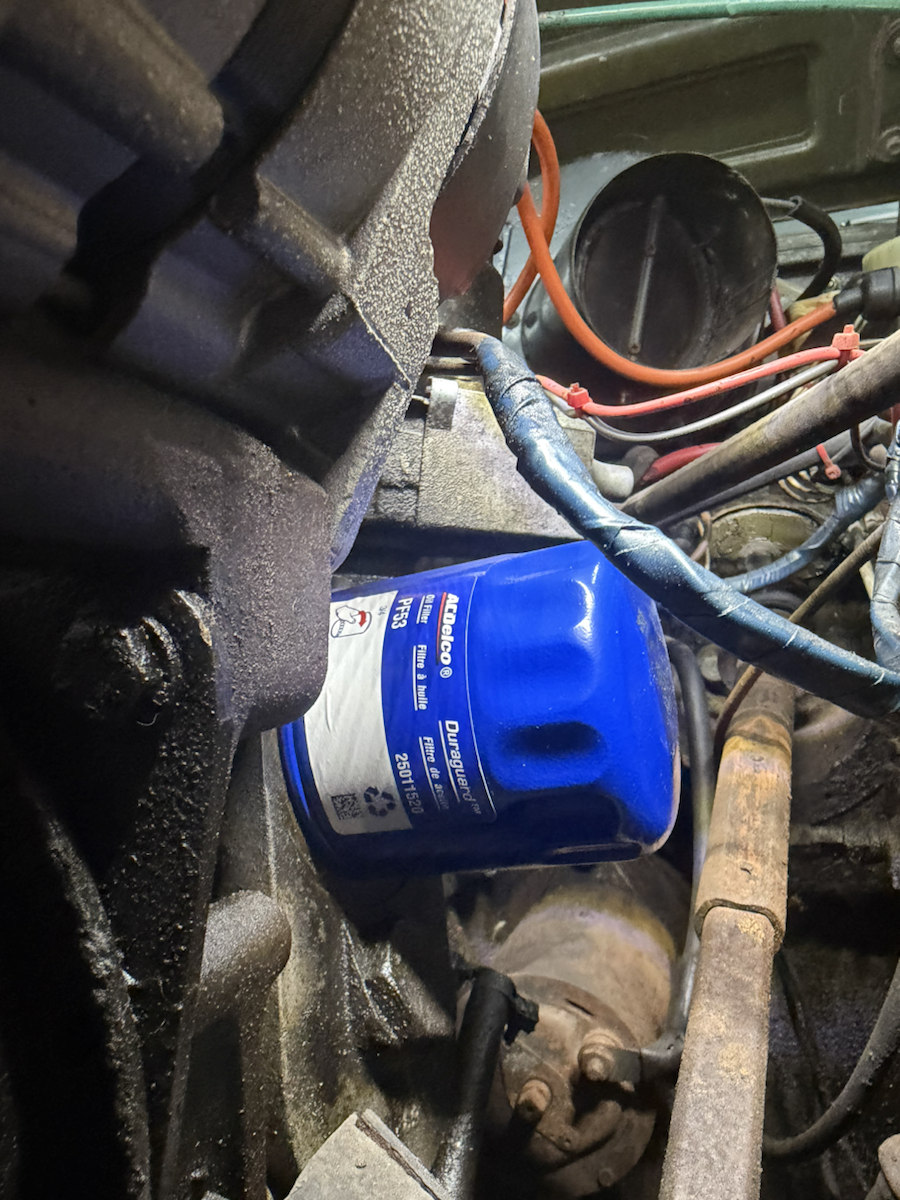
IMG_6897Blue ACDelco spin-on oil filter and surrounding mount area.IMG_6898Filter beside a labeled electric fuel pump, wiring and fuel fittings.IMG_6899Coil marked external resistor, two reservoirs and nearby electrical parts.IMG_6900Distributor leads and rear heater outlet; preserve the current lead route in photos.IMG_6901Battery terminals and bulkhead wiring relative to the heater case.IMG_6902Close hose and wire routing. Trace each line on the car before assigning it a function.IMG_6903Low front underside view. The dark image does not establish hidden component condition.
New stamped and underbody views · IMG_6907–6919
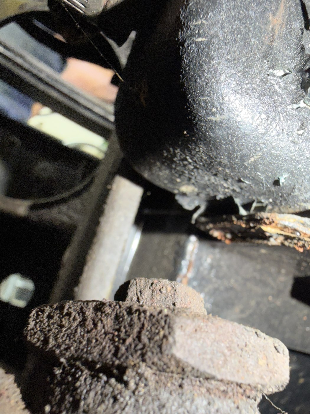
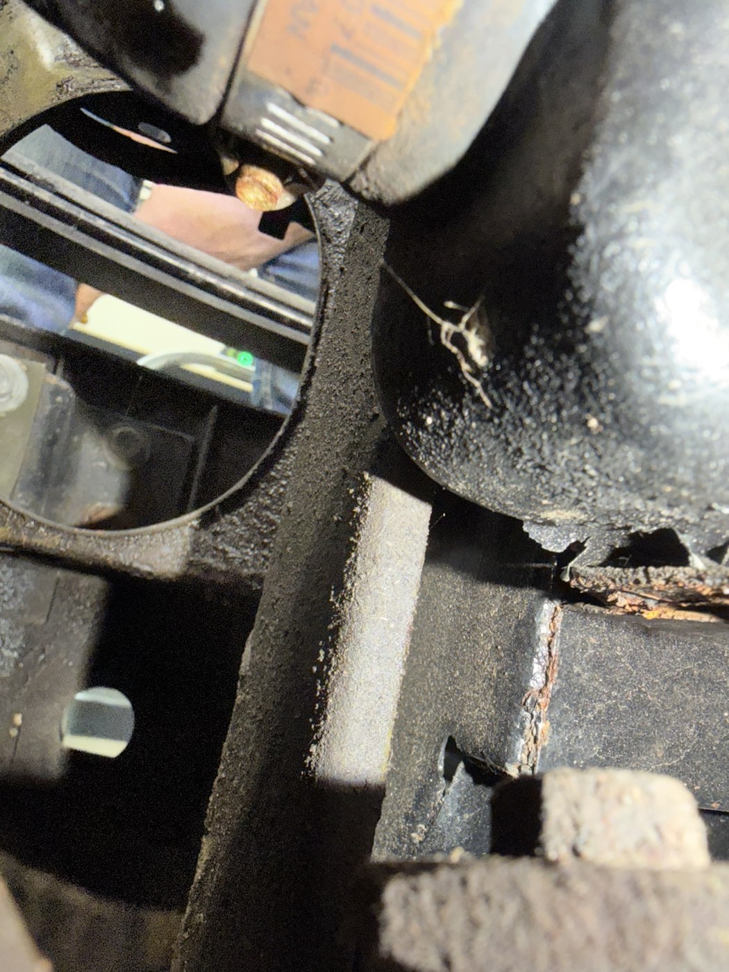
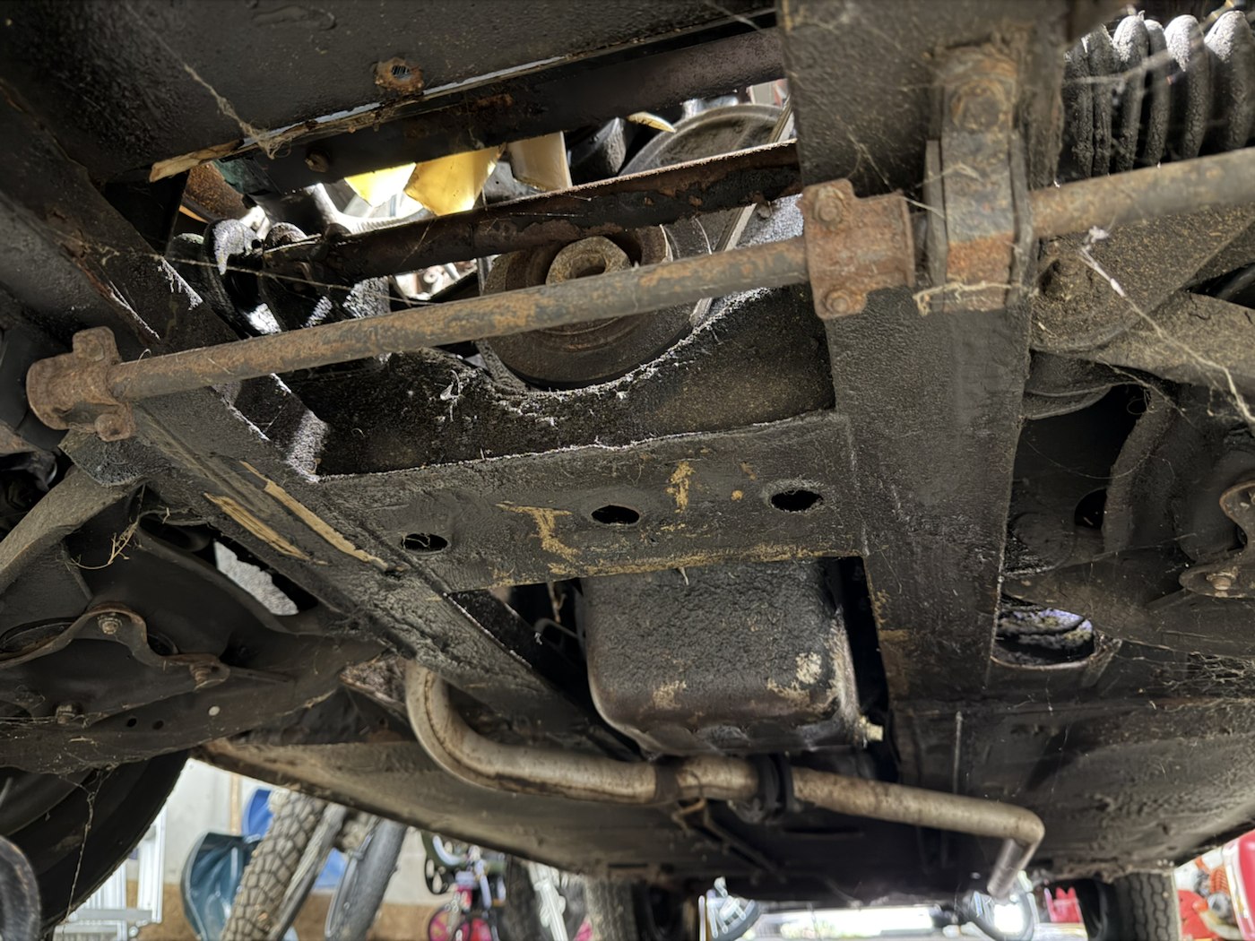
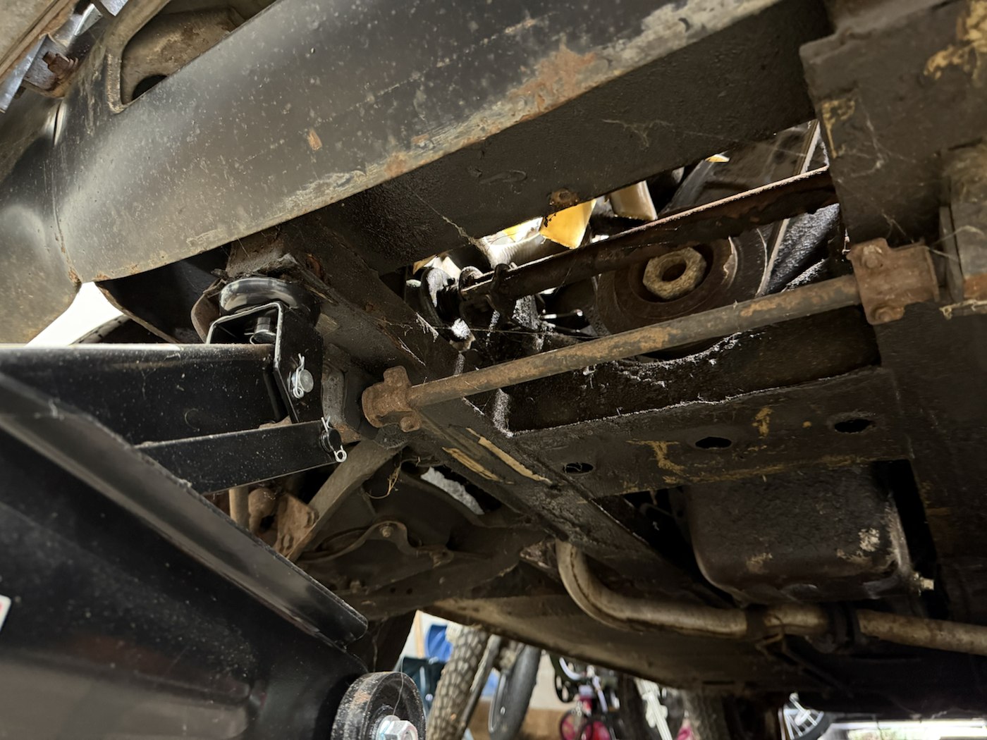
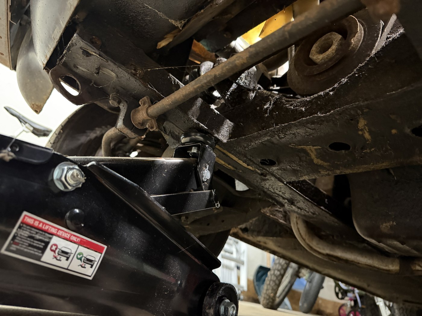
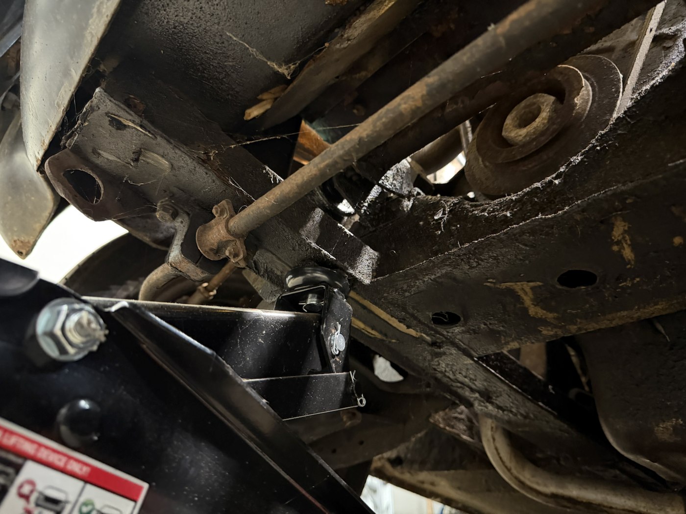
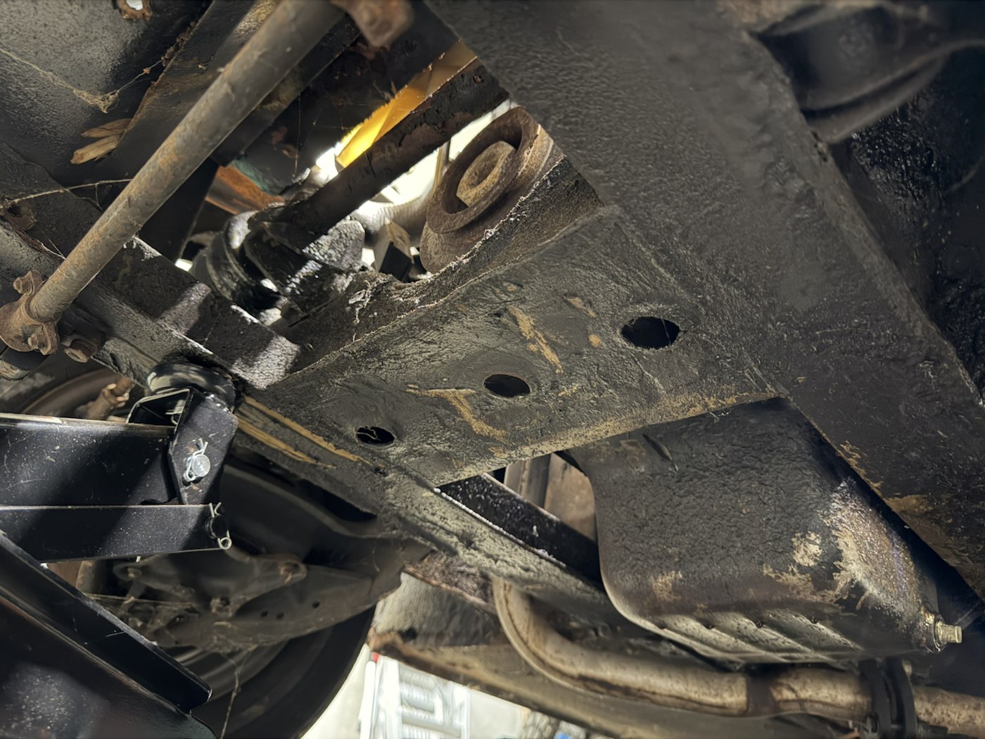
One close image shows raised marks on a casting beside the rocker cover, another shows a stamped plate, and the remaining views survey the front underside and suspension. These help identify what to inspect and photograph next. No ruler or verified datum is visible, so they do not establish 1:1 dimensions.
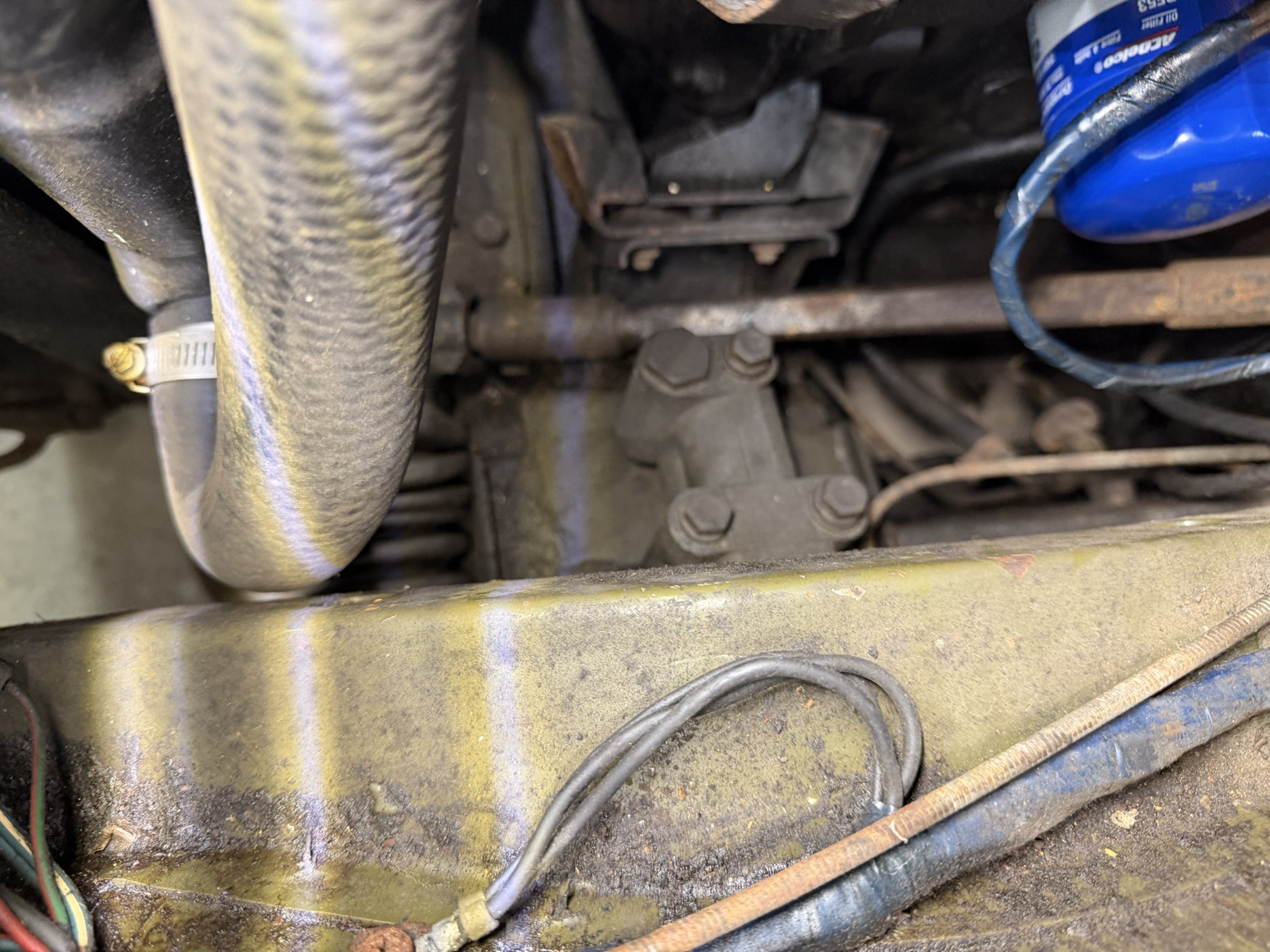
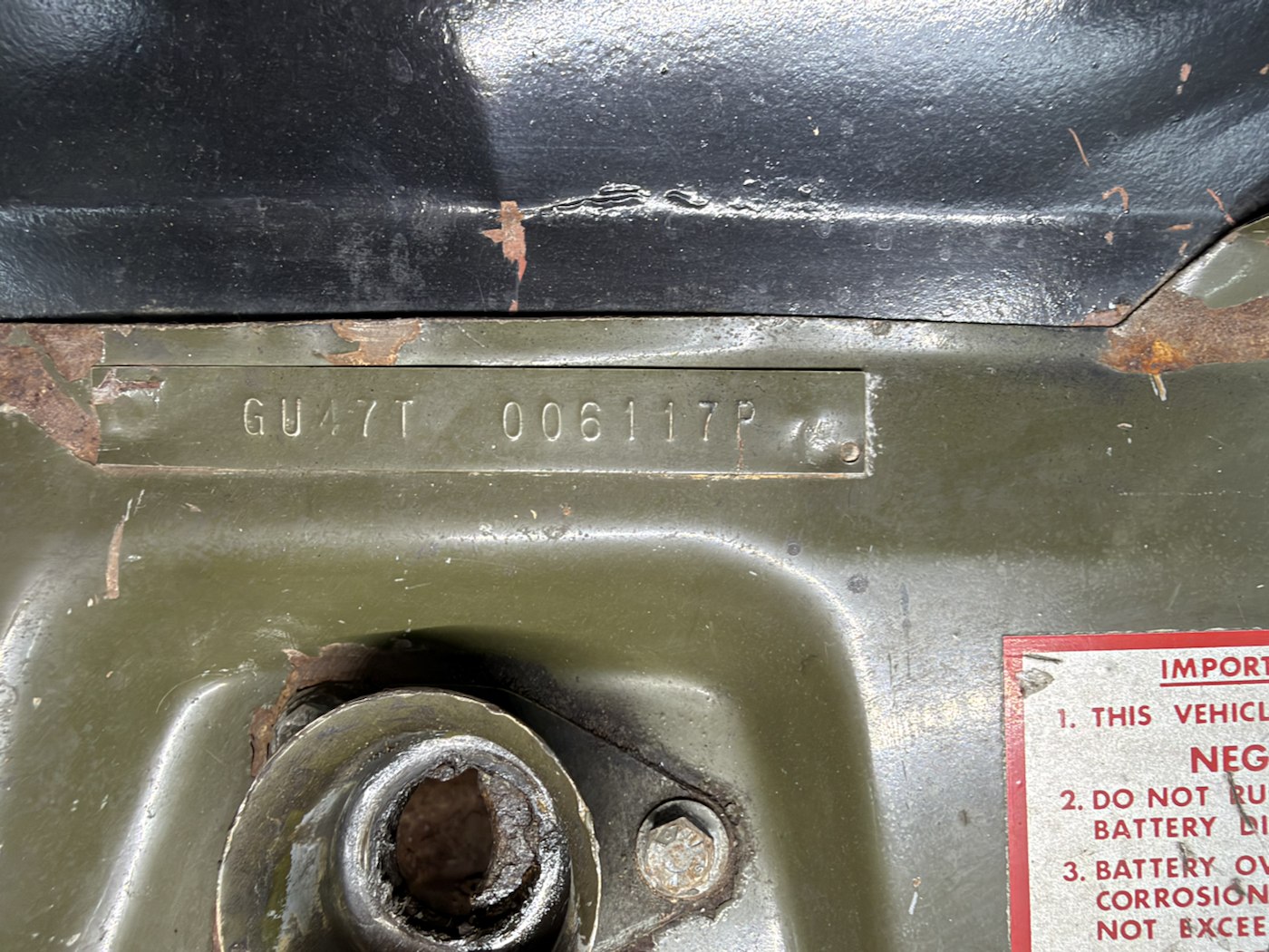
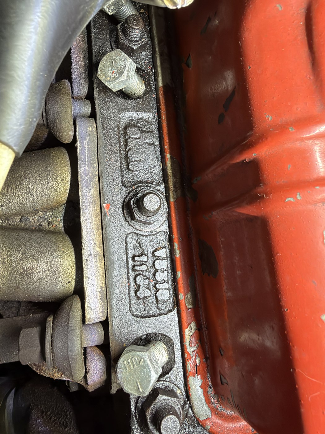
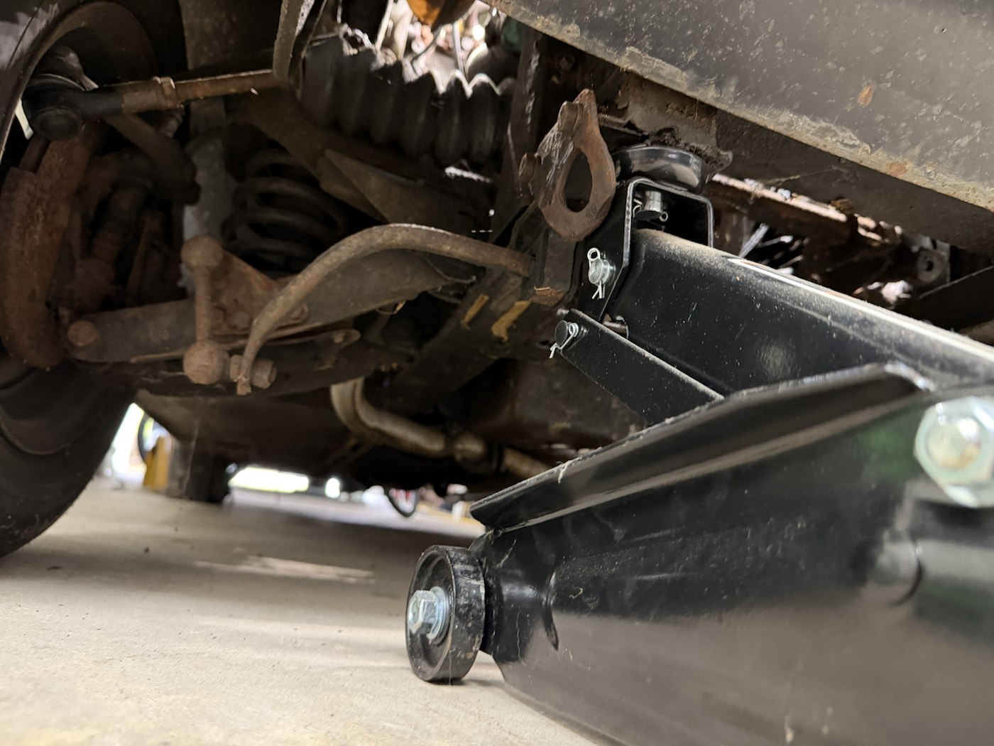
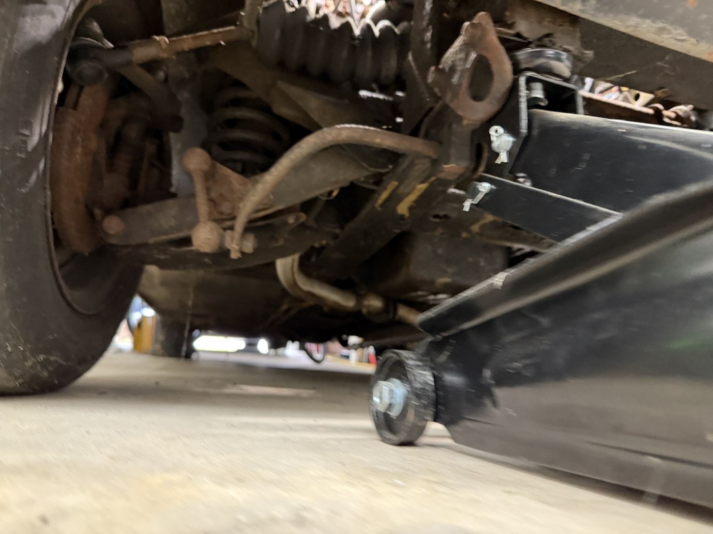
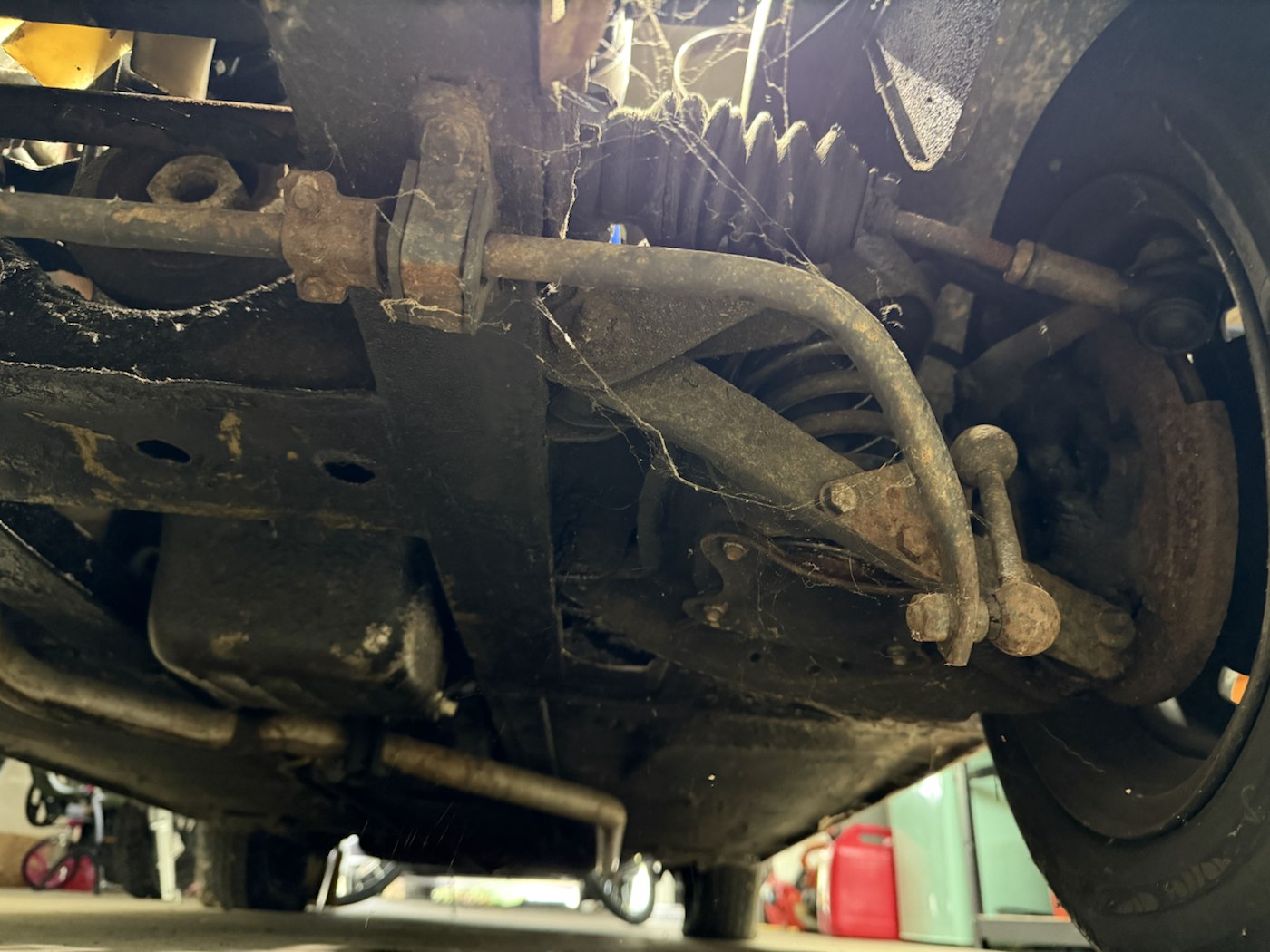
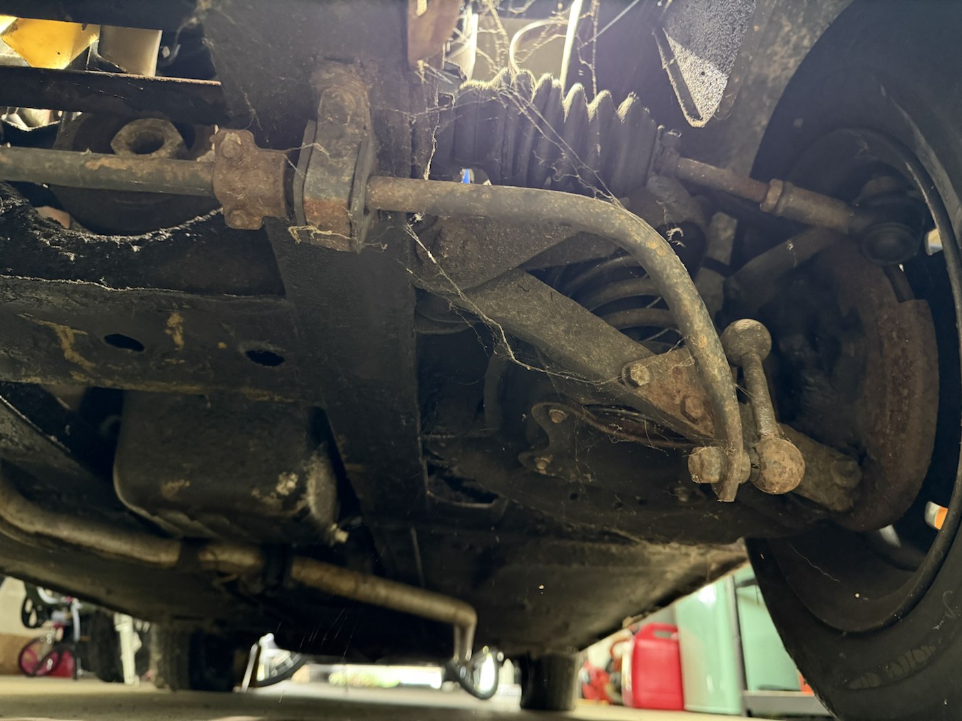
IMG_6907Front-panel plate. The owner transcribes it as GU47T 006117P; its function remains unverified, and this format does not match the documented GAN6-U Midget chassis number.IMG_6908Cast markings and fasteners beside the red cover. The visible surface may be a neighboring manifold or the head; identify the component and transcribe the marks directly before using them.IMG_6909Close view of a front underbody seam and nearby component. Record the location on a wider view before assigning damage or a replacement part.IMG_6910Second angle on a front underbody seam and bracket. Compare with IMG_6909 and inspect directly for any defect.IMG_6911Front suspension spring, lower arm and a jack nearby. The photograph records visible arrangement, not a lifting or support method.IMG_6912Wider front suspension view helps orient the spring, arm, wheel and nearby jack.IMG_6913Front underbody and suspension from another angle; useful for locating brackets and routing.IMG_6914Near-duplicate angle of the front underbody; compare where IMG_6913 is obscured.IMG_6915Cross-car view of the front underside with a transverse rod and broad panel; part identification still needs a wider reference.IMG_6916Steering/suspension area and mounting brackets from below. Trace each rod on the car before assigning its function.IMG_6917Low angle showing the jack, front structure and rod routing; do not infer a correct lift point from the image.IMG_6918Second view of the same area, useful where the jack obscures a bracket in IMG_6917.IMG_6919Closer view of a broad front underbody panel with holes and nearby rod; dimensions and condition need direct inspection.
Engine-bay details and fitted parts · IMG_6957–6976
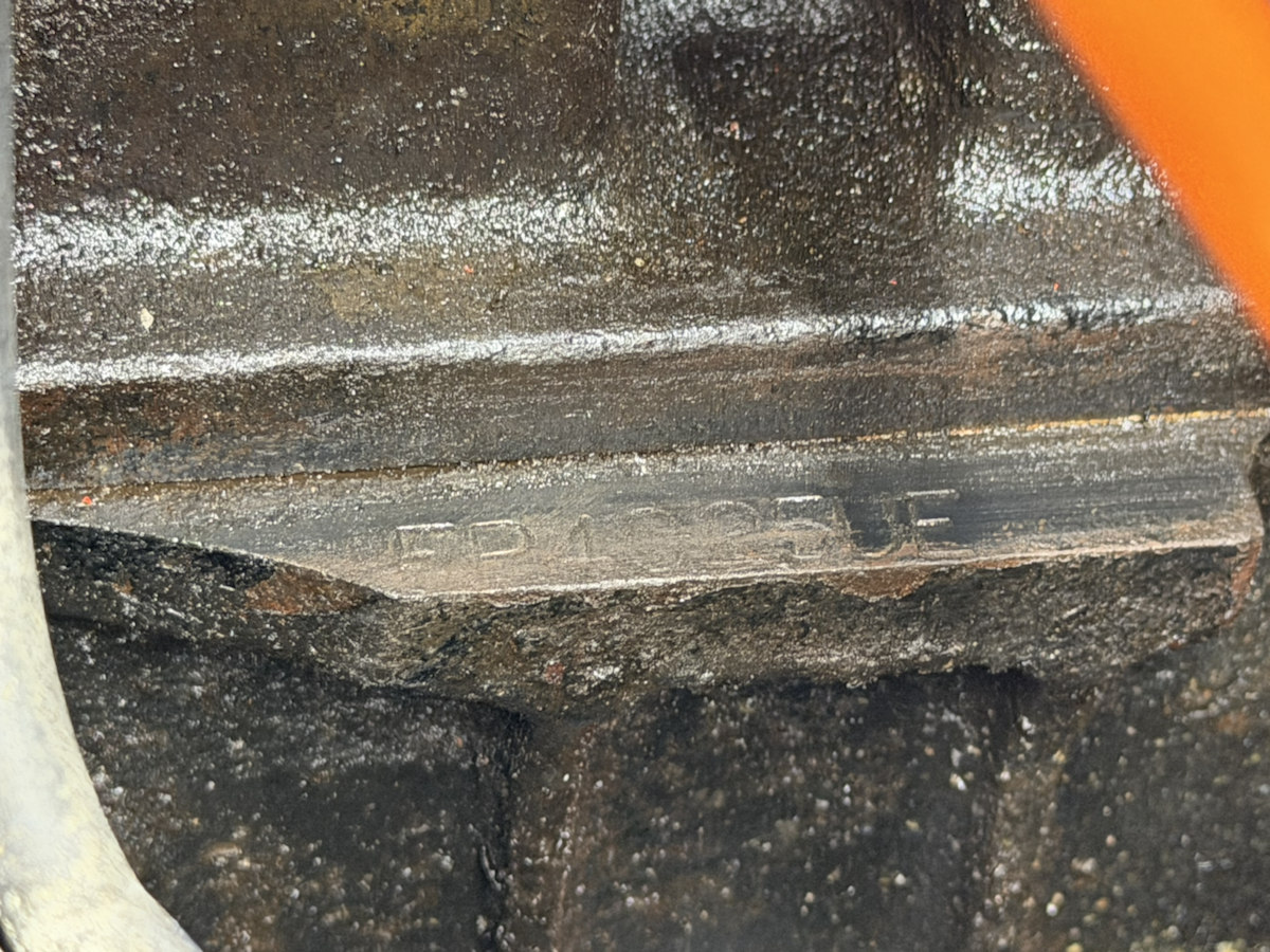
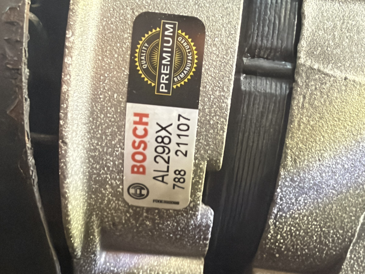
The block stamp in IMG_6968 is transcribed by the owner as FP4025UE. IMG_6976 clearly labels the installed alternator Bosch AL298X. Both are identification evidence; these photos lack a ruler, so they do not establish 1:1 dimensions or bolt clearance.
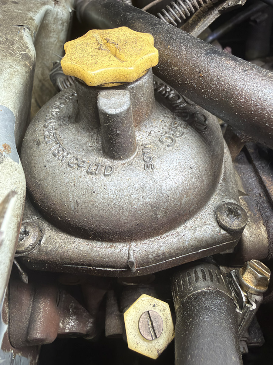
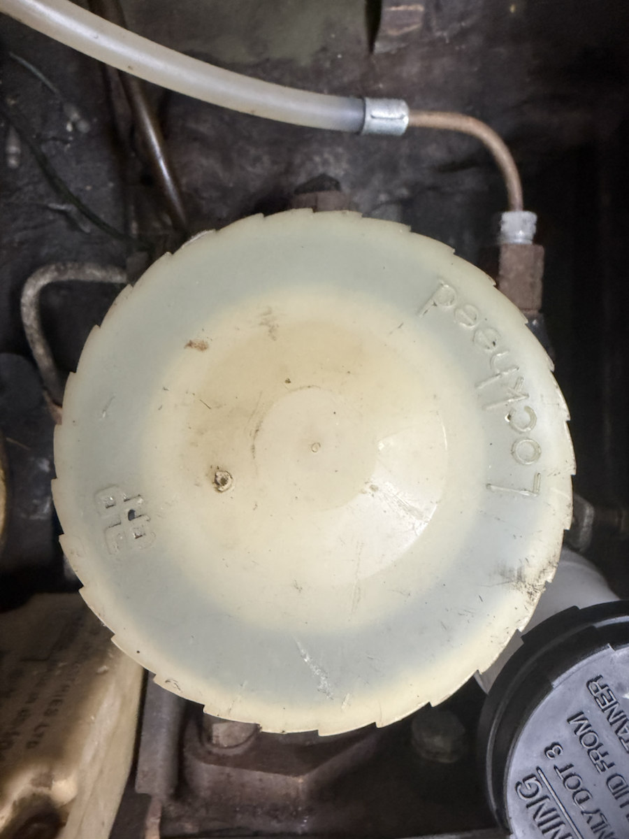
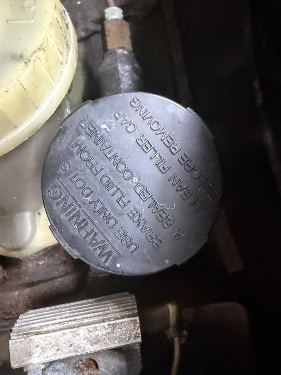
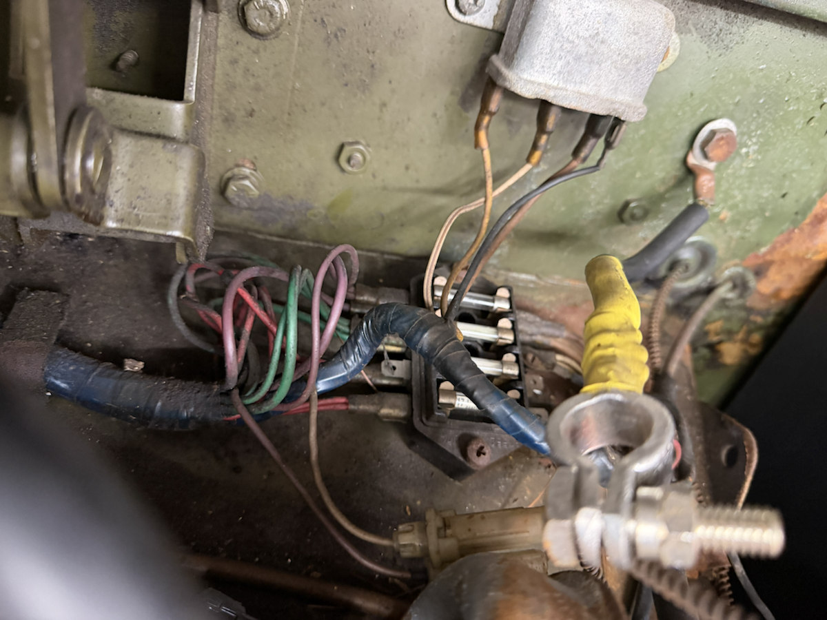
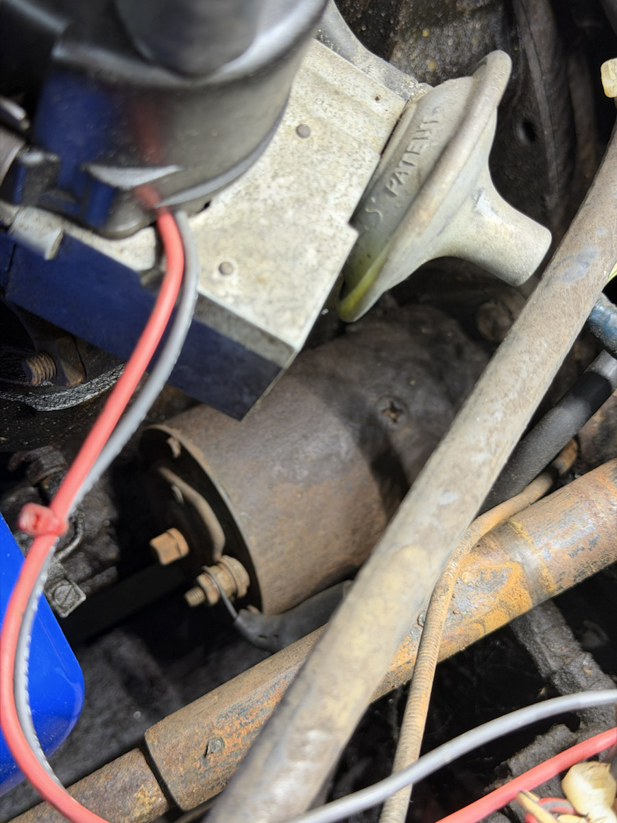
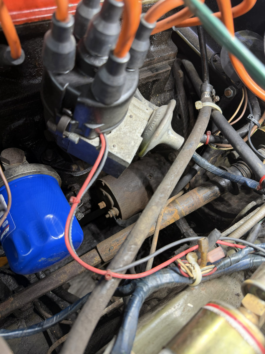
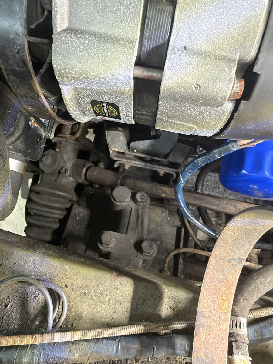
IMG_6957Faded under-bonnet emissions and tune decal; only independently legible values should be used.IMG_6958Zenith-Stromberg rounded dashpot cover and yellow lobed damper cap; record the carburetor tag before adjustment.IMG_6959Corroded cap and neck near the intake; identify this opening before any service.IMG_6960Larger pale LOCKHEED-marked cap beside a smaller black warning cap; trace both outlet lines before assigning brake or clutch roles.IMG_6961Black cap embossed with a DOT 3 brake-fluid warning beside the pale reservoir; circuit identity and existing fluid remain unverified.IMG_6962Smiths heater blower motor, bracket, and adjacent wiring and hoses.IMG_6963Smiths heater housing and rear bay wiring; compare its outlet to the prior heater views.IMG_6964Silver pressure-warning cap resting over the red rocker-cover area. Its text and position do not prove it is the oil filler cap.IMG_6965Bulkhead electrical connections and wire routes. Record each terminal before removal.IMG_6966Blue ACDelco PF53 oil filter with part of the starter motor below; the filter adapter and seal seat remain hidden.IMG_6967Distributor cap, orange leads and nearby electrical connections.IMG_6968Engine-block stamping. Owner transcription: FP4025UE; the worn digits should be checked directly before parts ordering.IMG_6969Starter casing and rear electrical hardware below the distributor; maker marking and mounting bolts remain hidden.IMG_6970Distributor above the starter and PF53 filter; useful for locating the motor and nearby obstructions.IMG_6971Alternator lower area viewed from below, including adjacent block, bracket and front suspension.IMG_6972Alternator front frame, cooling fan and nearby lower mounting area. Joint order is still not resolved.IMG_6973Whole engine-bay view locating the fitted alternator, ignition, air cleaner and red cover.IMG_6975Whole engine-bay view from the intake side, with hoses and front panel visible.IMG_6976Fitted alternator label reads Bosch AL298X, Premium remanufactured; this identifies the installed unit, not its exact dimensions.
Geometry from these views is a reconstruction study. The workshop procedure, factory dimensions and directly measured car should govern repair and parts ordering. Inspect the CAD evidence for each part ↗