The fitted
Zenith-Stromberg.
IMG_6839 and IMG_6958 show a Zenith-Stromberg carburetor with a yellow damper cap. The engine CAD separates its body, float bowl, air valve, diaphragm, rounded dashpot cover, two visible cover screws and cap. It now includes the raised cover casting beside the cap and comparison lips and ledge on the body. The 150-series designation supplies a nominal 1½-inch (38.1 mm) opening; the rest of the virtual casting is an estimated shape until measured on this car.
The Moss Midget 1500 catalogue lists different 1975–76 Federal (C3754) and California (C3755) carburetors. The fitted brass tag or stamped number is not readable in the photos, and the engine number alone does not identify the installed carburetor. Record the tag and every hose connection before ordering a rebuild kit or following a variant-specific adjustment.
Compare the car with the drawing
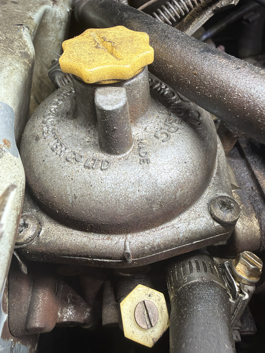
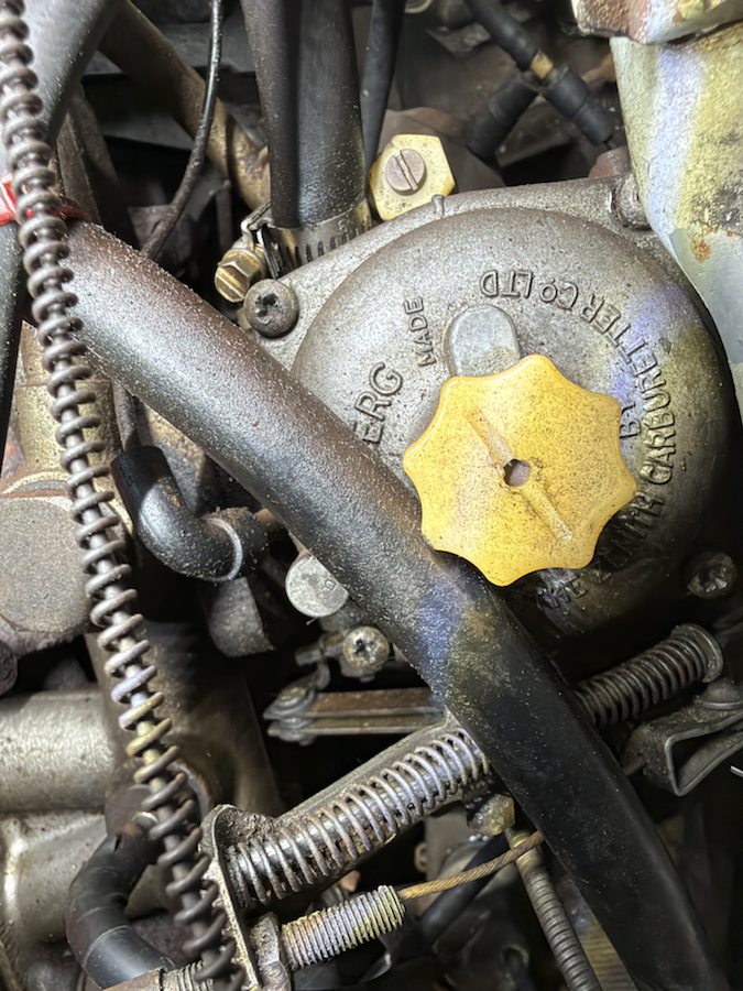
Tap a part in the model
Explore the assembly, one layer at a time
Open the interactive carburetor study and use Start study beneath the part details or the controls over the model. Six views separate the cap, visible screw group, cover, diaphragm, air valve and bowl. The order follows the factory exploded drawing as a visual explanation; it does not establish a safe removal path, full fastener count or service dimensions for this fitted unit.
Make the cover match your car
The CAD now has named fields for the widest round dome diameter, the flange outside width and length, and the yellow cap maximum diameter. Use the cover inspector and cap inspector: open Measurements and model details, choose directly measured on this car, record where the ruler or caliper touched, then export the measurement log. A separate owner STEP build can resize those outside shapes. The public CAD and hidden screw threads, internal clearances and removal path do not become verified through this measurement.
IMG_6958 has no ruler beside the cover. To record a photo estimate, take a new square-on photo with a ruler at the same depth; the photo worksheet keeps estimates separate from direct measurements.

What the new photo still leaves open
IMG_6958 also shows a pale hexagonal fitting below the cover, a hose and clamp, and nearby linkage hardware. Their identities, attachment points and full routing are not clear from this angle, so they are not represented as serviceable CAD parts. Photograph the carburetor from both sides and below, with its tag, before deciding what these pieces are or planning access around them.
Before a carburetor project
- Photograph the brass identification tag or stamped number close-up and include a wider image that shows where it sits on the fitted unit.
- Photograph both sides, the throttle and choke linkages, all fuel and vacuum hose connections, and the air-cleaner coupling before disconnecting anything.
- Measure the outside dome diameter, cover height and screw centers directly if an overhaul is planned. Record measurements with the corresponding photograph; the CAD's outside dimensions are provisional.
- Match the exact identified carburetor to the appropriate factory procedure and kit. The factory CD4T 150 side diagram, PDF p. 21 and CD4 exploded view, PDF p. 26 help identify parts but do not prove this car's exact variant.
- If dismantling is actually needed, document cover screw positions, diaphragm orientation, piston, spring, needle, float and gasket as removed. Keep small calibrated parts labeled and clean; use the full applicable instructions for service and reassembly.
