Identify the
round vacuum unit.
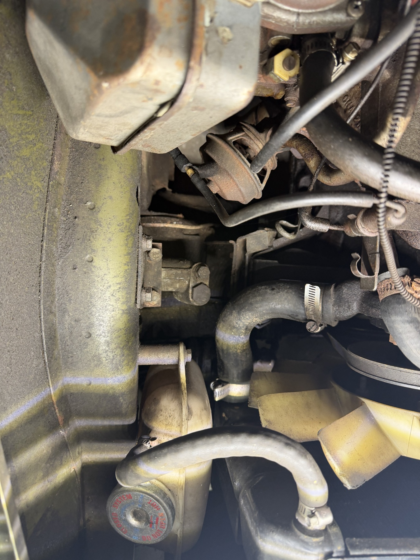
IMG_6887 shows a round diaphragm-like cover, open support cage and small hose connection between the cleaner and engine. Its appearance is consistent with the early exhaust gas recirculation (EGR) valve in the factory drawing. That is a candidate identification; the photo does not establish its number, complete connections or current fitted state.
Separate the catalog references
| Factory scope | Valve and connection references | What this establishes |
|---|---|---|
| USA/Canada “to 1977” · PDF p. 65, plate MB0704 ↗ | TKC1470 valve (37), 160108 locknut (38), UKC1813 manifold-to-valve pipe (34) | The drawing shows a round actuator/cage and its manifold connection. Its resemblance to the photographed unit does not identify the fitted number or dimensions. |
| 1977-on California · PDF p. 69 ↗ | TKC3306 valve; UKC7722 valve-to-elbow-adaptor pipe | A different catalog entry; this page says “illustration to follow” and supplies no silhouette for comparison. |
| 1977-on Federal/Canada · same list | TKC3320 valve; UKC7722 pipe | A separate market reference. The overlapping 1977 scope labels cannot select the correct branch for this car. |
Confirm the actual unit and its attachments. The vehicle year, round cover, small hose and catalog application alone cannot establish a fitted part number or justify a replacement order.
Resolve identity and connections first
- On the cold car, confirm whether the photographed unit is still fitted. Photograph the full unit, all accessible markings and a wider view tying it to the cleaner, carburetor and manifolds.
- Trace the metal body and any connected metal pipe by sight to their actual endpoints. Record which casting or bracket carries each connection. Keep an obscured endpoint marked unknown; do not assume the catalog pipe is present.
- Photograph the small hose connection and trace that hose separately. Record its actual destination and any intermediate fittings. It is not the large paired-wire inlet sleeve shown in IMG_6885.
- Transcribe only readable marks. Record partial characters separately from a confirmed maker/part number. Photograph the mounting interface and pipe fittings from both sides during planned access.
Geometry worksheet for future verification
Use a scale in each component's plane. Keep photo estimates separate from direct readings, and name the measuring faces. Do not remove this unit solely to obtain dimensions.
| Datum to record | Reading and source |
|---|---|
| Maximum round-cover outside diameter, including the rolled rim; identify the widest section | _____ mm · method/photo _____ |
| Cover face-to-face depth along its geometric axis; exclude hose noses and mounting body | _____ mm · faces _____ |
| Support/valve-body axial extent between named end faces | _____ mm · faces _____ |
| Each visible port or fitting: outside envelope, center and direction, connection type and actual mate | _____ · source _____ |
| Named cover front/rear extreme-plane centers, plus the mounting datum in one shared physical frame | _____ · frame _____ |
| Bracket/fastener arrangement and required surrounding space at the fitted adjustment/configuration | _____ · configuration _____ |
The downloadable v2 JSON is a blank evidence record: dimensions and coordinates start as null. A separate local tool can export a directly surveyed cover outside envelope. The record is not engine-builder input or a viewer mesh. Modeling the complete unit still requires a surveyed profile, connections and an engine-registered pose, with confirmed identity or an explicitly unidentified shape.
Build a measured cover envelope
Confirm a nominally round cover. Record its maximum diameter including the rim, excluding hose noses and the support body. Name the front and rear axial extreme planes; enter the center of each plane on the cover axis as cover_front_face_center_xyz_mm and cover_rear_face_center_xyz_mm. These are geometric datum centers, not arbitrary points on a curved face. Describe how you established both centers and independently measured the cover depth in the source note.
Set the evidence method to direct. Declare a physical origin, positive X/Y/Z directions, installed or bench configuration, and confirm a right-handed frame with perpendicular unit axes. All points must share that frame. Preserve old v1 main-axis readings: they may describe the body rather than these cover planes and cannot be automatically relabeled.
From the CAD source directory, using a Python environment with CadQuery installed:
python build_round_cover_survey.py --survey owner-round-unit.json --output-dir owner-round-cover --axial-comparison-limit-mm YOUR_LIMITReplace YOUR_LIMIT with your explicit comparison limit in millimeters. The tool compares the face-center span with independently measured depth and rejects disagreement beyond that limit. It does not move measured points to reconcile the readings. Supported input ranges are diameter 20–150 mm, depth/span 2–100 mm, coordinates ±3000 mm and comparison limit 0–10 mm; these are tool limits, not fitted dimensions or factory tolerances.
The outputs are round-cover-outside-envelope.step and an evidence report, round-cover-survey.json. The solid cylinder uses the maximum diameter and measured face centers; its flat end caps bound the axial extent rather than reproduce a domed face. It overestimates material in curved and hollow regions. Support body, cage, ports, threads and mounting hardware remain unmodeled. Other raw evidence is retained without geometry validation. Neither a valve identity nor an engine transform, contact, access or removal path follows from this envelope. The frame declaration itself does not independently verify the physical survey.
Compare a measured pose with the engine CAD
A separate registration tool can compare at least four directly surveyed fixed datums with explicitly identified references in one exact CAD model file. The first three pairs define a rigid transform; additional pairs test it without changing that pose. At least one check must lie outside both registration triangle planes. Keep target CAD coordinates distinct from measured car coordinates, and preserve the cover survey's physical frame and installed configuration.
Use the blank registration record and follow the CAD source instructions for datum selection, model fingerprinting, conditioning limits and export commands. An accepted comparison exports a cover envelope in the named CAD frame; disagreement beyond your entered limit exports a diagnostic report without a STEP. This is agreement with model references, whose geometry may still be provisional. It does not establish the unit's identity, complete shape, car fit or replacement access.
The exterior is now modeled
The whole-car model now includes the previously omitted round unit and local rigid-pipe architecture. Existing IMG_6887 and supplied IMG_7042 were reconciled before modeling. No new capture or direct owner dimension is applied. The early Federal EGR arrangement remains a candidate identification, without a fitted part number or verified operating state.
Body, actuator and pipe are separate references
The estimated exterior separates the body/pipe port, mount locknut, open cage/stem cue, shallow cover/rim, small hose spigot and untraced control hose. A rigid-pipe comparison has a bored banjo eye, separate union nut/olive, smooth bolt and two washers. Factory p. 65 supplies those comparison roles; the photographs do not establish the hidden manifold joint or complete small-hose route.
The four cage supports, 64 mm rim envelope, axis, tilt, mounting station, pipe curve, bores, socket, sections and hardware are all estimates. The cover is an exterior shell; no hidden diaphragm, return spring, pintle/seat, calibrated orifice, complete gas network or working banjo bolt is reconstructed. Later TKC3306/TKC3320/UKC7722 entries remain separate unselected branches.
The valve-body comparison overlaps the unchanged exhaust-manifold envelope by about 1207.8 mm³. The rigid pipe/eye overlaps the current carburetor envelope by about 1336.8 mm³ and inlet manifold by about 232.1 mm³. The cover has no overlap with the sampled carburetor, cleaner or manifold source solids. These are static reconstruction results, not fitted interference, sealing or operating-clearance findings.
The existing carburetor/manifold comparison separately reports a -20 mm axial face difference and -12 mm manifold-to-carburetor port-center Y difference. The new exterior does not resolve that registration conflict; no stud/gasket/heatshield stack is forced across it. Existing castings and cleaner are unchanged, and no hidden hole is drilled to manufacture a fitted joint.
Inspection and replacement limits
Use the links to distinguish cover/cage access, the local pipe union, banjo/washer interfaces and the small hose boundary. Keep the cleaner, carburetor and manifolds visible when assessing the source obstacles. All new parts share the engine’s display translation plus illustrative separation offsets. This is not a verified service assembly, release order or pipe withdrawal direction.
No fitted dimensions, identity, thread, sealing, tool size, tightening value, function test, thermal clearance or replacement/removal path is established. The existing worksheets above remain available for future evidence verification; this modeling pass requests no repeat captures.
Ten source groups / eighteen valid solids now supplement the model. Checks cover valid solids and STEP round-trip, open external banjo/union/spigot passages, the declared local pipe socket, metric placement and picking, isolation and illustrative movement. They do not verify the fitted car.