The fitted distributor.
Which version is it?
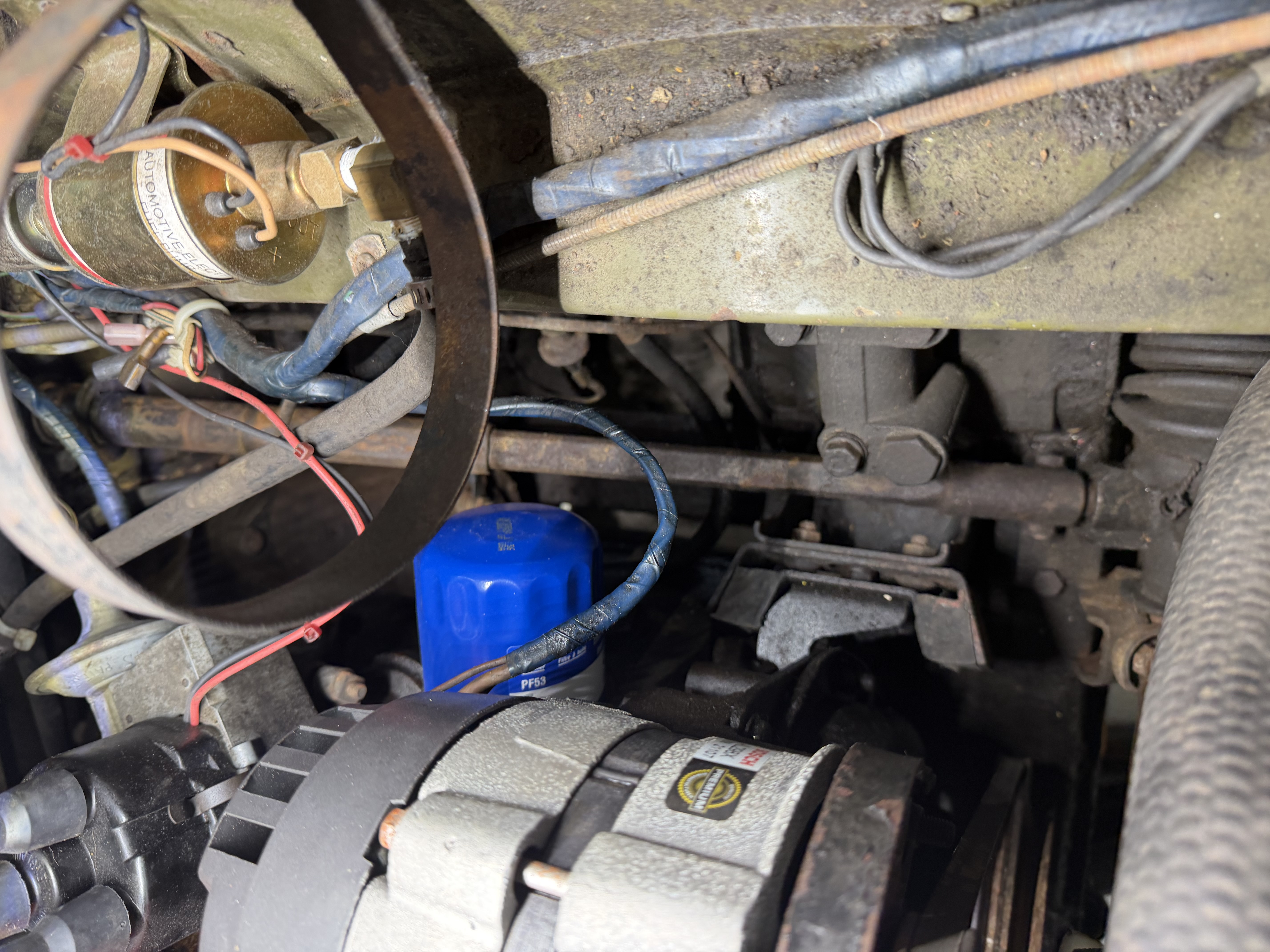
The latest owner photographs show a black cap with four plug-lead positions and a center coil-lead position, rectangular side housing, metal vacuum capsule, retaining clip and electrical leads. That combination resembles the body-mounted Lucas Opus electronic distributor shown in the Midget 1500 catalog. A photo of the distributor number is still needed before choosing its cap, rotor, vacuum unit, amplifier or service procedure.
The Moss Sprite/Midget catalog, printed p. 75 lists Lucas Opus distributor 41593 for 1975 and later remote-amplifier C.E.I. replacement 41804. It says to order by distributor number because components differ. The side-mounted housing in these photos favors the integral-amplifier layout, but does not prove that this car has a 41593 unit or that its electronics are original.
Compare the owner photos
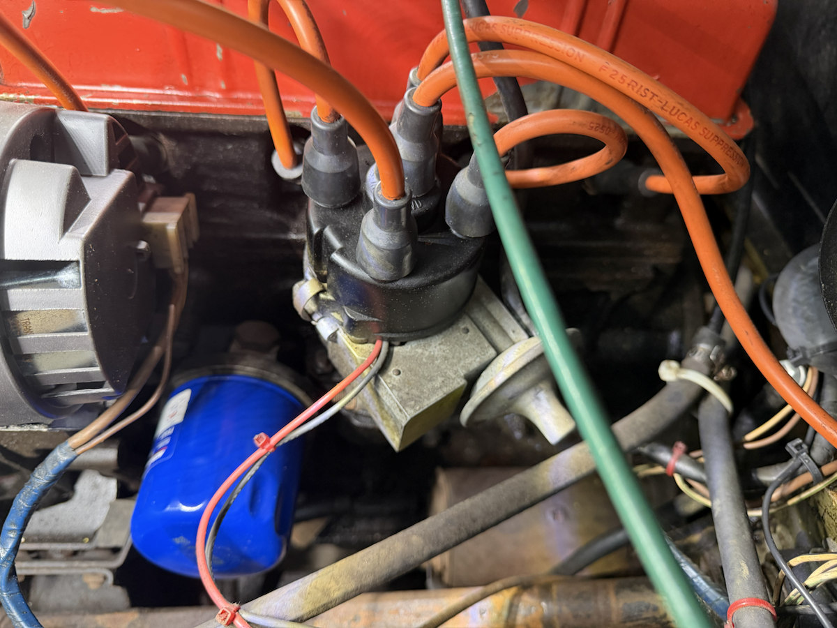
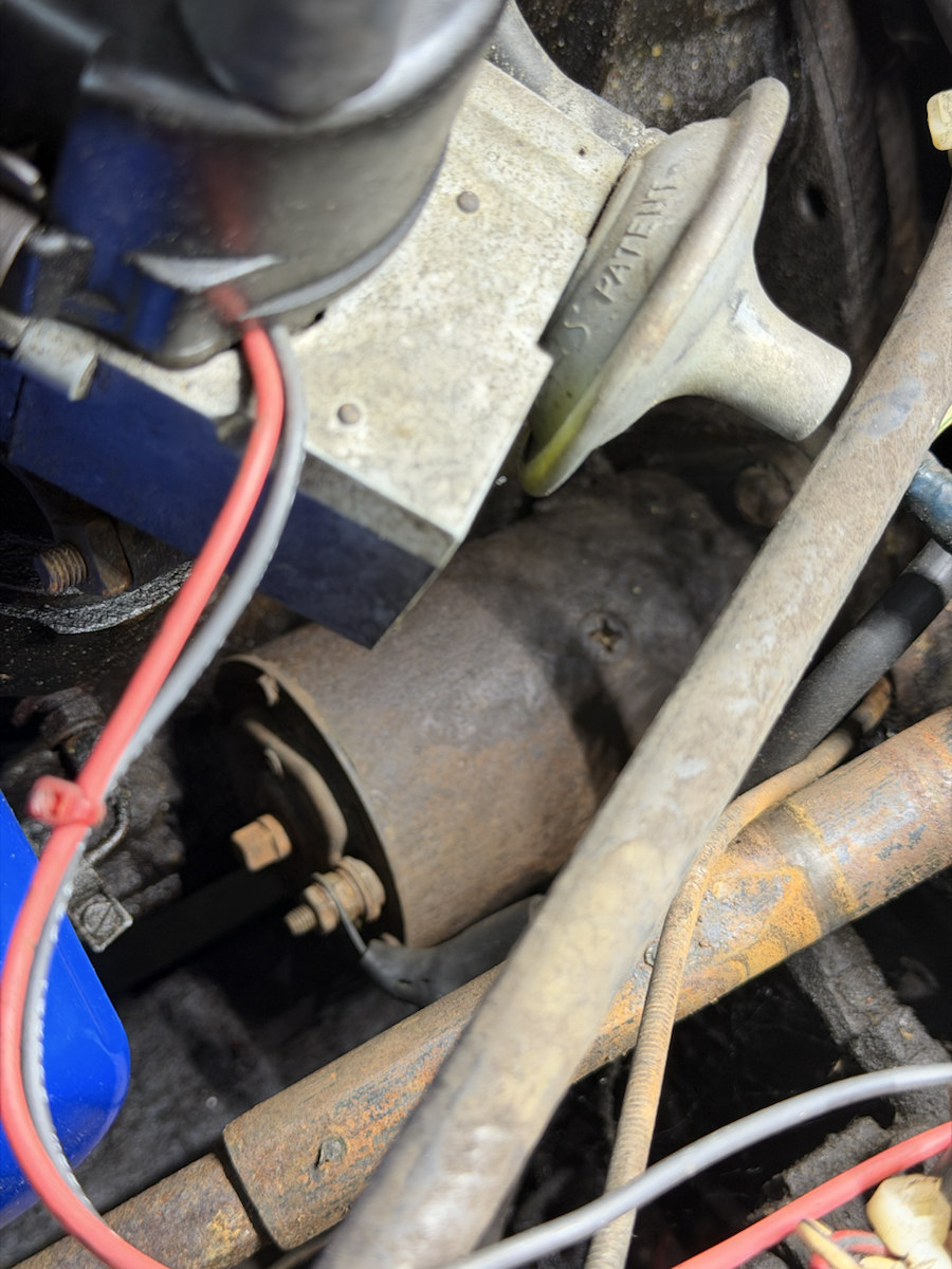
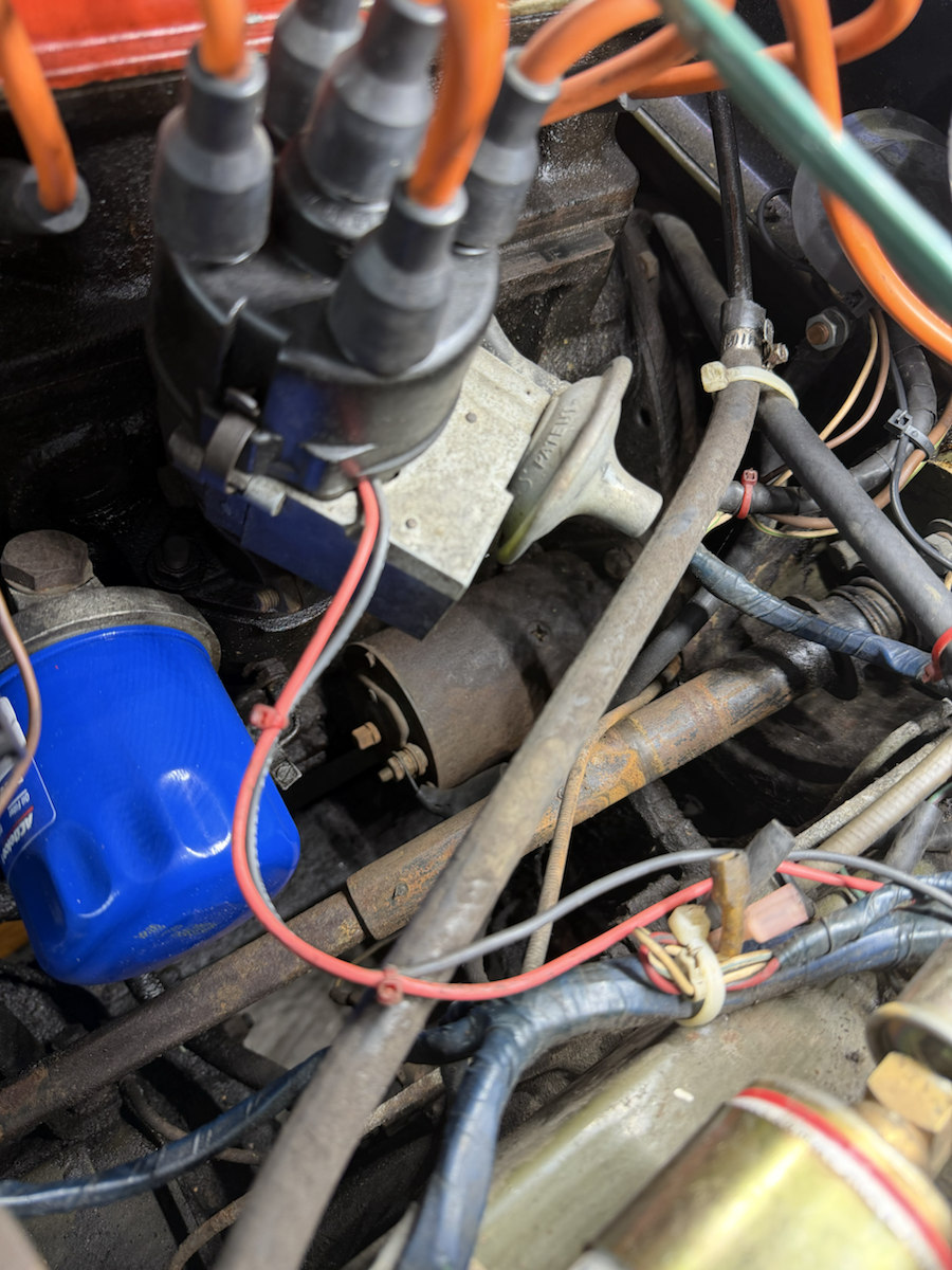
Inspect the cap and body separately
The CAD now separates the five-tower cap from the metal body at the existing study seam. IMG_6967 establishes the visible cap/body division and retaining clip; the split preserves all prior surfaces, dimensions and positions. Select either part to compare the joint, or use Show this CAD part alone to inspect the cap envelope. Its interior is still solid study geometry: rotor, contacts, locating rim, clip release and lead disconnection are not reconstructed. This selection split does not establish an opening motion or removal clearance.
Earlier dimensions under the original distributor key covered both cap and body. They remain in the log; the body inspector leaves its new inputs empty until the endpoints and source note are reviewed. Saving reviewed body-only dimensions retains the original record as unapplied source history. Cap-only readings have a separate key. Neither set currently changes an owner STEP.
Use the correct branch of the parts catalog
| Item | Documented comparison | What this car still needs |
|---|---|---|
| 1975 original type | Moss lists body-mounted Lucas Opus 41593. | Find and photograph the stamped distributor number on the fitted body. A matching appearance is not enough. |
| Later replacement | Moss lists remote-amplifier C.E.I. 41804 as the 1975 replacement. | Trace the actual module and wiring. A remote unit would change the parts and test path. |
| Vacuum capsule | Moss lists vacuum unit 142-890 for Opus numbers 41593 and 41656; other numbers use different units. | Read the distributor number and inspect the hose and capsule before buying. Do not select by the car's nominal year alone. |
| Cap and internal pieces | The Opus plate separates cap, rotor, timing rotor, anti-flash cover, O-ring and drive resistor. | Photograph these only during a planned inspection, preserving cap orientation, lead order and small hardware. Internal condition is not visible now. |
| Idle timing reference | The 1975 factory tuning table gives 2° ATDC stroboscopic at 800 rpm, consistent with the under-bonnet label. | Identify the fitted distributor and read the full applicable procedure before setting timing. The printed figure is not a measurement of the current engine. |
Capture a parts-order record
- With the engine off, photograph the cap and all five lead positions, then trace each of the four plug leads to its cylinder. Record which wire feeds the center of the cap.
- Photograph the distributor's metal body from all accessible sides with the cap in place. Find the Lucas type and five-digit number; keep uncertain digits as “?”.
- Photograph the side housing, its retaining screws, connector and every wire where it enters or leaves. Note whether any separate amplifier is mounted elsewhere.
- Photograph the vacuum capsule and trace its small hose to its other end without disconnecting it. Record any number or stamp on the capsule.
- Record the cap-clip positions and distributor clamp/adjuster location. Mark the present body position before any planned removal.
- Compare the actual distributor number with the catalog branch, then choose a parts list and service instructions for that number. Record direct measurements if a replacement must clear nearby hoses or filter hardware.
Pedestal, clamp and lower drive
The model now separates the distributor pedestal, split collar and transverse fixing from the two vertical base retaining sets, lower shank, unloaded oil seal and drive gear/shaft/pin. Existing distributor, cap, amplifier, filter, alternator and engine meshes retain their source positions. The added interfaces are estimated reference geometry; no hidden block seat or hole is cut to force a fit.
Factory parts p.59 supplies 121530 pedestal, two retaining nuts/washers, a transverse clamp bolt/nut/washer and separate 104860 gear, 104861 shaft and 500974 pin. Its .006-inch (0.1524 mm) and .020-inch (0.508 mm) gasket alternatives stay distinct. The displayed single .006-inch gasket is unselected; it does not establish fitted stack or end float. Factory p.173 preserves USA/Canada distributor branches, RTC1773 clamping-plate and 27H6547 seal roles. The relationship of that plate to this fitted pedestal is unresolved; no additional fitted plate is invented.
IMG_6966/6967/6970 and supplied IMG_7039/7041 establish neighboring filter, alternator, distributor and wiring context. They do not calibrate hidden mounting axes. Every new profile, hole, threadless fastener, shank/seal boundary and station is estimated. The drive has no teeth or selected slot phase, and its lower shaft ends openly without a forced camshaft/oil-pump join.
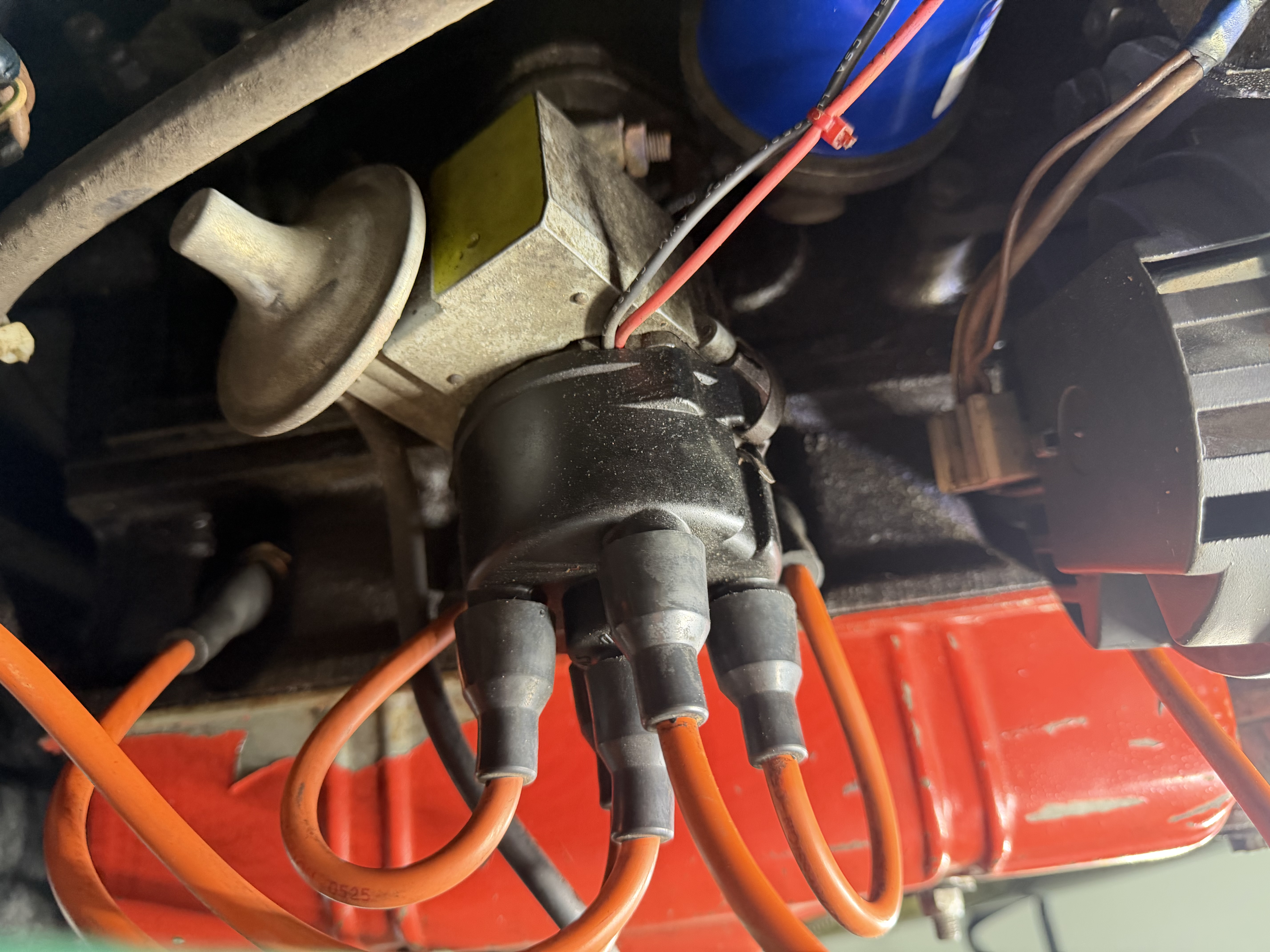
Limited source-solid contact sample: None in this limited sample. These are reconstruction discrepancies, not evidence of actual interference or clearance. The retained source frames leave pedestal-to-block 5.5919 mm, smooth gear-to-camshaft 14.1666 mm and shaft-to-pump-body 171.5472 mm minimum geometric separations. These are unregistered reconstruction gaps, not installed clearances or engagement settings. Common engine/body registration, actual distributor identity, timing phase, loaded seal/clamp fit and access remain unverified.