A separate lever.
A visible joint.
The old rod attached to the swivel-carrier representation is replaced by a separate offset steering lever, two securing screw envelopes and a common lock tab. A tapered-eye/stud comparison, separate washer/nut and hollow dust gaiter expose the connection below the retained outer ball center.
What supports the change
Factory p. 140 separates later AHA9957 RH/AHA9958 LH steering levers, one 53K1370 short screw and one ATA4132 long screw per side, and a common 2K5377 lock tab. Earlier BTA648/649 arms remain a separate branch. The drawing supports separate parts and connection roles; it does not supply this model’s contours, hole map, blind depths or installed coordinates.
The later rack drawing, p. 133, separates BHA5141 sockets, 143992 gaiters, washers and nuts. The supplier’s own GSJ158 photo supports a tapered stud, dust bell and locking-nut arrangement and lists Midget 1500 application. Its current replacement nut is advertised as M10 × 1.0. That supplier comparison is not equated to factory GHF223 or this car’s fitted thread; the new terminal/nut surfaces remain smooth estimates.
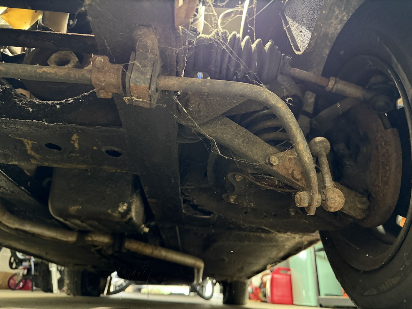
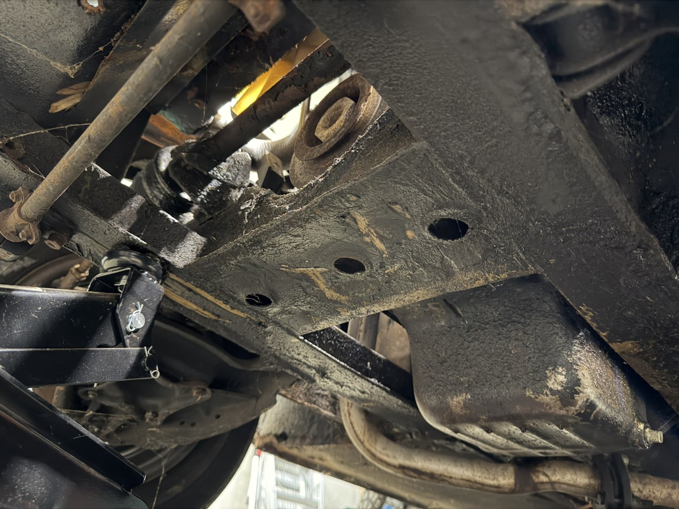
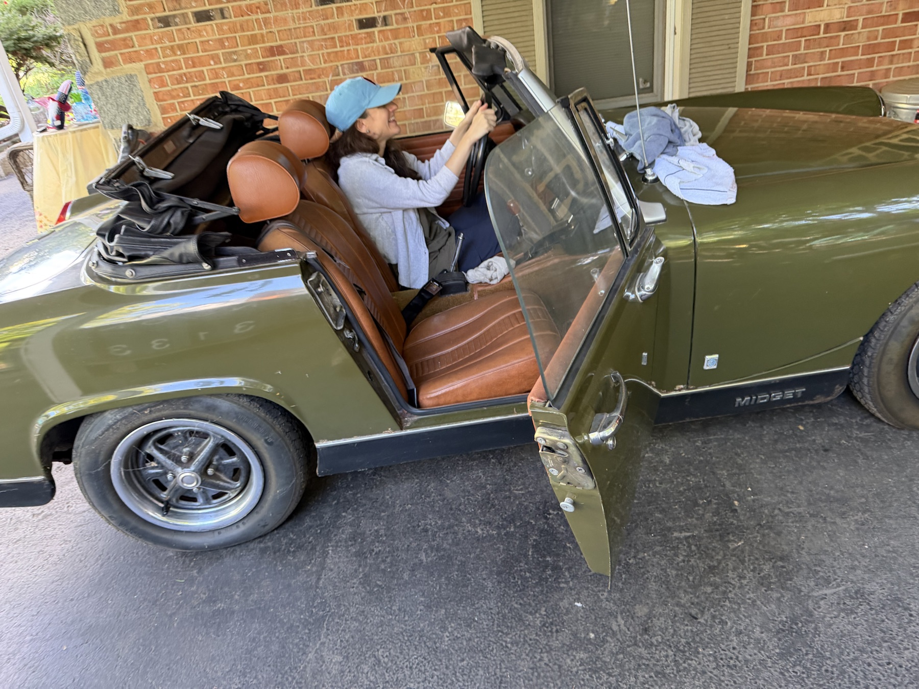
Existing owner IMG_6914 supplies front-corner context, including the rack/rod area among the spring, anti-roll bar and wheel. IMG_6919 and IMG_6341 supply underside/cabin context. These views do not calibrate the hidden lever mounting or taper. No direct owner dimensions are applied and no repeat capture is requested.
Construction choices stay explicit
| Interface | Estimated model geometry |
|---|---|
| Carrier / lever foot | A 12 mm foot sits on the old spindle-base inboard face at X magnitude .506 body units. Two X-axis holes, separated by 48 mm vertically, share the tab, lever and estimated blind carrier bores. Depths are 14/20 mm; these are not factory drilling dimensions, threads or surveyed bolt centers. |
| Offset lever / eye | A swept oval blade connects the mounting foot to a 14 mm-thick vertical eye. Ball center, rod/socket axes and eye plan position stay at the old reference stations. The new eye center lies 26 mm below the former rod endpoint. This is a construction relocation, not a measured steering-arm height or alignment result. |
| Taper / terminal | Eye radii 6.3–7.3 mm and stud radii 6.2–7.2 mm across the estimated 14 mm stack expose the taper relationship. The 0.1 mm radial difference is construction separation only. Smooth terminal radius 5.5 mm, washer and nut sections do not identify a fitted metric/imperial thread or verify locking. |
| Dust bell / lock tab | The hollow gaiter and small tab lips show separate component ownership. Loaded seal contact, material, compression, actual tab folds and engagement are unknown. The generic right lever is mirrored from the left; actual handed forging differences are not reconstructed. |
Open passages and zero sampled solid overlap establish consistency between these reference parts only. They do not establish taper seating, clamp preload, blind thread engagement, body strength, articulation, toe, caster, Ackermann geometry or operating travel. The rod/socket axis and spindle/kingpin/hub stations remain estimated and unregistered to a common survey of the car.
Inspect the replacement boundaries
Selection and isolation can now distinguish the body of the lever from the carrier, its two securing screws, tab, ball stud, under-eye retainers and dust cover. The lever shares the carrier’s general display translation; its fasteners and joint parts separate illustratively. No displayed direction is a verified installed withdrawal or release path.
A matching later factory service procedure and this car’s actual joint/hardware state are still required to verify support, release order, separator access, refitting and alignment checks. The earlier AKD1775 rack procedure remains unapplied to this later installation. No torque, safe support arrangement or verified removal path is inferred from the parts drawing.
Native exports and checks
The new asset has twelve source meshes and sixteen valid STEP solids. Rebuilt carrier geometry removes the old rods and adds the shared blind holes; its other sixteen source meshes remain identical. Rack export now omits the two superseded cylindrical stud/retainer meshes; all twenty-three retained meshes are identical. Build the lever asset before front-kingpin; the carrier reads its hole map. Browser checks cover placement/picking, passages with neighboring material, fixing occupancy and inspection ownership. None verifies fitted clearance or service readiness.