Follow the rack
to its supports.
The coarse rack and column shapes are replaced by a hollow case, pinion junction, smooth bar and shaft, hollow outer sleeve, split coupling, bellows, separate inner and outer joint boundaries, handed support brackets and front clamp caps.
Factory configuration stays separate from the car
Factory p. 133 separates later AHA9955 LHD / AHA9956 RHD racks, different pinion-side/opposite bellows, inner ball joints, BHA5141 outer sockets, AHA9959/60 handed mounting brackets and two AHA9961 clamps. Six mounting screws are listed. This model follows those exterior roles and count; its symmetric generic bellows, folds, hole positions and fixing-axis/length assignments are construction choices. Earlier p. 131–132 rack internals and bracket/seating parts are not silently substituted.
Factory p. 137 lists CHA341 North American collapsible column from GAN6-154101. That supports configuration only. The hollow sleeve and smooth shaft do not model its energy absorption, bearings, steering lock or working collapse mechanism. Existing fascia support, body flange, seal and aperture are retained on their previous axis.
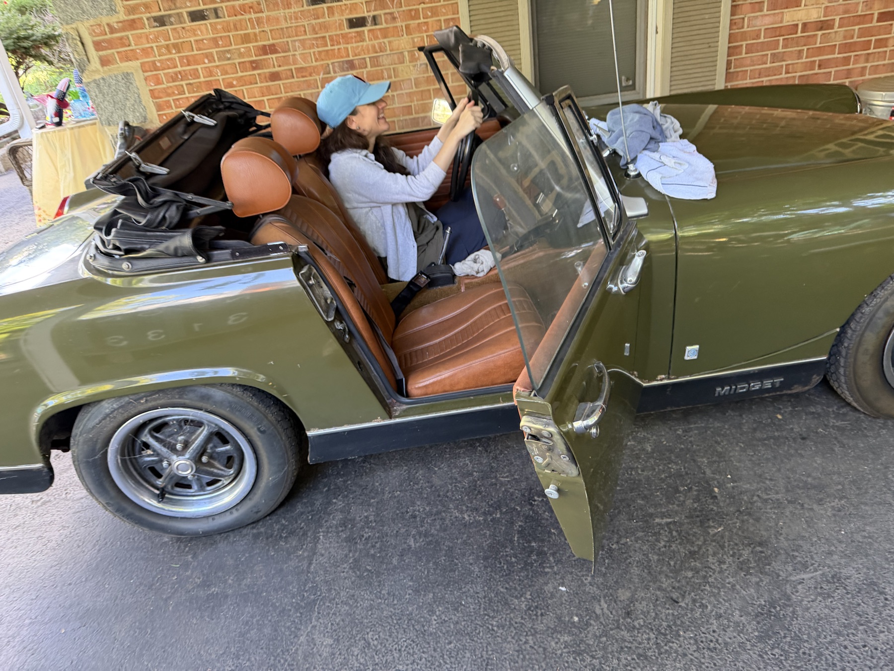
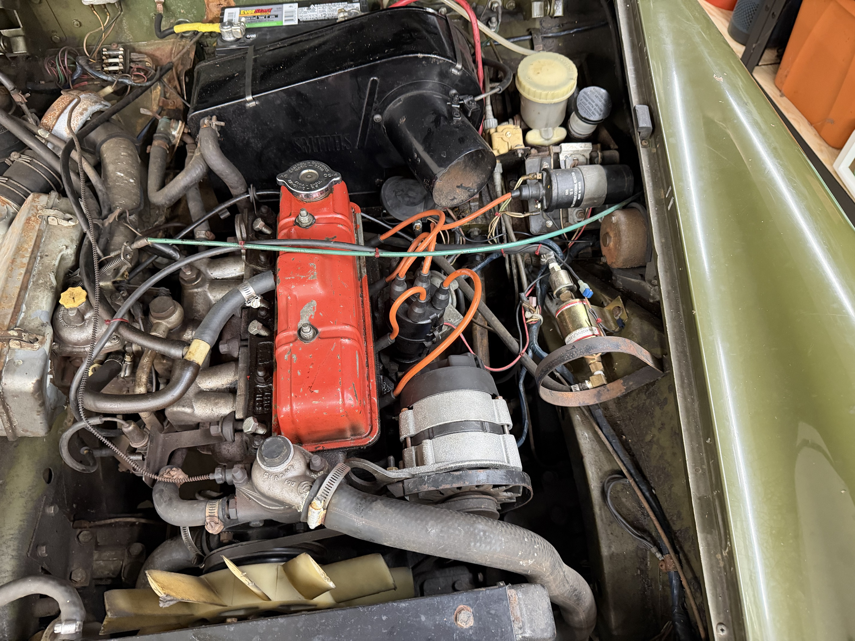
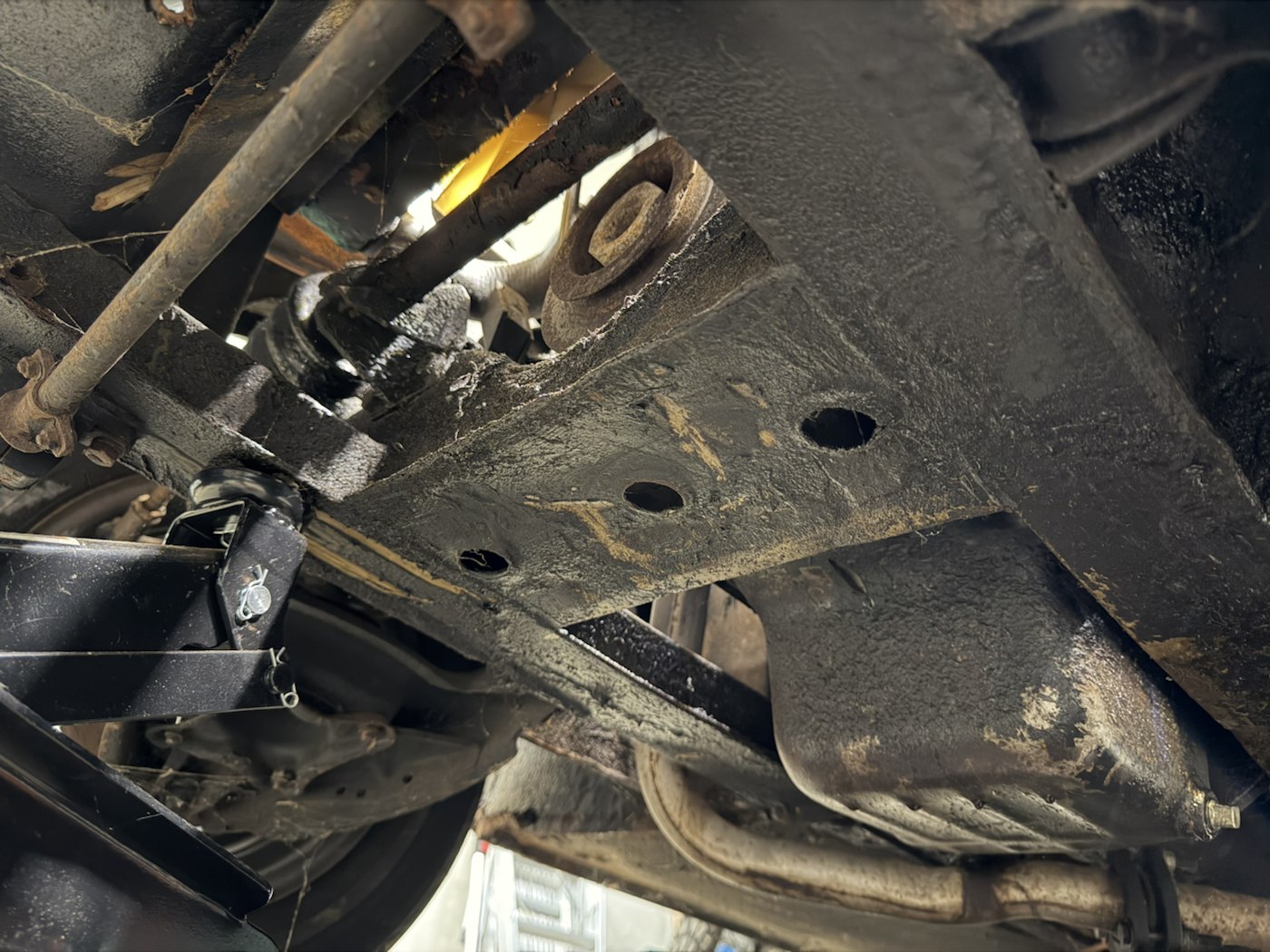
Owner IMG_6341 establishes left-hand-drive cabin context; IMG_6855 supplies bay surroundings and IMG_6919 front underside context. These views do not identify the rack or calibrate its hidden geometry. No direct owner dimensions are applied here; no repeated capture is requested.
What changed geometrically
| Relationship | Reference construction and limit |
|---|---|
| Case and smooth rack bar | The old 71.12 mm diameter solid case becomes a 28 mm outside / 22 mm inside diameter tube. These are estimates informed by unscaled drawing proportions, not factory or owner dimensions. A separate smooth bar has no teeth, pinion engagement or working travel. |
| Pinion and column | A hollow junction/oblique neck reaches the retained lower pinion point along the revised estimated column axis. The input shaft and shortened inner-column end meet inside a split sleeve with a transverse external fixing. No spline, shaft groove, locking or contact fit is verified. Housing/case separation is a visualization boundary, not a detachable casting joint. |
| Joints and protection | Inner cups, smooth ball/rod references, outer sockets/studs, hollow seven-convolution bellows and clip bands replace solid boots and spheres. Actual bellows variants, thread adjustment, joint preload, seal and taper fit remain unknown. |
| Body supports | Rear cradle/web/foot references meet the generic body-pad tops. The left support and pad move from X=.27 to .16 body units (93.1333 mm inward) to separate them from the estimated pinion envelope; this is a construction relocation, not a fitted station or clearance. Both pad incline angles now follow their actual endpoint vectors. Front caps share four construction passages with the brackets; one top fixing per side shares an estimated pad bore. No actual body hole map, captive retention, pad identity or loaded support is verified. |
The steering-lever study replaces the integral carrier rods and old cylindrical stud/retainer meshes with separate levers, two-screw/tab mounts, tapered eyes/studs, retainers and hollow dust bells. New eyes lie 26 mm below retained ball centers as an explicit construction relocation. All fitted taper, mount height, hardware, alignment and travel remain unverified.
Sampled CAD intersections are zero between the final supports/fixings and pinion housing, and between the local inner cup/rod, outer socket/stud and bellows/rod references. These are source-solid checks, not fitted clearance results.
Raised plunger housing beside the filter
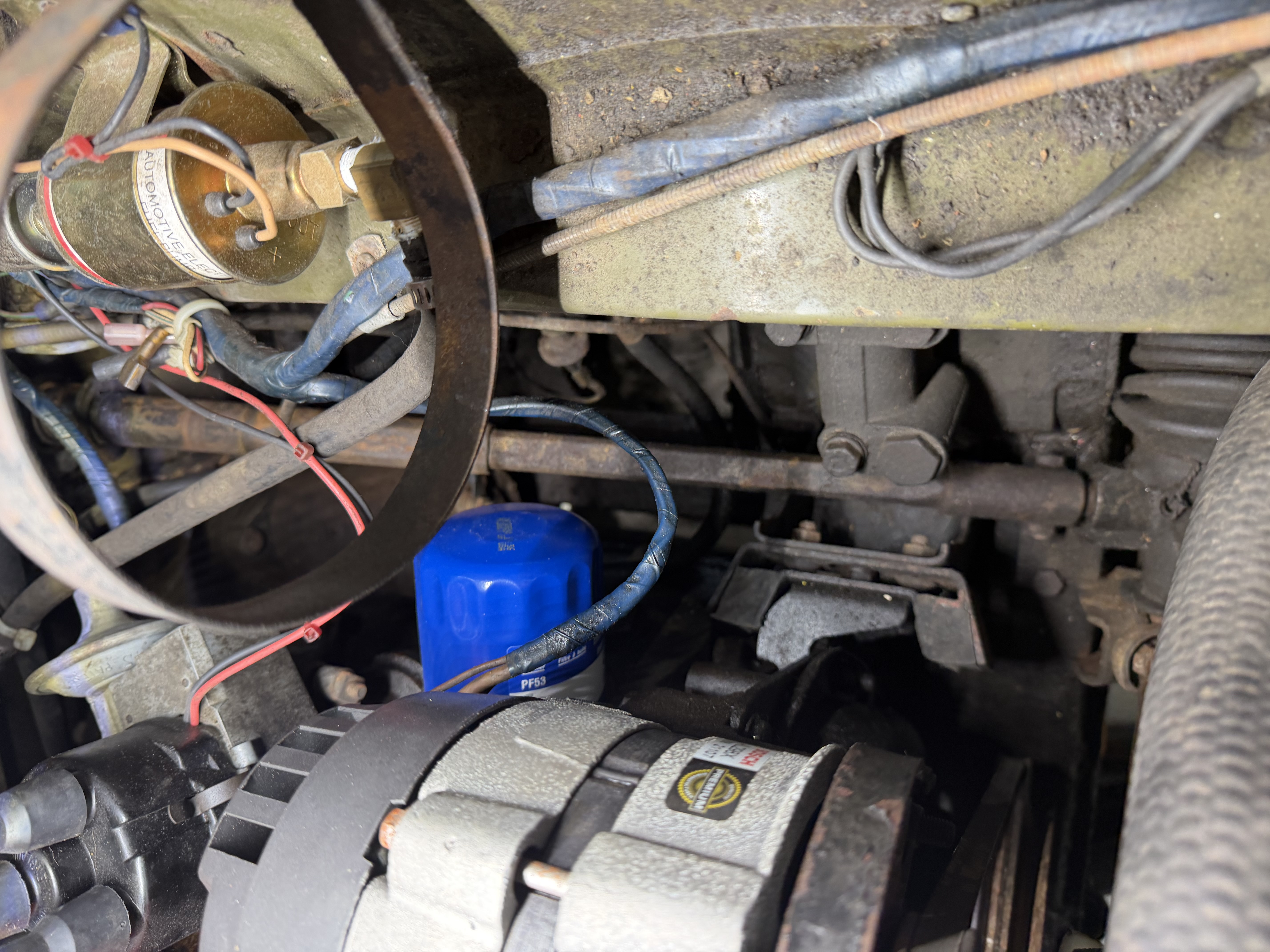
IMG_7041 and factory plate 133 support the cast-junction/raised top-cap architecture absent from the previous spherical housing cue. The new lofted junction, hollow tower and separate smooth plug/hex cap retain the rack centerline, column axis, brackets and surrounding engine geometry. All new sections and stations remain drawing estimates; the photograph is not used to infer a fitted filter/rack clearance or move the engine.
The factory lists 37H7336 cap, 120946 plunger, 126765 spring and separate shim roles. These are catalog comparisons, not fitted identities. The model exposes the cap boundary without constructing hidden spring/plunger internals, threads, a seal, a preload value or an adjustment procedure. The cap's upward inspection offset does not establish a safe release sequence or actual access past the mount, filter and alternator.
Wheel, body seal and lower shaft now share one axis
IMG_6341 supports a wheel set back into the cabin. The earlier model put its center only about 46 mm behind the fascia face, with the thick outer sleeve extending about 401 mm forward of the reference body-seal plane. The wheel center now moves 245.5333 mm rearward as an explicit construction estimate. The wheel plane, shaft, pinion entry/clamp, upper support, body flange/seal and bulkhead aperture follow the same revised axis. The thick sleeve ends at that reference body crossing; an exposed lower shaft continues toward the rack.
Factory pp. 137–138 supplies the column/flange/seal/lower-shaft architecture, not the new coordinates, sleeve length or an identification of this car’s column. The rack centerline, brackets, track datums, engine and coil are retained. The photo supplies qualitative cabin context; center, angle, sections, supports and body opening remain uncalibrated estimates. A matching axis and zero sampled overlap do not prove fitted alignment, collapse behavior, loaded support, running clearance or removal access.
The source conflict remains unresolved after the later cover and column-exterior revisions. The current unchanged shaft intersects the pedal housing by3735.583227 mm³ and cover by2697.234131 mm³, with a further cover-seal contact. These are source-model discrepancies, not measured contact on the car. The new lattice jacket and end collar have their own recorded contacts; no shaft kink, body notch or forced relocation is introduced. See the current contact report rather than earlier historical sleeve/cover figures.
Inspect the revised column in the whole car ↗ · Inspect the wheel ↗
The North American column exterior
The plain outer tube now has the architecture shown in factory plates137–138: an open lattice lower jacket, closed upper jacket, end housings and a separate steering-lock/switch assembly. The whole-car overlay retains the original smooth inner shaft and the same wheel, body-crossing and rack axes. It adds six native source groups comprising eleven valid solids; it does not simulate collapse or lock operation.
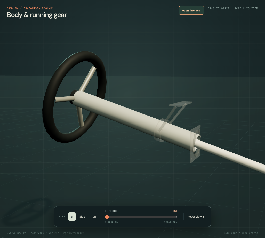
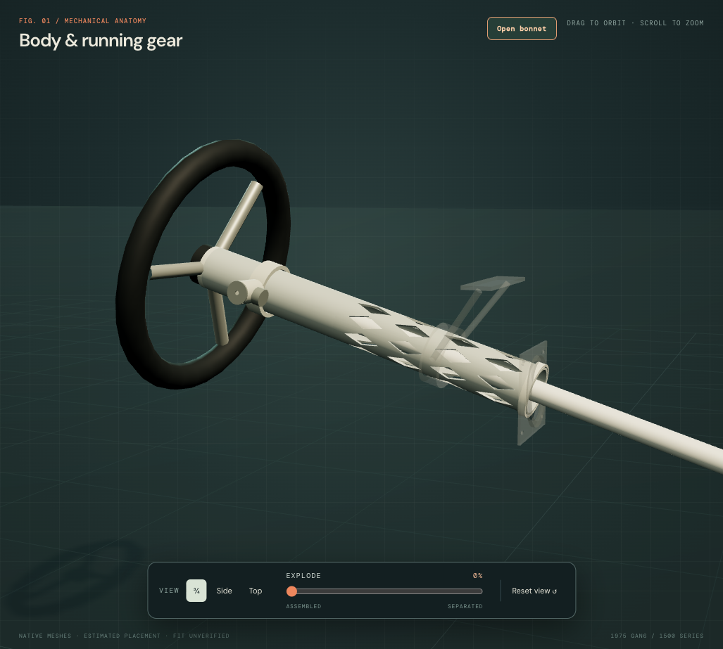
CHA341 and18G9119/BHA5292 are North American GAN6 configuration comparisons. Existing owner views do not identify these hidden fitted parts or supply dimensions. The old main jacket radius and axis remain; the55-percent lattice span,32 openings, end housings, inboard lock orientation, switch boundary and smooth shear-fixing roles are explicit drawing estimates. The one-millimetre clamp gap and half-millimetre face/switch gaps are inspection allowances, not fitted clearances.
What can be rehearsed
Select the column, lock, switch and fixing roles to distinguish their ownership and the surrounding fascia/body supports. Separation exposes reference boundaries. It does not establish a release sequence, switch wiring, key or lock compatibility, shear-bolt removal, collapsible-column handling, loaded support, tightening or an actual withdrawal path.
The mounting gap remains open
IMG_6341/6855/6962/6973/7040 and the factory exploded drawings do not supply calibrated common column/pedal mount coordinates or hidden housing dimensions. They cannot yet distinguish an incorrect column pose from an incorrect pedal/body reference. The unchanged shaft still crosses the housing and cover in the source model. The new collar also has small positive contacts with the existing flange, seal and bulkhead. All are recorded; neither the body opening nor the pedal box is altered to manufacture a fit.
Workshop use and procedure boundary
Select and isolate case, bracket, cap, fixing, bellows and joint groups to inspect their ownership and surrounding obstacles. Body brackets stay fixed in the separation display; other parts use illustrative translations. Those translations do not prescribe the release order or the direction in which the installed assembly can leave the car.
The available earlier AKD1775 steering section describes an earlier rack and column installation. It is not used here to certify a later GAN6 rack/column procedure, lubrication choice, preload, tightening figure or withdrawal path. A matching later factory procedure, fitted rack/column identity and registered obstacles remain required before replacement rehearsal can be called verified.
Model checks establish internal geometry only. No safe support/release sequence, actual bolt engagement, bearing or rack adjustment, loaded clamp function, fitted strength, collapse performance or final alignment has been established. The separate lever study now supplies an estimated arm/socket taper and fixing relationship. Evidence-supported installed obstacle registration remains unresolved.
Native exports
The original steering export contains23 metric source meshes in22 selectable groups. In the whole-car view, the new column source replaces only its plain outer sleeve; the original shaft remains. The separate column exterior export contains six source groups. Build it before front-structure when refreshing both; the latter reads the two declared pad-hole centers. The other thirteen front-structure meshes are retained exactly. Checks cover valid solids, STEP round-trip, cap/bracket and body/pad passages, separate fixing occupancy, hollow bellows/sleeve, native scale/picking and inspection ownership.
Cabin-height construction update
The coordinated fascia/column revision retains wheel X/Z and the lower pinion point, while deriving a lower wheel height from the revised face relief. The shaft, sleeve, pinion input direction, coupling, upper support and body flange/opening follow that axis; rack/track/mount centers stay. The approximately 87.5 mm wheel-height change is a drawing estimate, not a measured adjustment or steering recommendation. Selected native face/instrument intersections are absent, but six column/pedal source contacts remain. Fitted rake, ergonomics, collapse behavior, loaded support and removal paths remain unverified.
Exposed lower shaft and rack entry
The former source used one 27.093 mm-diameter cylinder from rack to wheel. IMG_7041 shows a visibly slimmer exposed shaft beside the fitted PF53 filter. The revised source uses a 16 mm estimated lower section, retaining the old hidden upper section and the complete straight axis, endpoints and body crossing. A body-plane diameter step is a construction boundary, not an observed telescoping joint or collapse mechanism.
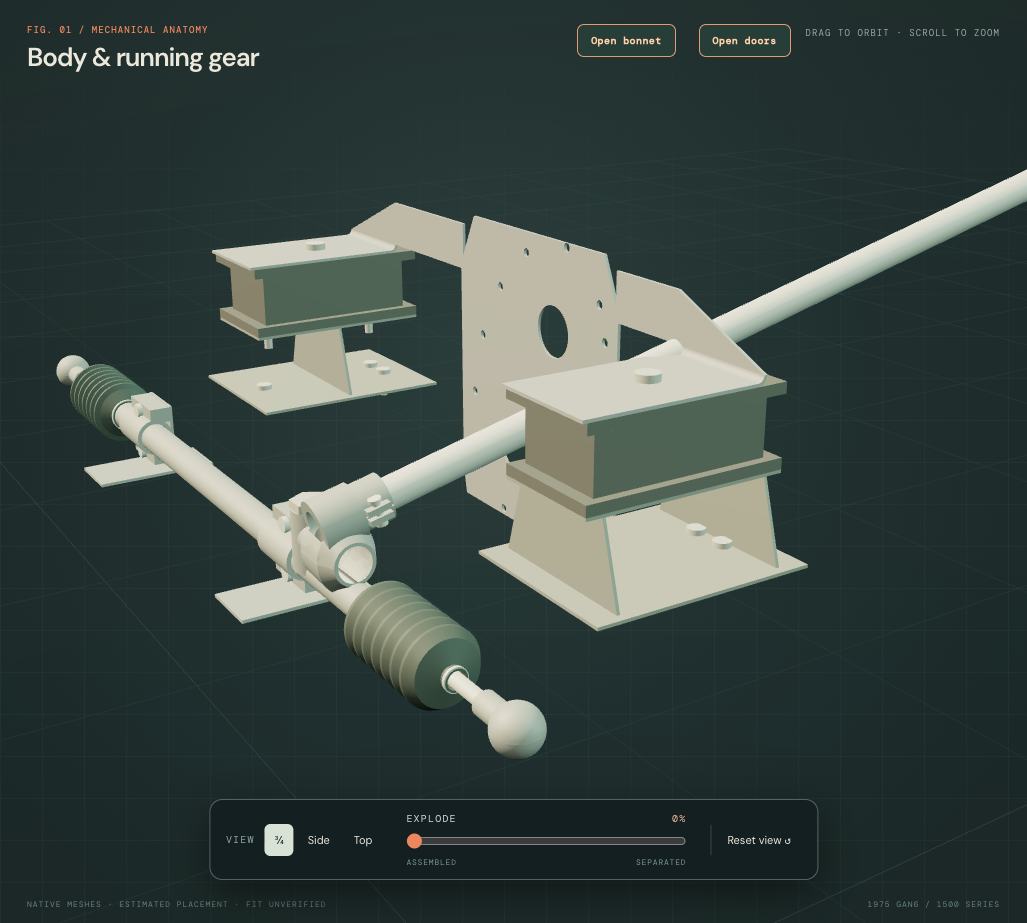
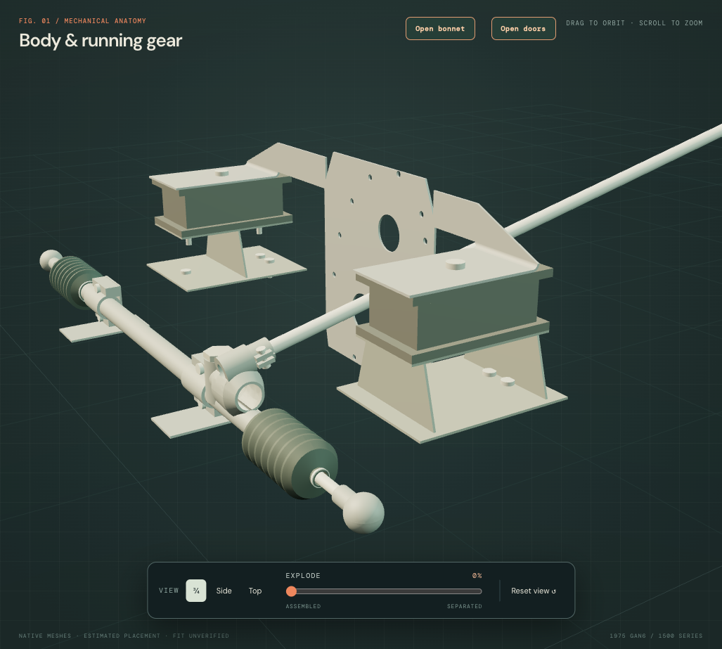
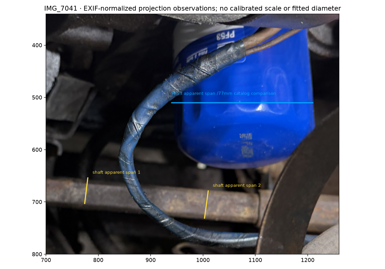
The PF53 catalog listing gives a 3 1/32-inch outside-diameter comparison (about 77 mm). The PF53 marking is visible owner evidence; its catalog size does not measure this canister or establish a shared scale for neighboring parts. Factory North American column plate p.137 distinguishes the exposed shaft and outer jacket, but supplies no diameter used here.
A matching smooth 16 mm input stub, 16.8 mm coupling bore, 28 mm coupling exterior and 34/17.6 mm neck outer/bore comparison replace the former bulky entry. Pinch-fixing position follows the smaller collar. All these sizes and display gaps are estimated; no spline count, fitted engagement, taper, thread, strength or working gear/collapse mechanism is established. The rack case, plunger/cap, tie rods, bellows, brackets and 20 source mesh groups stay. The outer column assembly, upper shaft, fascia, mount, engine/body and lower body/frame exports stay.
Registration remains open
The source shaft still overlaps the left mounting comparison by about 2,439 mm³ and the engine plate comparison by about 253 mm³. The former source values were about 7,863 and 1,252 mm³. These are static model discrepancies, not fitted interference or clearance measurements. No mount, column axis or body frame is moved to erase them. Zero local shaft/stub/collar contact only checks the smooth reference envelopes; it does not verify an assembled steering joint.
The official publication catalog identifies the 1975 North American manual as AKM3267. Its relevant full alignment/removal text remains unread here; the parts drawing and UK engine-mount illustration do not validate a North American steering procedure. Isolation and separation remain inspection illustrations, without safe release, support, adjustment or verified removal paths.