Beyond the
solid frame block.
Hollow rails, a formed crossmember with an rear/top mouth and front-face access holes, open spring pockets, upper seats, damper platforms and pickup ears now replace the old solid frame boxes and isolated spring discs. Separate buffer and unassigned rack-body pads add the neighboring interfaces.
Inspect the structure
Owner photos and manufacturer branches
IMG_6910 shows the upper opening and nearby front engine structure. IMG_6914 shows the broad underside member, suspension and anti-roll surroundings. IMG_6919 shows several underside openings and adjacent formed walls. These are shape/context observations; they supply no calibrated section, wall gauge, hole spacing, structural-condition survey or common engine/body frame.
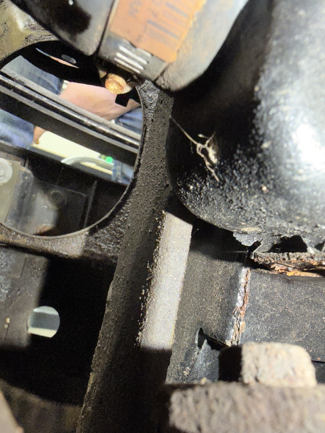
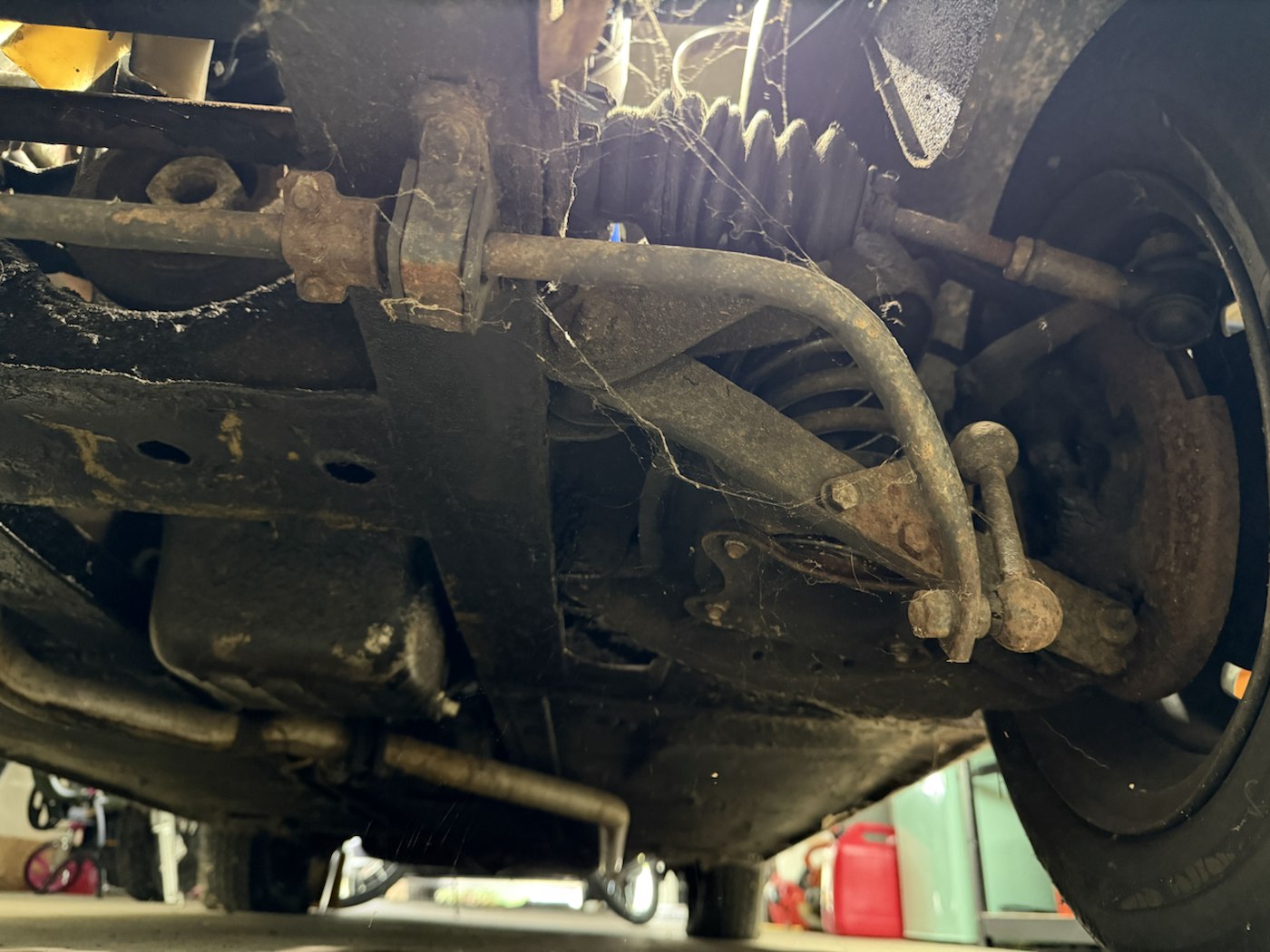
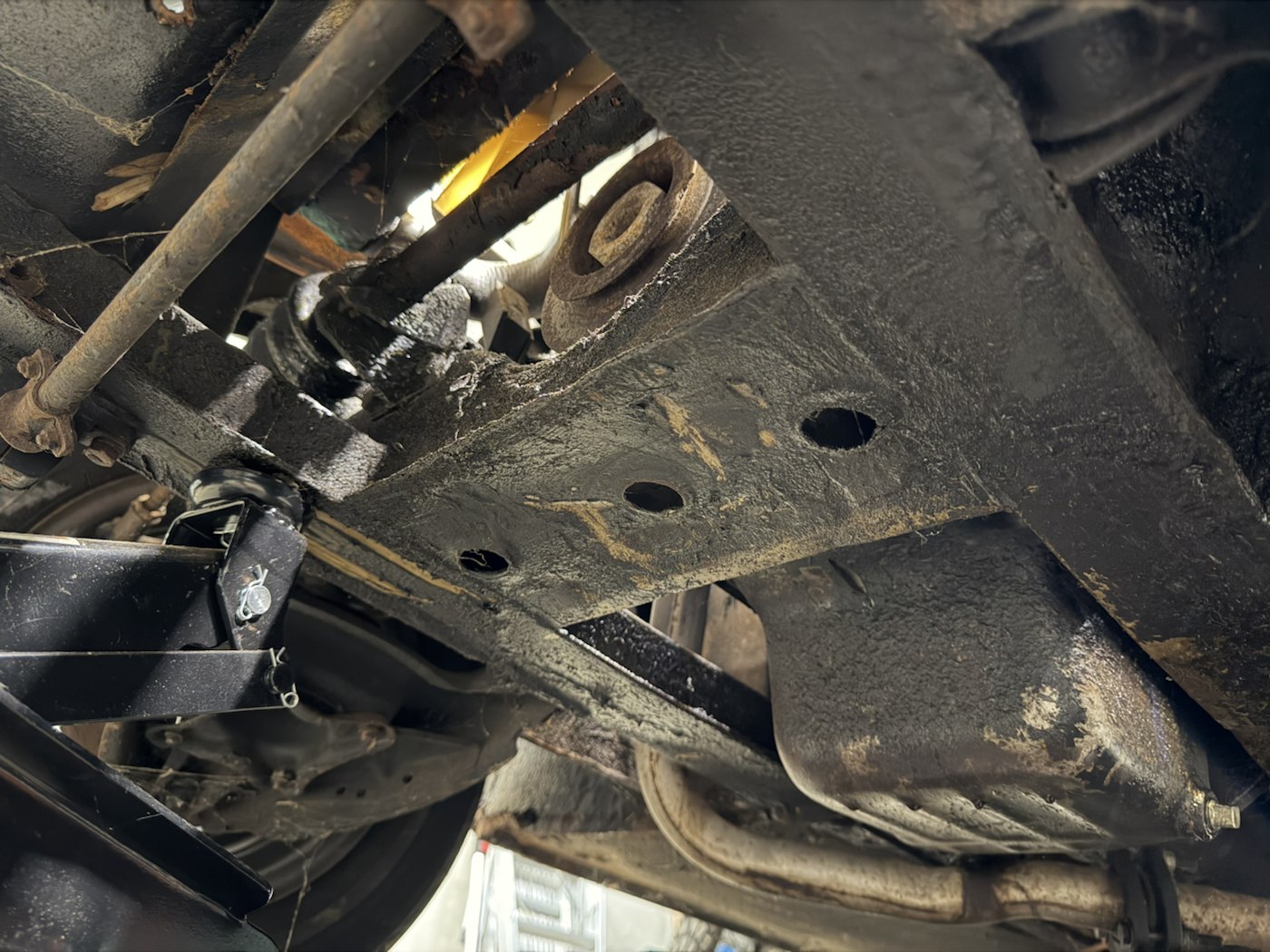
British Motor Heritage’s drawing and application table distinguish rubber-bumper CZJ676 underframe, BMH8030/31 side members and CZJ542/543 lower-link bracket applications from earlier body versions. They support assembly architecture, not this car’s fitted repair history or dimensions. BMH8007 rack mounting rail is listed for chrome-bumper bodies; the generic rack pads here are not assigned that part number.
Factory suspension plate, PDF p. 139 and p. 141 separate lower link/pins/bushes, dampers, springs, seats and buffers. Six damper fixings are a catalog count; the three modeled bore centers per platform are estimates. The new upper seat is a body reference, not a claim that the factory 21A137 lower spring seat belongs above the spring.
Retained references, new estimated surroundings
Rail outer sections and top/bottom stations are retained: the front engine-bracket base still approaches Y=.385 and the anti-roll body interface still approaches Y=.255 body units. Lower-link axis centers remain at X magnitude .36, Y=.27, Z=.98/1.42. Spring axes and former upper-seat bounds remain; damper support reaches the existing pad underside at Y=.6225, while generic rack pads approach the existing clamp lower face at Y=.35. These are existing drawing constraints, not measurements.
Open-ended rail cavities and 2.54 mm estimated walls replace filled blocks. The formed crossmember’s large upper opening and three lower holes are recognition geometry. Revised rail pockets and eight bored pickup ears now follow the separate inner-fulcrum comparison while retaining the old pivot centerlines; they do not identify actual body cutouts or a repair bracket profile. The inboard damper webs and open-outboard spring pockets supply previously missing body obstacles without changing the running gear pose.
Profiles, inclines, wall sections, apertures, holes, weld seams, buffer shape and all joints remain estimated. Mirroring is unverified. The AHA6378-style suspension buffer is a comparison; its fitted identity, loaded contact and travel are unknown. The separate rebound-buffer attachment remains unresolved. No strength, corrosion thickness, alignment, bump/rebound limit, spring restraint, operating clearance, jacking point, repair/welding plan or verified replacement path is established.
Use with the workshop studies
Retain wishbones, coils, dampers, rack, engine mounts and anti-roll references when identifying the surrounding assembly chain. Body groups stay fixed during general separation. Isolation exposes cavities and bores for inspection; it does not make welded structure detachable or establish safe support or withdrawal conditions. Existing component dimensions and body registration remain independent estimates.
Motor, brake and suspension procedures must be checked against the fitted car and complete applicable factory instructions. The manufacturer repair-parts drawing is not a repair jig, datum chart or replacement sequence. No suspension or body movement is validated by this model.
Correct the aperture-bearing face
The previous model put the three visible apertures in the forward web. The new six-view underside reconstruction provides stronger orientation evidence, so that interpretation is withdrawn. The current crossmember places the row in its retained estimated lower face and closes the old forward-web openings.
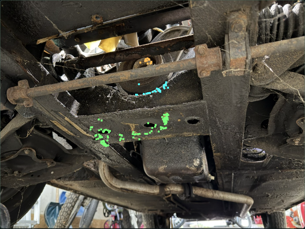
The main reconstructed patch angles are about 85.5° to the hub patch and 70.8° to the rim patch. A separate camera solve gives about 89.4° to its seven-point rim patch. The prior native forward-web plane was only 17.1° from a plane perpendicular to the modeled crank axis. That contrast supports a lower-face interpretation. Curved hub/rim surfaces, sparse sampling and camera variation prevent assigning a precise factory face angle, body axis or engine pose.
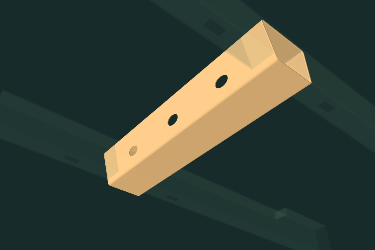
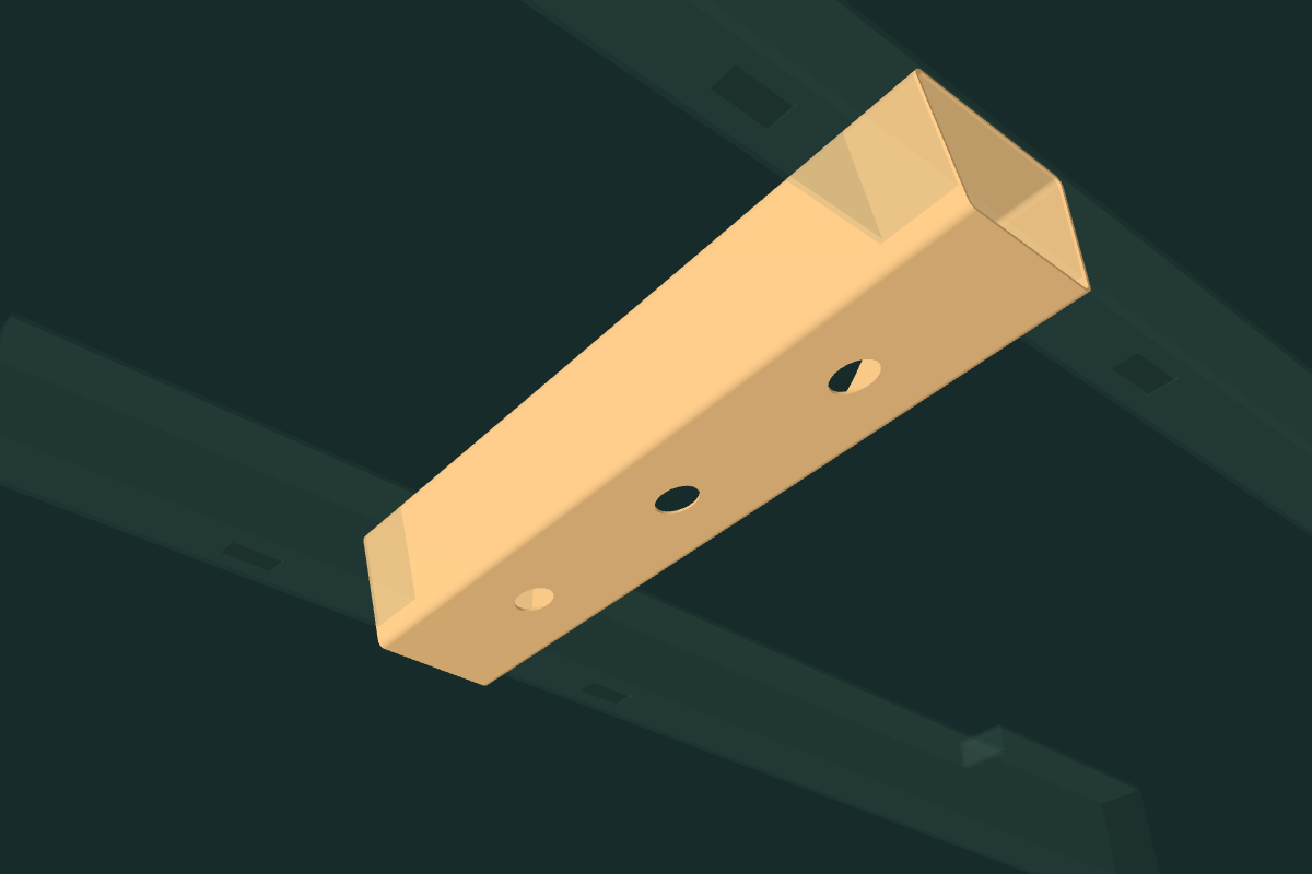
The new horizontal lower plane is a construction choice within the retained shell, not a measured factory plane. The X stations, ellipse radii, gauge and selected Z row station remain unmeasured. Complete outer bounds and the saddle stay; the other fourteen native groups, rail/pickup dimensions and engine/body poses stay. This corrects a face interpretation, not the unresolved chassis width, low exhaust or fitted common frame.
Native checks confirm three open lower passages, adjacent material, closed former forward-web passages and no material changes outside those aperture regions. Ten positive scoped crossmember/rail or suspension source contacts remain, including the existing wishbone and spring-seat overlaps. These are drawing relationships, not actual-car interference, loaded support, repair dimensions or verified replacement clearance. No neighbor is moved or cut to hide them.

Folded lower-link body brackets
The previous pickup references were four separate flat plates per side. The replacement photographs for CZJ542 and CZJ543 show a folded connecting web, ramped sides and unequal opposed openings. Each side now has two connected channel comparisons around its retained lower-link axes.
British Motor Heritage assigns CZJ542 to right-front/left-rear positions and CZJ543 to left-front/right-rear. These catalog roles are recorded separately from the generic CAD sections: the exact handed pressing and installed access-face direction remain unverified. The model keeps the existing illustrative pin-head direction.
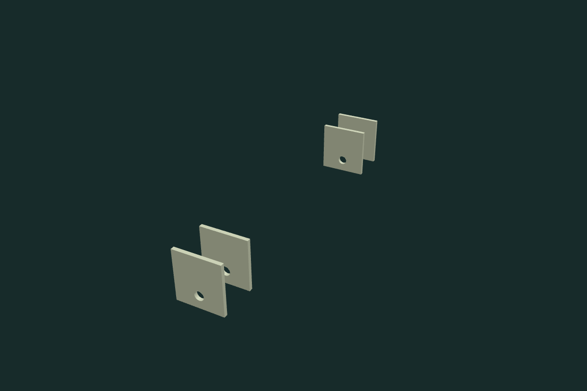
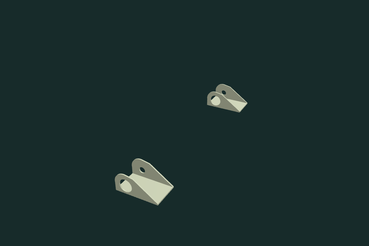
The 2.54 mm gauge, 13 mm access radius, ramp and web are selected construction dimensions. The 6.25 mm pin-opening radius and pivot coordinates are retained estimates. Photographed extra holes and square openings are not copied as a drilling or weld map. These matched isolated images hide the rail, arm, bushes and hardware.
Static source overlaps remain per side: rail 1,725.53 mm³, arm 1,247.70 mm³ and bush flanges 3.00 mm³. Pins and retaining hardware do not overlap the new bracket source. The small rubber contact is not a compressed-bush model. No neighboring component is moved; these relationships do not establish actual welds, loaded alignment, strength, tool access or a replacement path. Existing upper/lower spring registration gaps remain.
Independent native export
Checks cover valid positive solids, STEP round-trip, local openings/bores, source scale and retained drawing datums. They do not certify fitted geometry or any structural/service result.
Give the spring and damper a formed tower
The supplier’s three CZJ676 H-frame views show boxed and curved towers beneath flat, flanged damper platforms. The manufacturer distinguishes the rubber-bumper H-frame and wheelhouse applications from earlier configurations. These comparisons replace the model’s freely standing open cone and thick upper-seat slab with a boxed inboard wall, curved outer hood, open lower mouth, thin upper annulus/return and raised platform flanges.
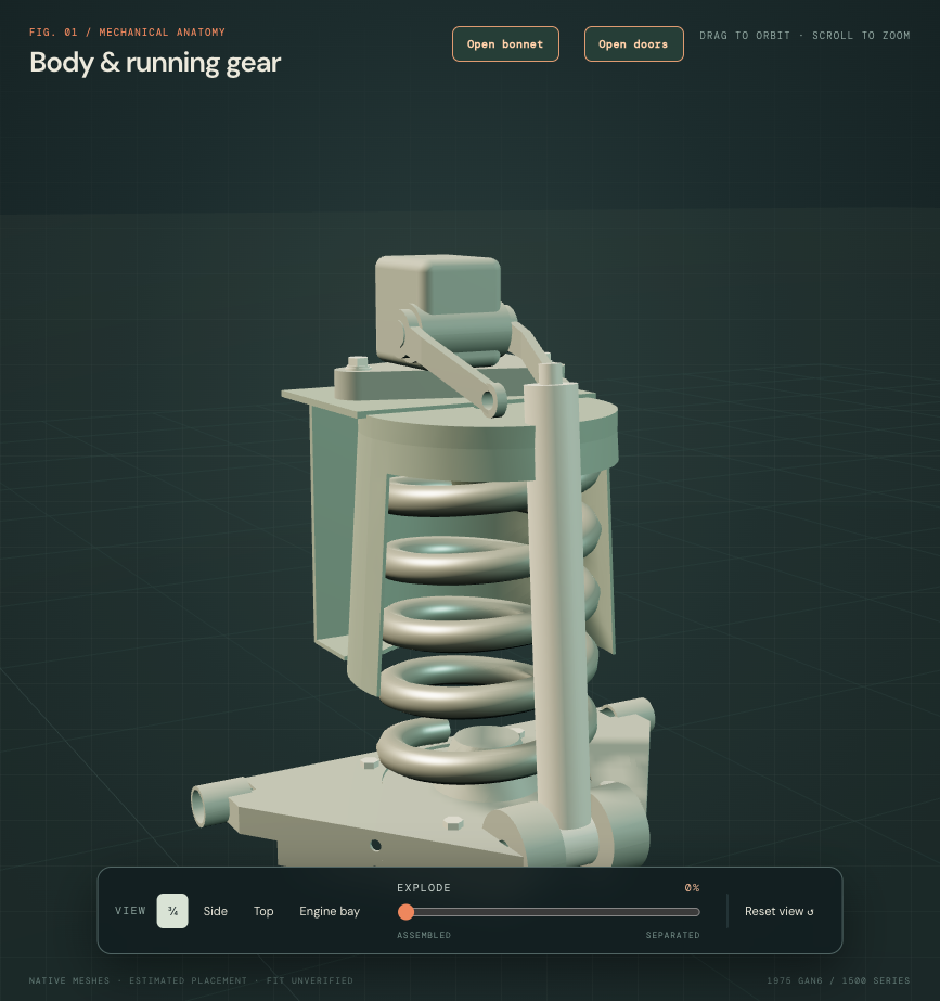
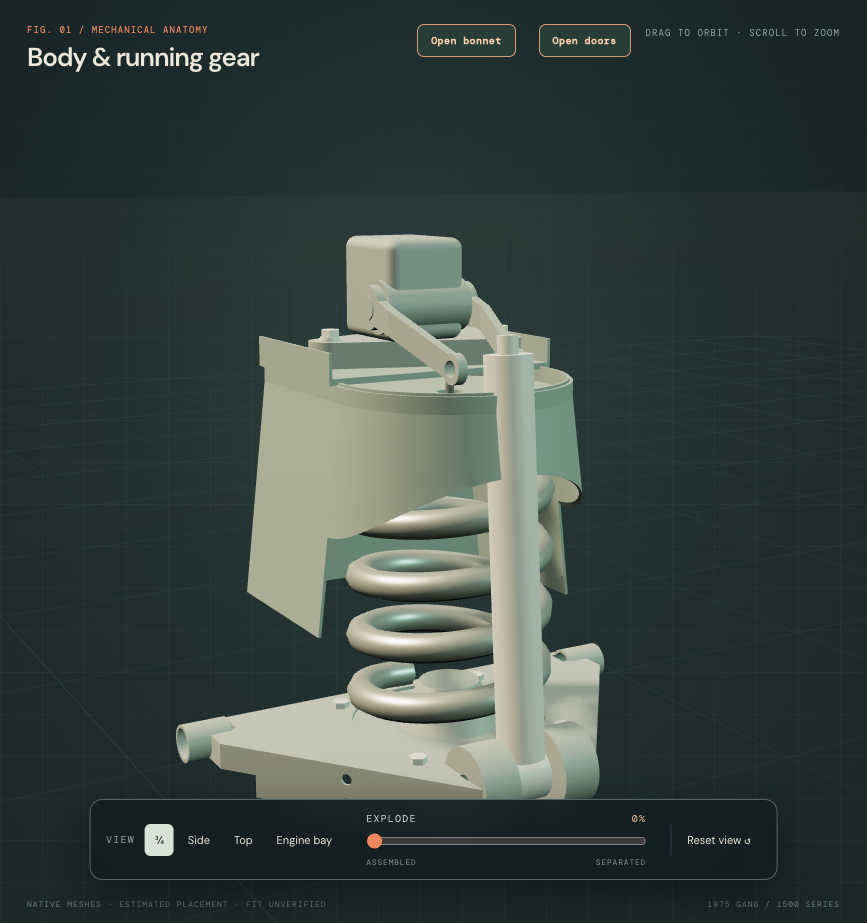
The rail, spring, lower pickup, upper-seat bearing level and damper mount stations stay fixed. The hood reaches the retained platform underside; its upper outer curve follows the estimated seat return. The D section, wall gauge, lower arch, cap, height transition and flange sections are estimates. The outboard arch is a chosen opening, not a traced factory aperture or a verified working clearance. Wheelhouse geometry stays unchanged; its seams and tower laps remain unregistered.
The previous lower drawing gap remains, and the upper coil/seat overlap is unresolved. No source component was moved to hide either. The existing owner photographs establish assembled context without exposing the hidden upper seat. The available workshop segments do not include the applicable front-spring removal page. This structure does not establish a safe support state, spring-release sequence, welding plan, load capacity or verified removal path. Welded body groups stay fixed during inspection.
Earlier continuous-rail reconstruction
The overlapping hollow rail/stub boxes are replaced by one connected hollow shell per side. Their outer bounds and forward pickup-region material stay unchanged; the joined internal cavity replaces doubled walls. The old stepped longitudinal envelope remains an estimate. The assembly photographs do not calibrate the actual rail curve or establish this car’s chassis alignment.
Owner IMG_6914 and IMG_6919 show a formed broad face with three apertures. The earlier construction interpreted this as the forward web; that interpretation is superseded by the current lower-face comparison. The rounded section, saddle opening, continuous rails and all suspension, steering and engine stations stay. The images below retain the historical earlier face choice.
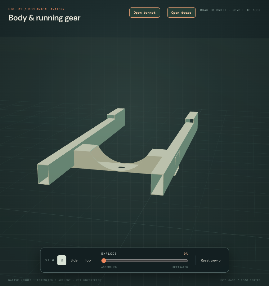
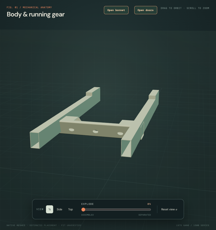
The owner’s underside photograph supplies visible face/opening context. Steve Clark and Bill Mohan’s firsthand 2006 BMH assembly photographs show formed-member and body-join architecture, including the rubber-bumper member. They are reference photographs, not dimensioned factory drawings or identification of this car’s fitted panels.
Front-web slope, corner radii, saddle forward limit, hole row/axes/radii and projected 2.54 mm wall are construction estimates. The earlier forward-web interpretation is superseded above; the exact lower-face tilt and hole map remain unmeasured. Longitudinal curvature, hidden reinforcements, seams/laps, actual section and repair/corrosion history remain unresolved. These references are not a drilling, welding, alignment or jacking template.
Native checks confirm continuous rail cavities, retained forward rail material and twelve unchanged surrounding source meshes. The three front apertures have real void and adjacent-material checks. Selected current exported sump/pulley shapes have zero crossmember source intersection at the held drawing pose; this is not a full-car or fitted-clearance audit. Rail/crossmember source overlaps remain unregistered sheet joints, not verified weld geometry or strength.
The frame references stay fixed during illustrative separation. Component support, fastener access, load restraint and actual extraction clearances require fitted geometry and applicable procedures before a replacement rehearsal can be trusted.
Underbody registration remains unproven
Original IMG_6915 andIMG_6919 were located and their capture metadata checked. A camera trial based on two outboard crossmember apertures could not reliably reproduce the middle aperture and pulley context. The apertures’ dimensions, spacing and planar face are themselves construction estimates; dark-region centroids are not surveyed mechanical axes. The capture’s24mm equivalent focal length is useful metadata, not a calibrated camera.
A proposed forward exhaust crossover was withdrawn. Visible pipe overlap in these oblique images does not establish a cross-car direction, longitudinal crossing plane, coupling or catalyst configuration. Passing CAD checks did not justify that route on the actual car. The engine, frame, sump, exhaust and all other modeled geometry remain unchanged by this review; the retained exhaust route is still an unverified reference.
This pass produced research evidence, not new geometry. The precise gap is a common registration using identifiable non-collinear features or an accessible owner dimensional record. Project-specific saved measurement records were also checked in the accessible browser sources without finding the numeric survey; that does not mean the measurements were never taken or saved elsewhere. No new captures were requested.
Capture provenance, rejected candidates and the precise evidence gap ↗
Transverse scale remains unresolved
A new partial-rim comparison gives an outer-aperture-span/pulley-diameter ratio of about 1.19–1.31 across the recorded photographic hypotheses, versus 2.517 in the current native frame/pulley. It strengthens the transverse construction concern without establishing a fitted width. A different engine offset alone cannot change that native size ratio. Inspect the original views, circle assumptions and conditional catalog comparison ↗
No aperture, rail, pickup, wishbone or engine coordinate is changed by this evidence pass. Resolve matching physical features and scale before revising their shared geometry.