Connect the
lower joints.
Paired inner bush comparisons and hollow arm eyes now lead to a forked outer joint, a separate bored kingpin foot, stepped lower pin, cotter and end closures. The wishbone plan, inner pivot centerlines and neighboring running-gear positions remain drawing references.
Inspect the interfaces
A meaningful size correction with a limited source
Factory PDF p. 141 lists four 2A4272 inner fulcrum pins, eight 8G621 lower-link bushes and four 2A4024 special washers/nuts. Two bushes now meet at each inner eye; the old model had one filled cylinder at each pivot. Those old bush and pin envelopes were about 79.59 mm and 30.48 mm in diameter respectively, derived from arbitrary body drawing units.
The supplier’s A486/8G621 stock description lists a 23–25 mm tapered outside diameter and 12.5 mm bore. These radial values guide a replacement comparison, not a measurement or identification of this car’s fitted bushes. The same listing gives 28 mm and 17 mm axial lengths without section datums sufficient for this assembly. Both readings are retained in metadata without being applied as a fitted stack. Its metal-insert construction is not reconstructed.
MGOC’s own suspension listing identifies the GHF223 retaining nut as 3/8 UNF; the pin’s terminal envelope uses the corresponding 9.525 mm nominal diameter without threads. The 12 mm shoulder, head, length, washer shape and nut profile remain estimates; the thread designation does not establish any of those dimensions.
Outer fulcrum and kingpin foot
The earlier shared-front factory drawing, p. 139 separates the lower link, 2A4020 fulcrum pin, kingpin foot, 51K1769 standard cotter, 51K3424 small-end blanking plug, 8G589 screwed large-end plug, UHN400 nipple and 2A4205/2A4206 rings. Its 51K2751 oversize cotter is a distinct alternative, not selected here. This earlier illustration supplies topology, not a 1975 fitted-parts identification. MGOC’s current Midget listing corroborates the lower-pin and different end-plug roles.
Two bored arm ends replace each filled outer cylinder. An estimated central fork opening receives the bored kingpin foot; the separate stepped pin crosses both. The cotter has its own transverse hole beside a simplified pin flat. Different small- and large-end closures and two ring envelopes make the lower-joint relationships inspectable. The kingpin shaft keeps the prior inclination, upper station and 18.63 mm radius. It is removed from the legacy swivel-axle group, leaving spindle, wheel, brake and steering datums unchanged.
| Estimated construction only | Model value / limit |
|---|---|
| Fork gap / foot axial length | 40 / 30 mm. Not a measured fit or axial clearance. |
| Foot outside / bore diameters | 40 / 16.5 mm. No fitted bearing specification. |
| Pin central / end diameters | 16 / 18 and 20 mm. Smooth stepped envelopes; no thread pitch, hand, engagement or wear correction. |
| Cotter / hole diameters | 5 / 5.4 mm. Simplified straight section and pin flat; actual taper, clocking, seat and retaining thread unverified. |
| Plugs, nipple and rings | Estimated profiles and orientation. No lubrication drilling, sealed contact or actual plug direction established. |
Both axes remain at X magnitude .58, Y=.27, Z=1.20 in body drawing units, along Z. No new owner dimensions are applied. The separate kingpin/carrier study now replaces the solid carrier and upper joint with bored sections, independent bushes, dust tubes, thrust and an offset trunnion. Real reamed fits, shaft sections, shim stack and end float remain unverified. An estimated reduced upper terminal is added above the retained shaft-top datum. The anti-roll study corrects the former horizontal fixing pattern to the forward wall using IMG_6914 and the factory flat-plate arrangement. The old unsupported fixing in this fork gap is superseded. Six new reference bores and an estimated 40 mm-deep forward wall establish the constructed relationship; fitted coordinates, depth and drilling pattern remain unverified.
Declared local construction
Each tapered body is drawn 19 mm long with a 3 mm external lip and an estimated 29 mm lip diameter. These axial/lip dimensions are construction choices. Hollow arm eyes follow the comparison taper with a small display allowance, without modeling pressed rubber, bonded inserts or measured compression. The pan keeps its old plan and top station, with an estimated 2.54 mm plate/lip instead of a filled slab. Its former solid outer sleeve is now separated as described below.
The matching body reference now uses 16.5 mm-radius eye pockets, 6.25 mm-radius ear bores and ear offsets of ±.030 body units, replacing the previous bush-sized primitive pockets and ±.059 offsets. Pivot centers remain X magnitude .36, Y=.27, Z=.98/1.42. This changes a declared local construction around the new bush comparison; it does not identify actual body cutouts, pressed fits, pin engagement or loaded axial contacts. Eleven other front-structure mesh records are retained exactly.
Owner underside photos retain their role as arrangement evidence without a calibrated inner-pivot survey. Fitted bush material, sleeve structure, worn eye condition, pin shoulder, body bracket span, washer orientation, thread engagement and loaded rubber compression remain unverified. A clean model bore is not a replacement-part compatibility test or a drilling template.
Workshop and travel boundaries
Arm, inner bushes, kingpin, pins, cotter and end closures have separate inspection translations. The kingpin and carrier share a display offset only; that does not prove retained ownership during service. These do not release spring load, prove pin extraction or articulate a suspension joint. No safe support state, sequence, torque, alignment, available tool room or verified removal path is supplied. Retain the spring, frame, anti-roll bracket and surrounding components when identifying the chain; their common registration is still estimated.
Actual outer thread engagement, cotter taper/clocking and the upper trunnion remain unresolved. MGOC describes 2A4082 as the front shock-absorber lever-arm buffer, which narrows its assembly role but does not locate this car’s attachment or loaded contact. No new rebound stop or suspension travel limit is inferred. The existing AHA6378-style inner spring stop remains a separate comparison.
Connect the lower spring seats
The former pair of solid cylinders at each spring base is replaced by a separate hollow formed seat and four fixing sets through shared wishbone bores. The factory plate, PDF p. 141 / printed 107-E26 lists two 21A137 seats, eight 53K1368 bolts, eight LWN405 shakeproof washers and alternate nuts. The supplier photo and listing support the four-ear, raised-center arrangement and nominal 5/16 UNF × 3/4-inch screw comparison. They do not identify fitted parts.
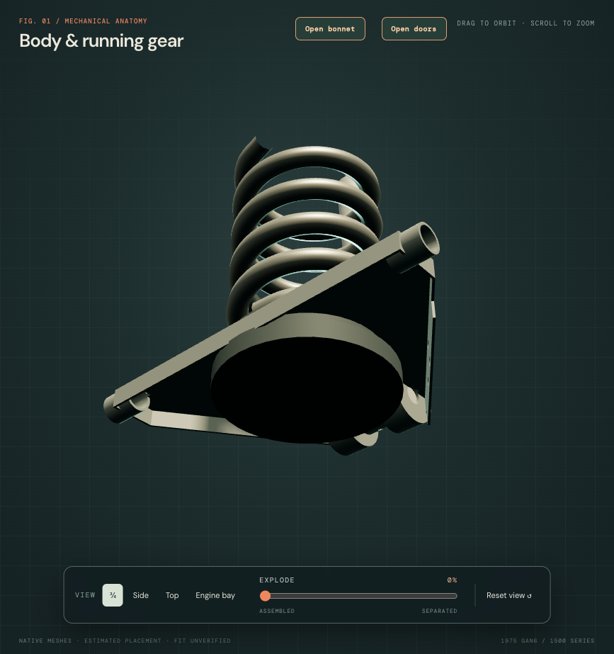
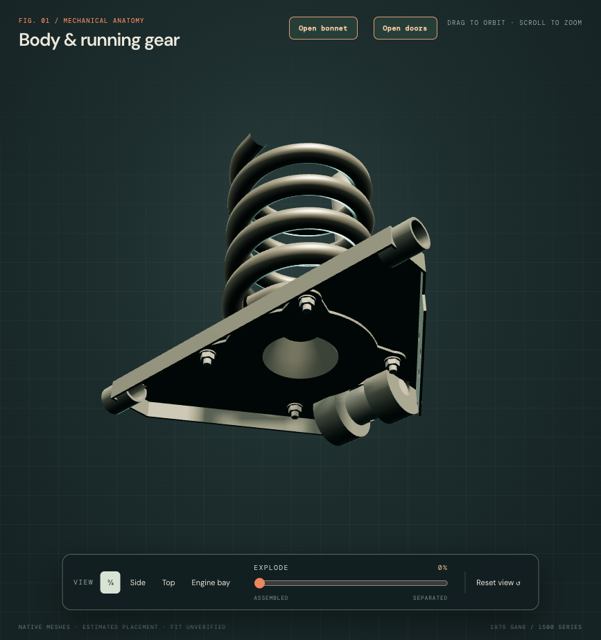
The seat profile, 3 mm sections, 95 mm mounting radius, hole clocking and clearances are construction estimates. Smooth washer rings represent the unloaded factory shakeproof role. Thread forms, teeth and engagement are not reconstructed. At this earlier seat revision the legacy spring helix and suspension datums retained their physical positions; the separate coil revision below supersedes that helix. The existing spring labels remain correct because the viewer reflects the legacy drawing roots into the canonical +X vehicle-left frame.
At this historical seat stage the retained legacy coil’s lower wire was about 7.6 mm above the estimated flat seat face. The coil revision below supersedes that separation; no wishbone was moved to hide it. The parts illustration supplies no safe spring-release procedure, torque, restraint, tool access or verified removal path. Separating these display groups is illustrative only.
Separate effective coils from total turns
The factory general specification, PDF p. 13 / printed 04-3, lists seven effective coils. The former viewer helix had five open turns and about 23.7 mm wire. The new native comparison uses seven central turns plus two estimated end turns, reduced end pitch and ground-plane cuts. Lee Spring’s generic end-count guidance distinguishes effective coils from total turns; it does not verify this car’s spring count or stiffness.
MGOC’s table lists 12.7 mm wire and a 4.12-inch coil diameter for both CHA129 and CHA570. The model conditionally interprets that diameter as 104.648 mm outside diameter, consistent with the supplier photos and its separate 105 mm outside-diameter discussion for lowered Midget springs. The table header itself does not specify mean versus outside. CHA129 through GAN6-171477 and CHA570 from 171478 remain distinct, unselected comparisons.
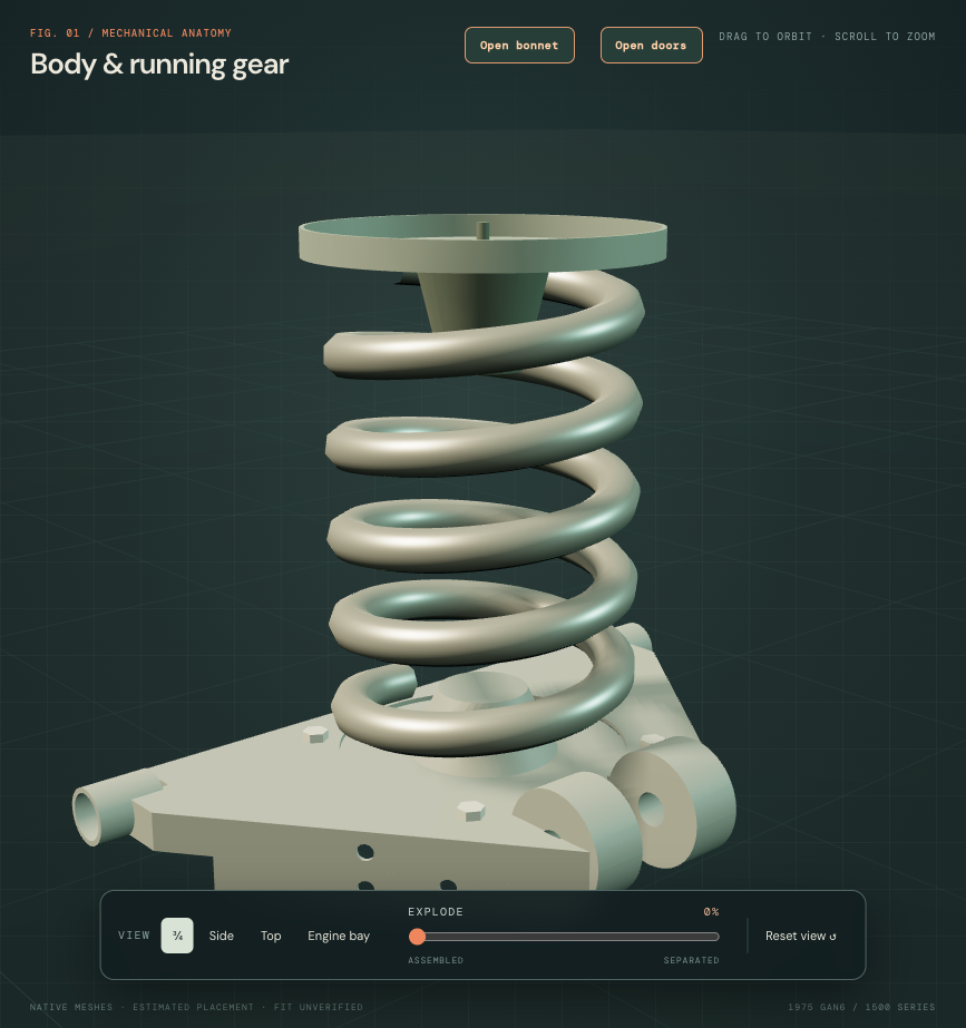
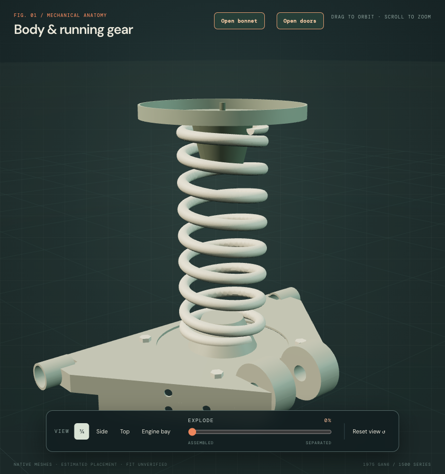
Spring axes and neighboring assemblies stay. The earlier centerline endpoints become the new ground-plane bounds: a 245.533 mm display height. End pitch, grinding, phase/hand and two end-turn construction remain estimates. This does not impose factory free length or test-load length on the actual car. The manual’s inch/metric pairs are retained as printed; no spring rate or preload is calculated.
The lower and upper seats are separate estimates. The new ground planes do not establish loaded contact, available travel or withdrawal clearance. The lower ground plane differs from the estimated flat seat station by 19.473 mm, and the upper by 9.313 mm. The nearest lower-seat surface is its raised dome, about 6.167 mm away. These are model registration differences, not measured vehicle clearances. Earlier 7.6 mm legacy-wire separation is historical and superseded by this revision. Neither the factory test load nor this display pose identifies the actual spring or suspension state. No safe spring-release procedure or verified removal path is supplied.
Open inner recess and a connected pressing
The earlier arm filled the space between its inner eyes with a straight strip and exported six overlapping solids. MGOC’s AHA7029 replacement photographs show an open inner recess and a downward formed return. Both arms now have that architecture as one connected reference solid.
The old 80.433 mm-radius spring opening left only 12.7 mm of sheet at the inner edge. This revision selects a 60 mm-radius opening and an estimated curved recess, retaining the spring axis, four seat fixing axes, inner eyes, outer fork and anti-roll wall. The separate coil comparison has a 104.648 mm outside diameter. That comparison is not a measured operating clearance. The recess is shallow within the retained pivot/spring frame; it does not recover the full factory contour. Its downward return stays outside the unchanged seat disk in this construction. The new recess profile, opening size and 2.54 mm projected sheet gauge remain construction estimates; no dimensions are inferred from the supplier pixels.
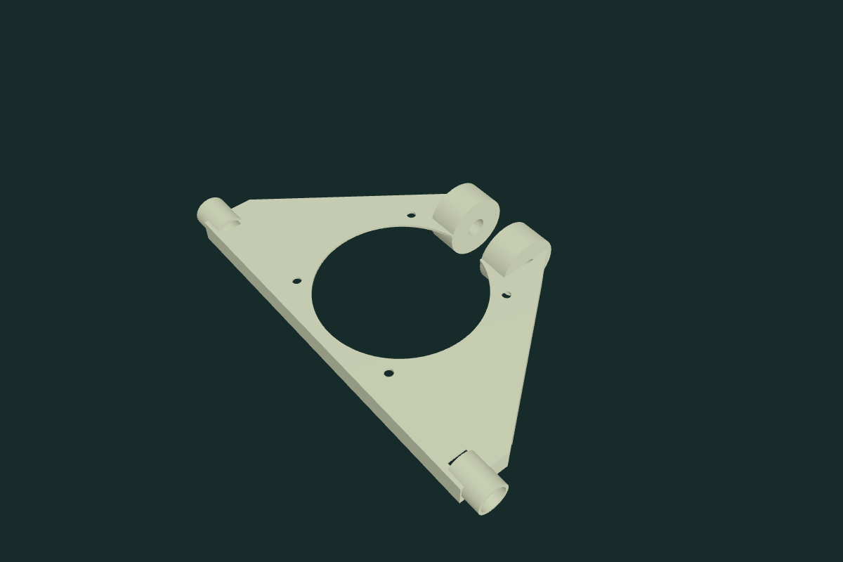
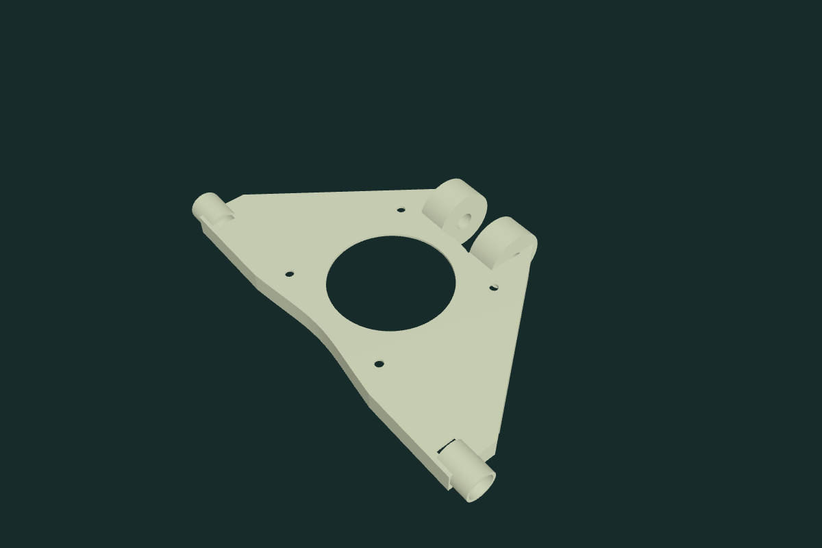
These matched isolated views hide the spring, joints and body. The STEP round-trip checks cover connected solids, retained eye/fork/wall material, all eight fixing passages, open cavities and source seat contact. They do not establish actual sheet development, welds, strength, spring restraint, travel or a replacement procedure.
Native export
Build this final stage after the original fulcrum and swivel-profile stages. The front structure continues to use the unchanged declared pickup construction in the original export. Checks cover valid solids, open local passages, scale and retained reference stations. They do not certify fitted operation, strength or service access.
Inspect the revised raised-journal pin and tapered upright references ↗. The original journal dimensions and height remain unverified estimates.