Behind the fascia.
Around the column.
The old solid dashboard block and four discs are replaced by an open-backed fascia comparison. Separate circular mounting envelopes, glovebox liner/lid, a folded radio/speaker console, documented mounting gaps and column references expose the surrounding relationships.
Inspect the structure
The fascia has a lower steering-column relief and open circular and glovebox apertures. Its top rail is a padded-shape envelope; wall gauge, padding and contours are estimates. Five blank circular mounting envelopes reproduce the factory drawing’s general layout without assigning fitted speedometer, tachometer, gauge or socket identities. No readings, wiring or capillary connections are simulated.
Coordinated cabin-height reference
The old fascia rail rose about 169.3 mm above the modeled scuttle plane and occupied the lower glazed field. The new shallower face has an estimated center top at the scuttle reference height, with less transverse crown and a thinner padded-rail envelope. This follows the supplied cabin context and factory NA panel layout qualitatively; neither supplies a calibrated height, section or fitted instrument map.
The five circular references retain their radii and X spacing, while their heights follow the shallower face. Glovebox/liner references retain their earlier estimated positions. The former squat radio box and unsupported upper switch block are superseded by the console correction below. Dark fascia/liner/lid/console materials follow the visible dark trim context; blank circular faces still have no assigned working instrument identity.
The wheel’s X/Z position and the lower pinion point stay. Its height derives from the revised fascia relief at the retained face plane, about 87.5 mm below the previous drawing. Shaft/sleeve, pinion input direction/coupling, wheel plane, upper support, body flange/seal and bulkhead opening follow that shared construction. Rack, track, mount and seat datums stay. Every new position, section and derived shift is an estimate, not an owner measurement or a fitted steering adjustment.
Earlier column checks found no column/face/instrument intersections and an open body passage. The revised console now has a recorded source intersection with the tunnel, detailed below. Six previously recorded column-to-pedal-housing/cover/seal source contacts remain unresolved. These are reconstruction conflicts, not proof of actual-car interference. No steering ergonomics, loaded support, collapse action or operating clearance is verified.
The former elevated nozzle pose is superseded by the estimated shared nozzle, rear dash-top and padding construction. Its slots and fixing roles explain an attachment relationship; fitted positions, upper hose clearance, remote supply, hidden joints and loaded seals remain unresolved.
Fascia and instrument separation remains illustrative. No verified wiring release, instrument withdrawal, body bracing, column support/release, dash replacement sequence or removal path is established.
Keep the market and chassis evidence
Factory PDF p. 278 distinguishes the North America/Sweden AHA8866 fascia, AHA8606 support, switch nacelle and separate radio-panel variants. PDF p. 279 separates the CHA55 cubby lid, hinge, stay, lock and fittings. The new liner, lid and hinge/lock cues use that architecture only; their shapes and positions are unmeasured. A plain center panel does not identify this car’s fitted radio or switches.
Owner IMG_6341 supplies LHD cabin and upholstery context. It does not calibrate hidden supports, the fascia profile, instrument apertures or glovebox hardware. Seats keep their earlier stations. The coordinated cabin-height construction below now revises the fascia and wheel/column references without claiming fitted registration.
The column shares a revised estimated axis
IMG_6341 supports more wheel setback into the cabin than the former near-fascia center. The reference wheel center moves 245.5333 mm rearward as an uncalibrated construction estimate. Its complete rim/hub/spoke plane, column shaft/sleeve, upper support and body flange/seal/aperture follow the same axis. The thick sleeve now ends at the reference body crossing, leaving the lower shaft exposed. The fascia/component heights and column axis now follow the coordinated cabin-height construction; seats keep their earlier stations. See the column relationship correction for evidence and limits; no fitted dimensions or removal paths are inferred.
Factory PDF p. 137 lists the GAN6 North American CHA341 collapsible-column comparison and a four-fixing body relationship. PDF p. 138 distinguishes flange/body sealing and other column/lock configurations. The new upper support, body flange and seal are estimated constructions; the four-hole pattern is not a factory drilling template or fitted fastener map.
An estimated elliptical bulkhead opening follows the revised estimated column axis at the retained body-plane crossing. This removes the former solid-panel intersection in the reference. It does not verify the actual opening, seal seating, column collapse, support load, bracket ownership or steering clearance. The existing pedal and separate slender-line openings remain independent.
Fascia, circular envelopes and lid separate linearly to expose reference shapes. They do not establish instrument withdrawal, lid hinge travel, column release or safe dashboard removal. Instrument identities, rear connections, support/contact, switch layout, harness interference, glovebox contents, lock action and fitted replacement paths remain unresolved. The visible faces and body coordinates are estimated geometry, not a faithful fitted fastening map.
Separate native reference
Construction checks cover valid solids, STEP round-trip, open fascia apertures and the estimated column/body opening. They do not establish operating instruments or fitted clearance. The column/wheel axis and associated body aperture change together; unrelated source geometry is retained.
Upper-dash outlet construction
The formerly elevated independent demister pose is superseded by two hollow nozzle comparisons beneath the fascia padding and a new rear dash-top pressing. The padding and pressing share two slots and four fixing passages; paired smooth fixings and upper hose cuffs expose the relationship. All shapes, positions, gauges, hardware dimensions and hose routes remain estimates. Inspect the construction, factory branch distinctions and unresolved supply/access. No fitted clearance or verified replacement procedure is established.
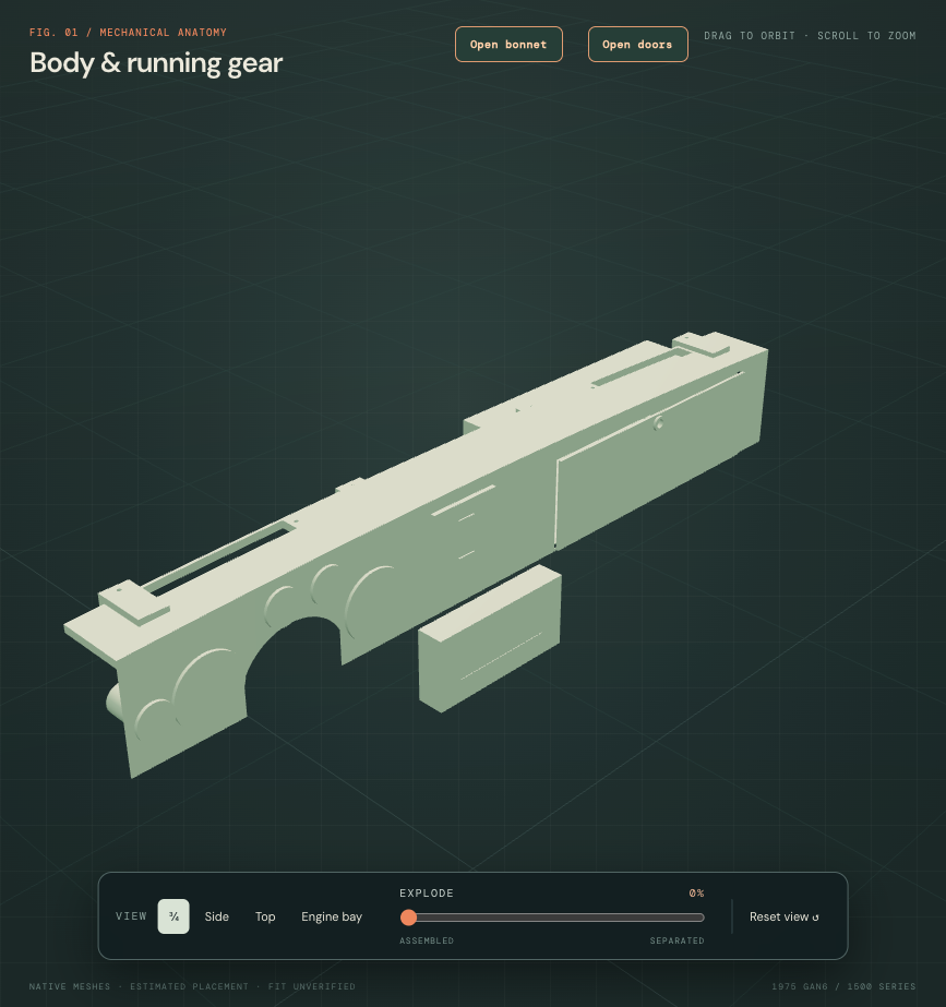
A rounded, open-backed fascia envelope
The thin flat face and rectangular top strip are replaced by one connected reference with a rounded upper brow, a thin top cap and an open underside. Five circular apertures, the glovebox opening, demister slots and their fixing axes retain their stations. The later console correction below withdraws the unsupported central cutout.
Before · flat face and square rail
After · rounded padded reference
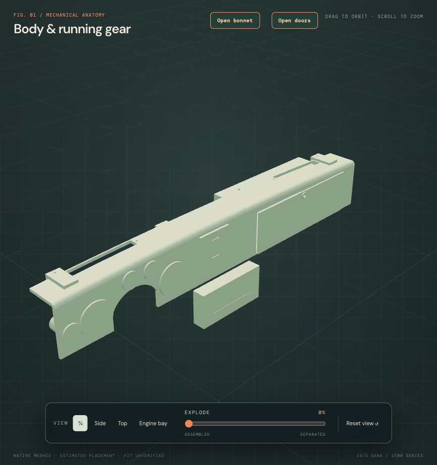
These matched diagnostic views hide the surrounding car and use the same neutral inspection material to expose the shapes. Production colors stay unchanged. These images document the brow revision; the later console correction below governs the current configuration. The circular faces remain blank envelopes; their instrument or control functions are unassigned.
What supports the change
Factory plate 278 shows the North American/Sweden AHA8866 fascia architecture; plate 279 separates the CHA55 cubby lid and its hardware. The Moss 453-817 replacement photograph supports the broad padded face and rounded brow. This modern cover is a comparison, not fitted-part identification. Owner IMG_6341 supplies partial cabin context and does not expose the hidden construction.
The 8 mm face/cap section, 12 mm outer nose radius and 24 mm front-apron drop are selected estimates. The envelope does not reconstruct a steel/foam/vinyl laminate, adhesive, measured padding thickness or impact behavior. Width, top curve, presentation plane and surrounding assembly poses stay. Ribbing, textures and added instrument labels are deferred.
The former generic support cues overlapped the brow reference by about 69,033 mm³; those four unsupported blocks are now withdrawn. Glovebox hinge/lock cues still overlap the fascia by about 2,210 mm³. Existing bezel contacts remain. These are source-model discrepancies, not fitted interference findings or proof of loaded retention. Factory plate 278 lists four shroud-nut roles and one LH support plate; the withdrawn four generic support cues were not four identified AHA8606 plates.
Inspect the fascia in the car ↗ · Read geometry and contact checks ↗
Workshop boundary
Moss describes replacing the original foam and vinyl; that does not supply a complete factory fascia-removal procedure. No additional applicable operation text was accessed here. The model’s composite-envelope separation is illustrative. Hidden core attachments, gauge retention, wiring, column support and a verified actual-car extraction path remain unresolved.
Current source: fourteen groups and thirty positive valid STEP solids. The latest console revision retains eleven prior mesh records/native group volumes, six neighboring sources and all 160 assembly anchor fields. These checks establish reference geometry, not fitted accuracy.
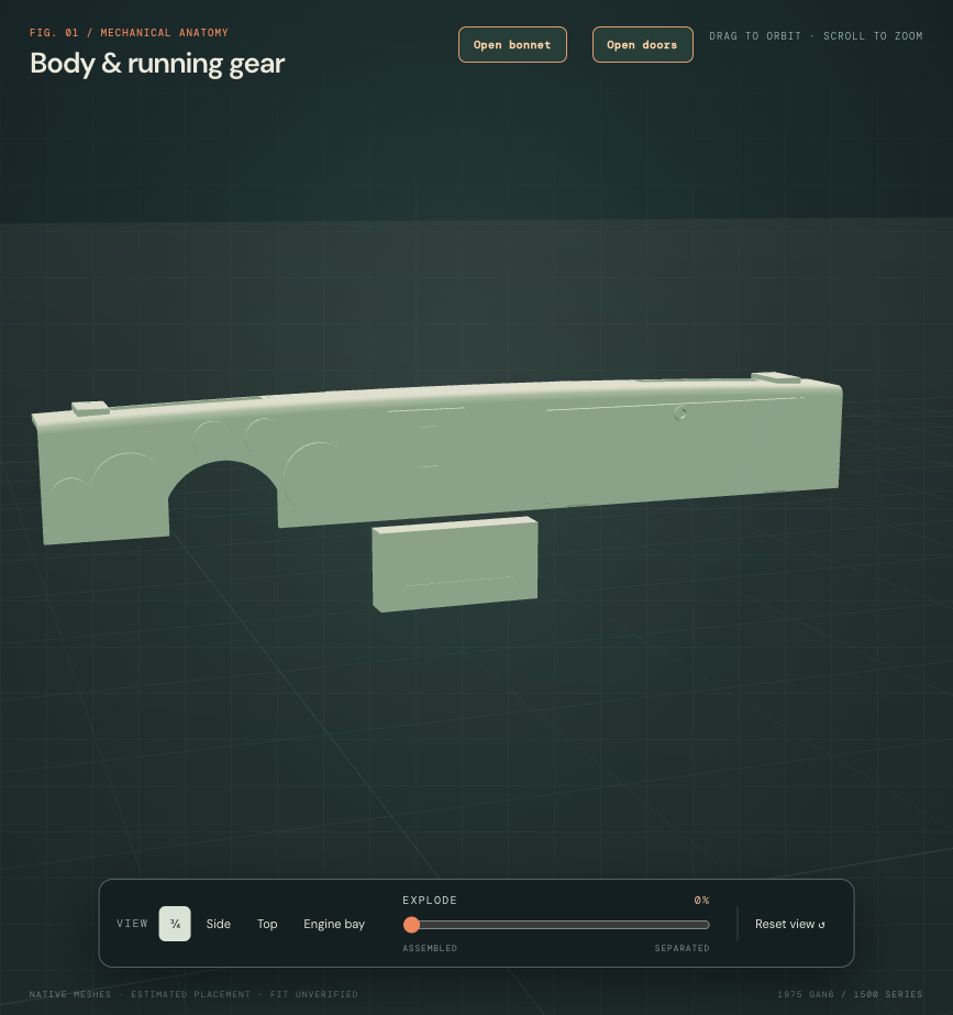
The console belongs below the fascia
The large upper “switch nacelle” block and its unsupported fascia cutout are withdrawn. A folded, open-backed console now has an upper speaker-grille opening and a lower radio opening, matching the assembled layout in the MGOC R350 fitting sheet. A separate coarse open grille replaces the former block. The old radio recess was blind; both console apertures are now open through the native sheet.
Before · unsupported upper block
After · two-level console reference
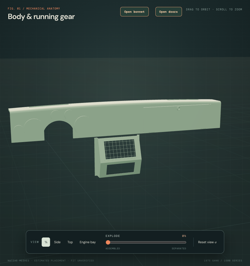
Matched diagnostic views use the same neutral material. Surrounding body parts are hidden here; the tunnel comparison below exposes the remaining relationship.
Roles are distinct
Factory NA plate 278 lists CHA59 console and BHA4823 grille roles. AHA8570 remains an unplaced switch-nacelle role; it is not renamed as a speaker grille. The MGOC console photograph supports the angled faces, side walls and mounting returns. These are catalog comparisons. Owner IMG_6341 does not identify the fitted console, radio or hidden attachment map.
The front-face width, top station and radio-opening X/width/height retain inherited drawing values. The former radio height is superseded by the documented upper-speaker/lower-radio order. Console height, face angles, axial stations, 1.5 mm projected sheet section, returns and coarse grille geometry are estimates. There is no modeled radio, speaker or wiring, and no new body hole or fastener map.
The source console overlaps the retained tunnel by 522.84021 mm³. Its top is 8.4667 mm below the fascia drawing datum; this is not a spacer specification or fitted clearance. Body, tunnel, column, lever and support references stay fixed. No source is moved or body cut invented to erase the discrepancy.
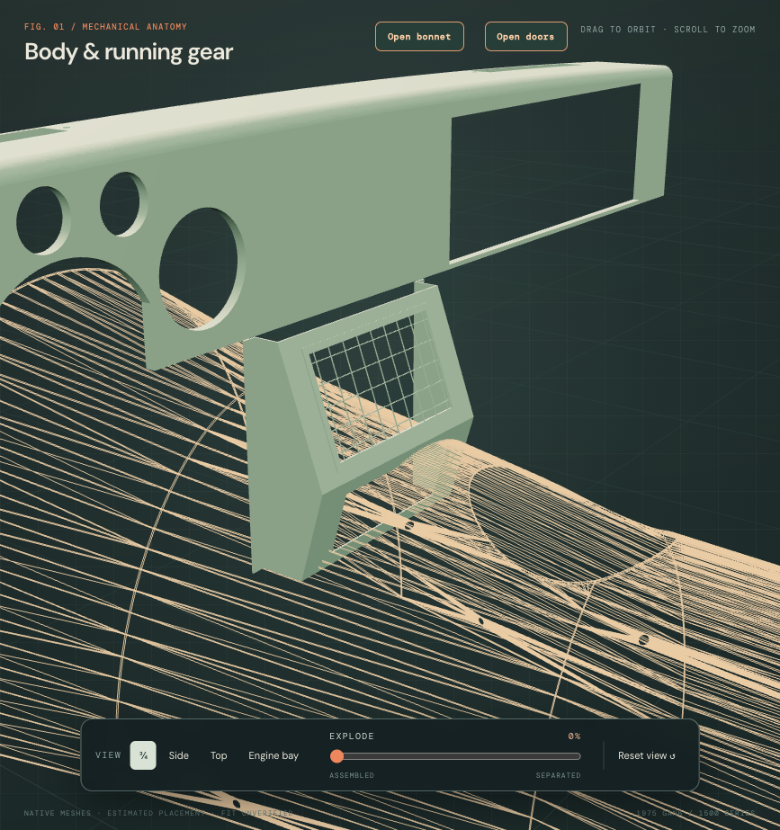
The tunnel is wireframe in this diagnostic view. This is an obstacle comparison, not a removal path.
The fascia mounting chain remains unmodeled
Factory plate 278 distinguishes four shroud-fixing nut/washer roles from one LH AHA8606 support plate. A bounded primary-source search and the existing cabin photograph did not recover a supported receiver/axis chain. The four invented rectangular support blocks are withdrawn. No replacement body holes, studs or support locations are fabricated. This is a documented gap, not proof that the fascia is physically self-supporting.
Documented fitting roles, unverified actual-car procedure
The supplier fitting sheet describes attachment beneath the dash and to the engine/gearbox tunnel. Its fastener suggestions are qualified; they are not assigned to this car. This aftermarket guide is separate from a factory 1975 removal procedure. Hidden receivers, access, wiring and a verified extraction path remain unknown.
Inspect the folded console ↗ · Inspect the upper grille ↗ · Read native checks ↗