Connect the wheel end.
Separate the seals and retention.
An integral-role journal/flange and connected dished backplate now surround the stepped hub, bearing/retainer and half-shaft references. Separate sealing and retaining hardware exposes the hub-to-shaft-to-drum-to-wheel stack. The mirrored right-side source has the same construction roles, with no fitted thread assignment.
Left rear interfaces
Factory roles and manufacturer comparison
Factory PDF p. 146 distinguishes rear bearing nuts with right/left-hand threads, locking washer and axle variants. P. 147 separates BTA806 disc-wheel shaft, 2A7087 hub, GHB130 bearing, GHS147 lip seal, ATA7225 ring and 2A7091 gasket. Wire-wheel and later axle/differential branches stay distinct.
P. 148 supplies handed 1500 backplate roles, eight backplate screws/locknuts and four drum screws for the car. The supplier axle listing independently identifies the shaft-retaining screw role. These establish relationships and quantities, not this car’s fitted part identity or hole map.
NSK 6207 boundary dimensions provide the retained 35 × 72 × 17 mm comparison only. They are not an approved GHB130/fitted cross-reference or a loaded bearing specification. Existing owner evidence provides wheel/underbody context, not a calibrated wheel-end survey. No new direct owner measurements are applied.
Reference corrections are not repair dimensions
| Construction | Change and limit |
|---|---|
| Axle tube / journal flange | The prior tube ends at −55 mm relative to each wheel datum intersected the flange/backplate references. Only those tube ends shorten 3 mm to the retained flange’s inboard plane at −58 mm. Seven other axle-source meshes remain identical. This is source-geometry reconciliation, not measured axle length, a repair cut or evidence of a fitted seam. |
| Journal / backplate | A 1 mm journal shoulder extension joins the old disconnected shapes. New 58 mm-radius mounting faces and a four-hole 96 mm PCD share 4.5 mm-radius bores and hardware envelopes. These sections and the entire map are estimated, not a factory drilling/welding template or verified support. |
| Hub / bearing | The connected hub bearing-pocket start moves from −36 to −33.5 mm to meet the declared boundary face: a +2.5 mm drawing change. Bearing center −25 mm and all loaded fit/clearance/face details remain unverified. Nut/flat tab washer are separate; actual thread hand, locking/bending and torque are not established. |
| Shaft / drum / wheel | Wheel mounting +20 mm, shaft flange outer face +15 mm, gasket 8.5…9 mm and hub outer face +8.5 mm remain source datums. The 101.6 mm PCD is the existing supplier comparison. Native shaft/drum retaining bores and an access aperture are estimated relationships, not verified tool or withdrawal paths. |
Keep the sealing roles distinct
The supplier’s banjo-axle repair publication distinguishes the hub lip seal, shaft O-ring, gasket and journal sealing surface. Its repair-sleeve procedure is not transferred to this car. No worn journal, leak cause, sleeve need or installation specification is diagnosed.
The new face groove follows an estimated uncompressed O-ring envelope. That ring overlaps the gasket by 342.1469 mm³ per side and the shaft flange by 479.4976 mm³ per side. These static source contacts do not model rubber compression, material behavior or a leak-free seal. Groove, gasket and lip dimensions and all loaded contacts remain unverified.
Half-shaft and retaining hardware
The differential-support comparison extends only the two shaft meshes inward50 mm, moving their tips from ±90 to ±40 mm to meet revised toothless gear boundaries. Thirty other hub meshes remain identical. This is an unmeasured construction correction, not actual shaft length, splines or verified engagement. Four studs pass through the source hub, gasket, shaft flange, drum web and wheel pattern. Wheel nuts, one shaft screw and two drum screws per side are independently selectable; head, thread, countersink, seat and locking details remain estimates.
The original drum retained a nominal177.8mm bore and its estimated outside/axial station. The current replacement-boundary drum comparison below supersedes that cylinder;the original source remains available as a historical comparison. Its central opening and retaining/access holes do not establish service clearances. The independent native rear-brake mechanism now replaces the shoes, cylinder, adjuster and spring cues. Two backplate meshes receive separate estimated cylinder, bleed and handbrake apertures; thirty other hub meshes remain identical. External handbrake stations are unchanged. Fitted settings, pressure seals, loaded behavior and internal handbrake expansion remain unresolved.
No fitted axle/hub/shaft/bearing identity, thread loosening direction, bearing setting/end float, torque, seal compression, lubrication, actual wheel offset, brake adjustment, safe release/support order, tool access or verified withdrawal path is established. Explode offsets are illustrative. The applicable complete workshop procedure has not been validated against this fitted installation.
Native exports
Thirty-two source meshes contain seventy-six valid STEP solids. Checks cover shared backplate/wheel bores, open shaft/journal/bearing passages, reference-bearing-seat nonintersection, mounting hardware/hub nonintersection and drum/screw construction. Viewer checks cover metric scale/picking, bores and fixing occupancy, declared movement/isolation, source counts, links/downloads and mobile layout. These do not certify fitted clearance, sealing or operation.
A deeper drum exposes the retained wheel-end conflicts.
The original model was a 37.5mm-deep straight cylinder with a 200mm outside diameter and 64mm center hole. Delphi’s own BF1 catalog reports 208mm outside diameter, 178mm bore, 74mm centering diameter and 61mm total / 47mm inner height. These independent replacement boundaries now inform the comparison. The general seven-inch reference remains 177.8mm; the new bore follows the published rounded178mm reading. Neither value identifies the fitted drum or establishes operating clearance.
Rimmer’s own2A7168P listing includes Midget1500 and shows a stepped machined face, tapered shoulder and flared open rim. Those features replace the flat cylinder here. The radial/axial section between the catalog boundaries is an estimate from that unscaled photograph. C&C’s DR178010001 listing associates2A7168/BF1 with the Midget family; its compact dimension notation lacks a legend and is not applied as a separate drawing.
Delphi reports92mm; the retained wheel/hub construction uses101.6mm. This comparison preserves the existing fixing, screw and access axes. It is neither an exact BF1 reconstruction nor proof of interchangeability. The outer wheel-mounting plane stays atX+20mm, so the deeper drum grows inward toX−41mm. The axle, wheel, hub, backplate, shoes and cylinder remain in their reference positions.
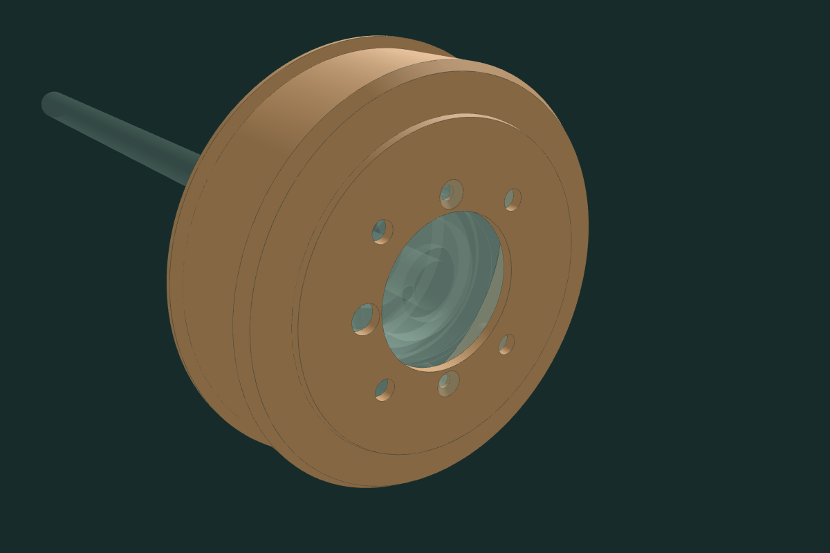
Seventy bounded static comparisons retain twelve positive pairs: the larger-depth comparison meets the old backplate, shoe webs/linings and small cylinder-boot regions. The native report records each volume. These are reconstruction discrepancies, not measurements of interference on the car. All30other hub-source mesh records and native volumes remain held; the full export still has32groups/76positive valid solids. Shared fixing/access passages remain open.
The inner-height reading is represented as the cylindrical internal boundary fromX−41to+6mm; the inner shoulder is estimated. No casting strength, heat capacity, wear limit, loaded seating, brake setting, actual-car release or drum-removal procedure is established. The0.2mm difference between rounded178mm and seven-inch177.8mm is not a brake adjustment or verified running gap.
The bolt-circle discrepancy stays explicit
A.B.S. 3430-S supplies an independent 101.6 mm bolt-circle comparison. Its own application table includes Midget 1.5, and its crossings include MG 2A7168 and Delphi BF1. The two manufacturers publish different boundaries:
| Published boundary · mm | Delphi BF1 | A.B.S. 3430-S |
|---|---|---|
| Outer / inner diameter | 208 / 178 | 210 / 178 |
| Total / inner height | 61 / 47 | 60 / 50 |
| Center / hub diameter | 74 | 74 |
| Bolt circle / hole count | 92 / 4 | 101.6 / 4 |
A catalog cross-reference does not explain the 92 mm value, make both products dimensionally identical or identify the fitted drum. No dimensions are averaged. The current Delphi-boundary drum comparison retains its 101.6 mm fixing map and remains a mixed reference, with the discrepancy disclosed. The drum, hub, wheel, backplate and their stations have not changed. The manufacturer's linked fitting PDF is a generic shoe/drum leaflet, not a dimensional section or a verified 1975 factory procedure.
Manufacturer crossings ↗ · Manufacturer applications ↗ · Reading record and limits ↗ · 32 mm shoe-width comparison ↗