Inside the
rear drums.
Separate steel shoes and linings, a hollow cylinder with slotted piston ends, retaining washer and clip, and a bracket, screw/wedge and tappets replace the former solid mechanism cues. Two spring references now end at explicit shoe-web eyes. These expose assembly relationships without simulating brake operation.
Left rear mechanism
Right rear mechanism
Factory roles and component comparisons
Factory parts PDF p. 148 distinguishes the GAN6-154101-on 37H8804/5 plates, GBS625 shoes and GWC1129 cylinder from earlier plate/shoe/GWC1102 branches. It lists separate 17H7613 Belleville washer and 17H7622 circlip, 17H7618 tappets and 17H7619 wedge, handed 17H7947/48 cylinder-end springs, 17H7621 lower springs and handed handbrake lever/boot roles. These are reference roles, not identification of the installed parts.
Mini Spares’ GWC1129 component photograph and specification support a twin-ended cylinder with slotted piston tips and an 11/16 inch (17.4625 mm) bore comparison. That supplier dimension does not become a measured bore or prove the fitted cylinder, nor does the Mini application define the Midget brake installation. The supplier’s 17H7618 tappet description and photograph support separate tappets meeting the screw/wedge in a bracket; all modeled sections and tapers remain estimates.
Mounting relationships now visible
Separate backplate interfaces
The factory drawing distinguishes the handbrake slot from the round cylinder mount. The former combined opening is replaced by a 20 × 25 mm slot at Y70/Z−23, a cylinder opening of radius7.5 mm at Y68/Z0 and a bleed opening of radius3.5 mm at Y76/Z12. All are wheel-relative construction coordinates, not factory drilling dimensions. Only the two backplate meshes change in the existing hub source; thirty other hub meshes remain identical.
Cylinder, shoes and retention
The barrel/pistons/boots shift 6 mm outward from the old cue to the retained shoe-web plane, while the inlet tip stays at u−35/Y68/Z0. The mounting neck passes through the plate with separate unloaded Belleville and open clip roles. Piston slots receive the thin web envelope; seal fit, stroke, pressure channels and loaded contacts are absent. No fitted hydraulic splice is verified.
Adjuster and return springs
The bracket is open across the tappet axis. A smooth square-drive screw and conical wedge remain separate from the two tappets. Upper/lower unloaded coil and hook envelopes terminate at explicit web holes. These show roles and source relationships; taper, travel, spring hooks/handing, preload and adjustment settings remain unverified.
External handbrake boundary retained
The external rod-eye stations stay. The earlier strap, generic pivot and solid boot are superseded by the two-lever comparison below; seventeen other handbrake mesh records remain unchanged. Fitted boot/backplate registration and loaded shoe-expansion behavior remain unresolved. The separate slot does not prove lever movement, leverage ratio, shoe contact or the remote body crossing.
A catalog width replaces the narrow shoe estimate
The earlier shoe rim and lining envelopes were 24 mm wide. A.B.S. 8606 lists a 32 mm shoe width and 178 mm drum association. Its own cross-reference includes MG GBS625, the role on the factory plate, and its application table includes the 1974–1979 Midget 1.5. That supports a replacement boundary comparison; it does not identify the shoes on this car.
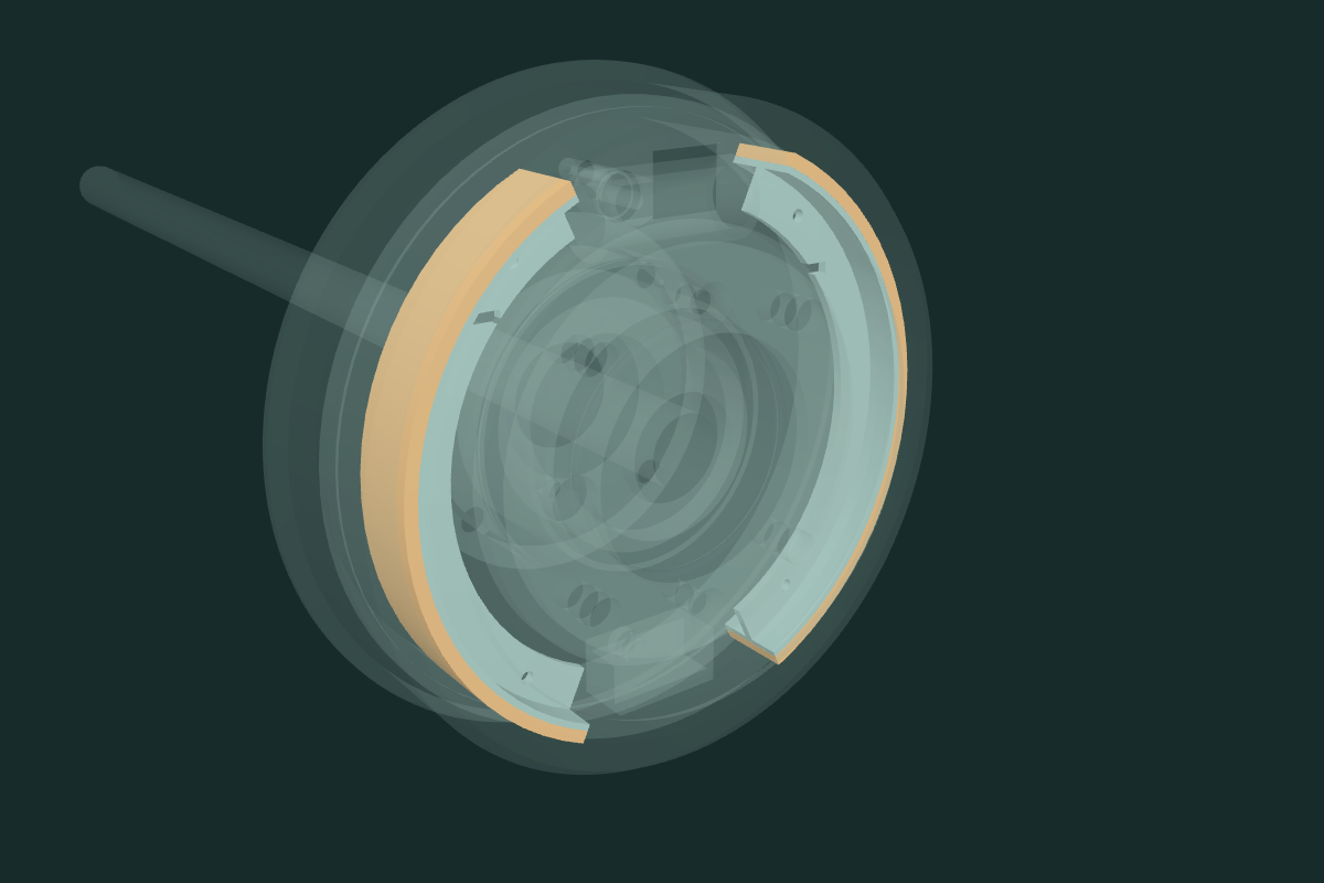
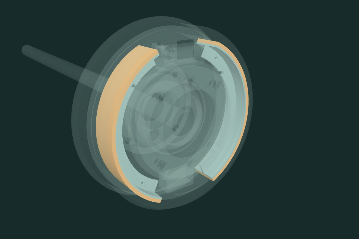
Each shoe edge extends 4 mm from the retained axial center. Four steel rim/web records and four lining records change; the other 28 mechanism records, spring eyes, expander slots, cylinder/adjuster maps and wheel-end frames stay. Both simplified rim and lining use the 32 mm envelope. Exact lining margins, edge chamfers and developed outline are unknown. The old nominal 177.8 mm radial contour remains separate from the rounded 178 mm catalog association. Radial layers, angular endpoints and installed fit remain estimates.
The current native comparison checks 120 bounded static pairs, with 22 positive contacts. Those contacts include the existing source discrepancies; see the report for before/after values. With the current fixed drum shoulder, each steel shoe/drum overlap increases from about 485.96 to 2010.68 mm³, and each lining/drum overlap from 2223.40 to 5301.02 mm³. The broader rim exposes that unresolved axial section/registration problem; no drum or shoe center was shifted to hide it. No clearance, brake adjustment, friction performance or replacement sequence follows from native validity or a catalog application.
Earlier-stage reference geometry and source contacts
The nominal drum bore remains 177.8 mm. Lining outer arcs use that contour for illustration, without running clearance or wear inference. In that earlier stage every new profile, width, slot, hole, axial station, spring shape and interface fit was estimated; the current 32 mm manufacturer width comparison is distinguished above. No new direct owner brake dimensions or fitted identities are applied. Existing photographs remain owner evidence; the previous evidence review did not establish a calibrated hidden brake-internal survey.
| Left source comparison (right mirrored) | Positive contact mm³ |
|---|---|
| left shoe front connected web rim and spring eyes / wheel cylinder two slotted piston envelopes | 24.0034 |
| left shoe front nominal contour lining / wheel cylinder two slotted piston envelopes | 0.065 |
| left shoe rear connected web rim and spring eyes / wheel cylinder two slotted piston envelopes | 24.0034 |
| left shoe rear nominal contour lining / wheel cylinder two slotted piston envelopes | 0.065 |
| left wheel cylinder hollow barrel neck and bleed boss / wheel cylinder two unloaded open boots | 395.841 |
| left adjuster open bracket and backplate neck / adjuster unthreaded square drive and conical wedge | 1.1547 |
| left adjuster front tappet and estimated wedge face / shoe front connected web rim and spring eyes | 0.8937 |
| left adjuster rear tappet and estimated wedge face / shoe rear connected web rim and spring eyes | 0.8937 |
This limited static sample covers mechanism pairs and the retained backplate. Positive contacts are reconstruction discrepancies, not evidence of damage or interference on the car. It does not certify the full axle, drum, wheel, spring or moving linkage envelope. The existing hub O-ring/gasket/shaft contacts remain documented separately in the hub study.
The offsets separate groups for inspection. They do not release spring energy, operate hydraulics, adjust shoes, establish drum/shoe withdrawal or provide a verified replacement procedure. Applicable fitted identities, handing, pressure seals/passages, loaded contacts, internal handbrake expansion, support, bleeding and adjustment procedures remain unresolved.
Native exports
Checks cover valid source solids and STEP round-trip, distinct backplate passages and source-preservation boundaries. Viewer checks cover source ownership, metric placement, bore/material witnesses, isolation and declared separation. They validate drawing consistency, not fitted brake function.
Two levers connect the handbrake to the shoes
A C-shaped primary lever now keeps the existing external rod eye and meets a separate transfer lever at a shared scissor pivot. The transfer lever crosses beneath the wheel-cylinder reference to the other shoe. Each steel shoe has an estimated web passage; a separate smooth rivet occupies the shared pivot. This replaces the old external strap and generic pivot cue. The former solid boot block is withdrawn; its actual shape and installed passage remain unresolved.
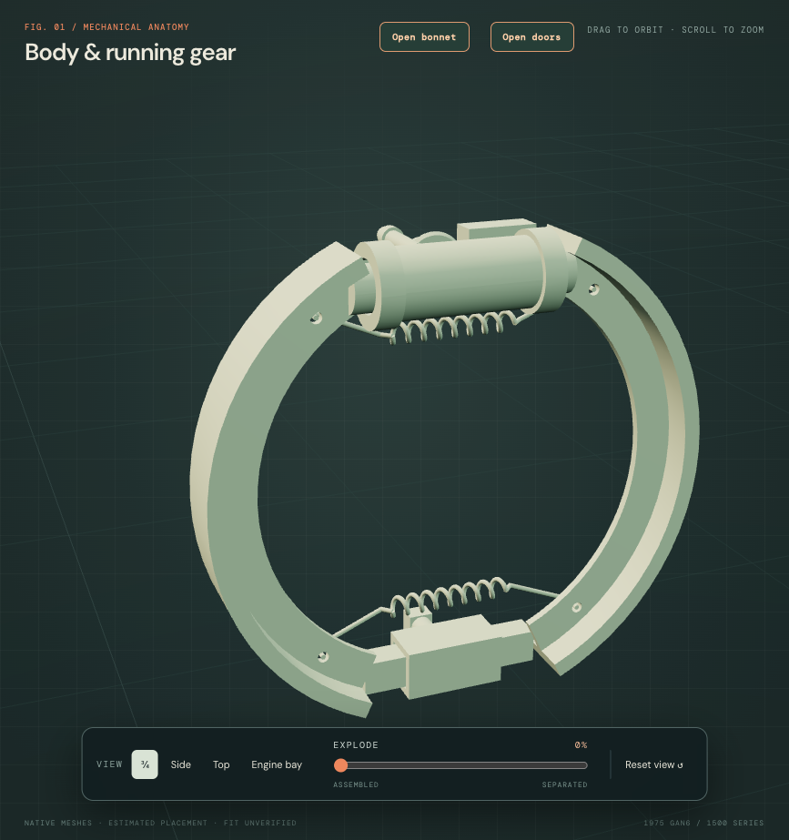
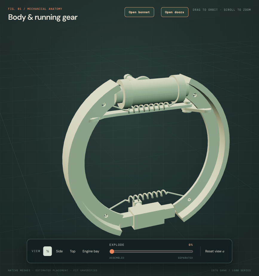
Inspect the primary lever ↗ · Inspect the transfer lever ↗ · Inspect the shared rivet ↗
The factory parts plate, p148, separates handed 17H2824/17H2825 assemblies. MGOC’s own RH and LH photographs show the two plates, rivet, eye and notches. Paul Walbran’s first-hand technical account explains the primary/secondary relationship. Its wear-repair modifications are not adopted. A workshop’s 1979 donor photographs supply assembled comparison context; they are not images of this car or a complete factory procedure.
Every new profile, gauge, pivot location, slot and notch is an estimate. Mirroring does not verify the fitted handed installation. The unchanged backplate opening is not registered to this new pose; source intersections and the spring/transfer contact are drawing discrepancies. No backplate has been cut or moved to hide them. Shoe bearing, scissor travel, loading, adjustment and withdrawal are unverified. Inspection separation is illustrative.
The cabin placement review also remains unresolved: IMG_6341 hides the control pivot and bracket; IMG_6329 hides the control. Existing camera work gives no accepted calibration for IMG_6341. There is no supported numerical correction for the control/seat/tunnel source conflicts, and no repeat owner capture is requested.