Connect the control
to both rear brakes.
The model now separates the cabin control and bracket, outer conduit, inner cable, axle support and abutment, pivot carrier, balance lever, two cross-rods and rear brake input levers. An explicit gap marks the unsurveyed body crossing. This is an estimated architecture study, with no operating brake or verified replacement path.
Inside the handbrake control
The former solid arm, filled grip and smooth sector have been replaced by an open channel and hollow grip, a separate fixed ratchet with a hollow tube, folded mounting bracket, thumb plunger, rubber washer, bent operating rod and unloaded spring. The pivot, grip end and cable eye retain their earlier reference positions; the cable and rear linkage are unchanged.
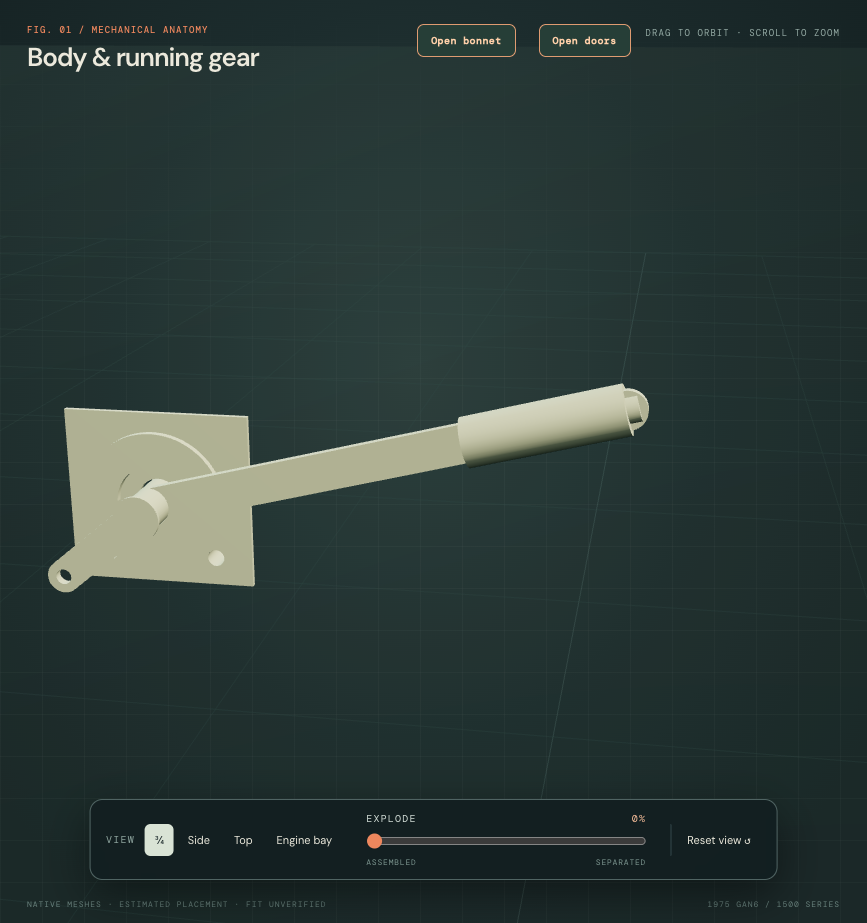
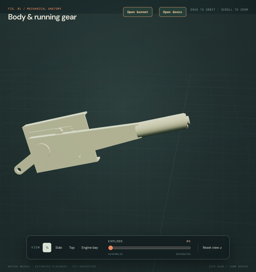
Inspect the separate ratchet ↗ · Inspect the operating rod ↗ · Inspect the plunger ↗
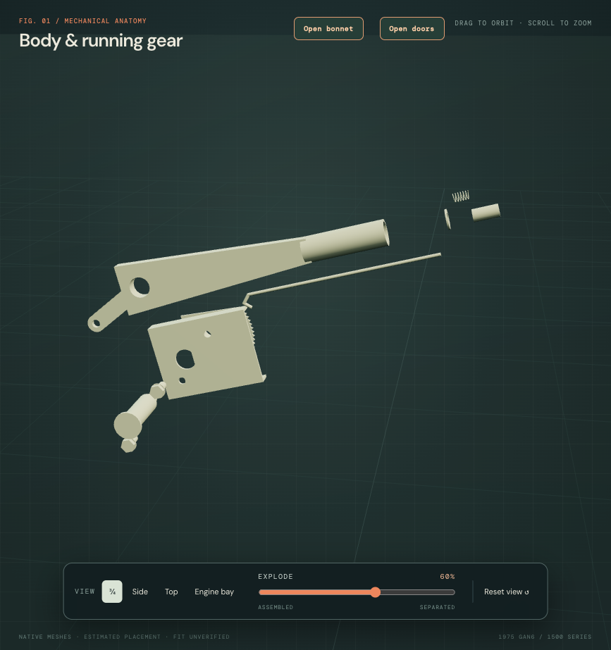
The factory parts plate identifies the separate roles. A H Spares’ manufactured ratchet photograph shows the toothed plate and hollow tube; donor control photographs show the open channel and bent rod; MGOC’s bracket photograph supports the folded-plate architecture. These comparisons do not identify this car’s fitted control.
Twelve schematic teeth, all profiles, spring dimensions, axial stacks and mounting positions are estimates. The rod ends at an unresolved pawl boundary. Actual pawl engagement, spring loading, button stroke, holding force and the AHA6406/CHA567 warning-switch branch remain unverified. The former three cubic mounting feet and body bores are withdrawn; no body drilling map is asserted.
The current lever overlaps the passenger-seat envelope by 43,307.25 mm³; the bracket overlaps it by 33,926.86 mm³. The spindle and ratchet also overlap the tunnel reference by 549.44 and 110.14 mm³. Lever/ratchet and lever/screw source overlaps remain 286.21 and 311.85 mm³. These are discrepancies between estimated model sources, not measured interference in the car. The isolated images hide those surroundings. No seat, tunnel or control datum was moved to erase the conflicts; supported cabin registration needs reconciliation before this can support fitted replacement rehearsal.
The accessible 1500 manual index lists 70.35.08, 70.35.09, 70.35.10, 70.35.11 and 70.35.16. Their operation text has not been accessed here. This study therefore supplies no factory lever removal, adjustment or cable replacement procedure. Exploded separation is illustrative.
Follow the two load relationships
The outer conduit is a separate annular reference ending at the axle abutment. The inner cable continues to a bored clevis on the balance lever. A separate carrier supports the balance pivot; its upper eyes connect to the short left and long right rod references. These relationships explain the mechanical architecture without simulating cable tension, equalization, shoe expansion or loaded support.
Keep the production branches separate
The factory handbrake plate, PDF p. 168, lists 2A7308 cable, ATA7320 support, 2A7058 carrier and 2A7057 balance lever. It separates disc-wheel BTA498/BTA497 rods from wire-wheel BTA495/BTA494 rods. This model uses the early disc-wheel arrangement as a comparison; none of those identities is verified on this car.
| Factory comparison | Boundary in this study |
|---|---|
| Early cable and axle balance lever | Topology modeled. Every fitted station, span, profile and cable/rod length remains estimated. |
| CHA638 disc-wheel / CHA634 wire-wheel cables | Factory lists the later branch from GAN6-182001. Not combined with the early compensator arrangement. |
| AHA6406 / CHA567 cabin control | CHA567 North American change is listed from GAN6-166304. Actual chassis/control identity remains unresolved; displayed hollow lever and separate toothed ratchet are estimated architecture comparisons. |
| Factory rods / modern replacement kit | Earlier factory manual describes non-adjustable transverse rods. Modern adjustable replacement rods are a separate supplier comparison, not a fitted feature added to this model. |
| Clevis-pin diameters | Supplier nominal 5/16, 1/4 and 3/16 inch comparisons explain joint sizes; modeled bores and pin envelopes are estimated allowances, not fitted tolerances or approved replacements. |
Earlier factory workshop manual M.3 and Fig. M.4, PDF p. 126, corroborates the tunnel-side control, Bowden cable, axle abutment and compensating mechanism. This earlier manual is used for architecture, without transferring its adjustment procedure or dimensions to this 1500. MGOC’s own parts listing supplies nominal pin comparisons and distinguishes cable and modern rod-kit offerings.
Owner evidence and the unresolved crossing
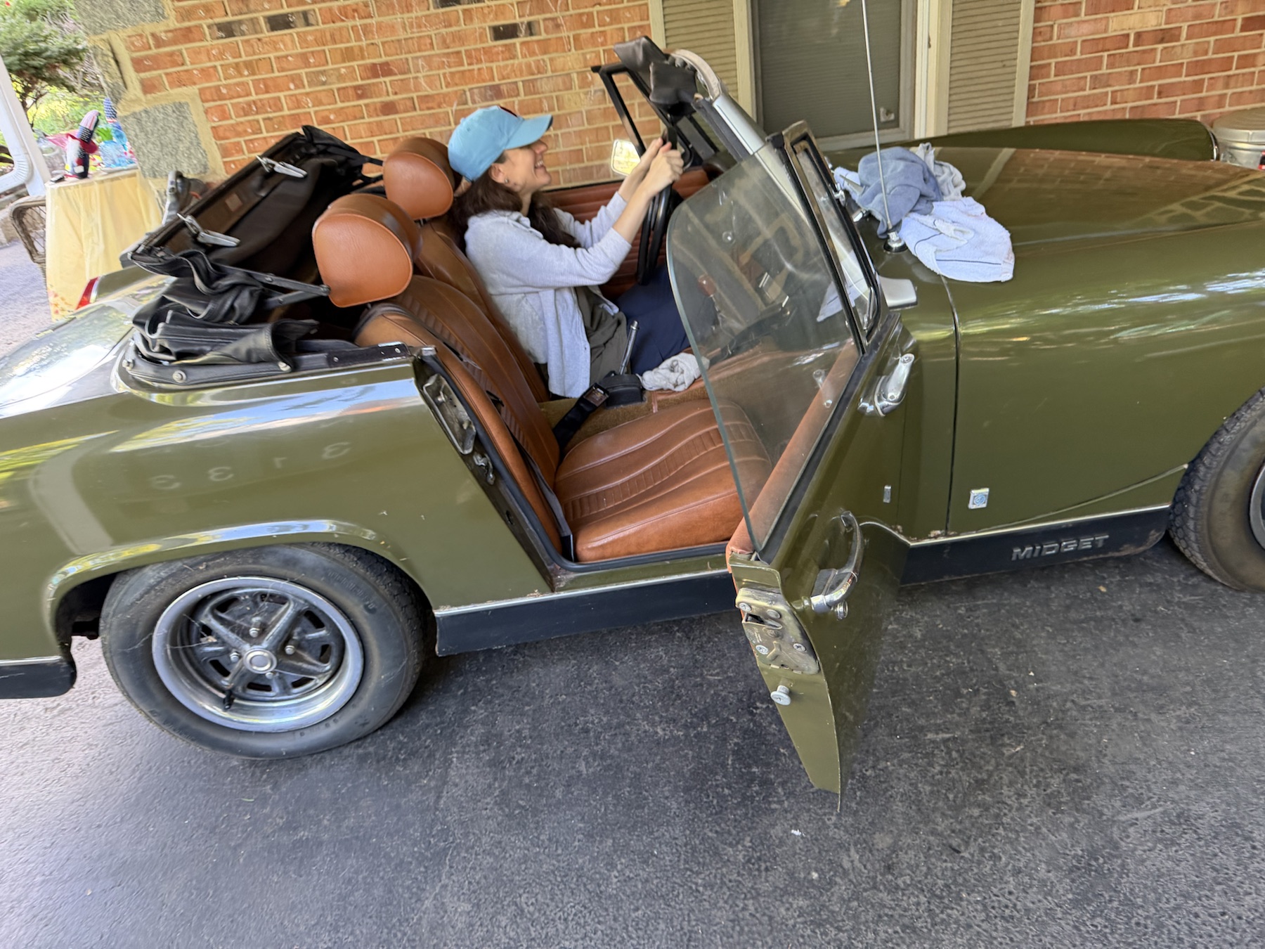
Existing owner IMG_6341 gives LHD cabin and exposed control context. It does not calibrate the hidden tunnel bracket, cable crossing, axle support or rod shapes. Existing engine-area photos and measurements do not establish those body datums. No owner dimension or fitted identity drives this new geometry, and no repeat capture is requested.
The external control-side cable segment stops above the floor. The conduit starts below the floor at a different estimated station. Their visible gap records an unresolved passage, seal, abutment and fixing relationship. Existing floor and tunnel panels are unchanged; the model does not invent a fitted opening through them.
Joined straight conduit sections, the rear approach around the axle and the rods’ rear-of-banjo doglegs are estimated construction geometry. Source-solid checks show that the conduit and rods avoid the current static axle comparison. That does not establish this car’s routing, suspension-travel envelope, exhaust/body clearance or manufactured bend radii. Rear rod-eye stations remain; the former strap, pivot cue and solid boot are superseded by a two-lever comparison. Its fitted pose and backplate passage remain unresolved.
What the workshop view supports
Use the part links to distinguish the body-mounted control, outer-cable abutment, separate pivot carrier, balance lever, rods and individual pin interfaces. Inspect which modeled joints would be involved in a component study and where the body crossing still lacks evidence. The bracket and axle support stay fixed during inspection; other groups separate for visibility.
Separation breaks the cable and rod connections illustratively. It is not a safe release order, an adjustment instruction, a loaded brake test, a verified pin extraction axis or a demonstrated withdrawal route. Verified ratchet/pawl engagement, sleeve threads, locking devices, internal shoe-expansion linkage, exact support fixings and fitted free travel remain unresolved.
Continue into the new two-lever rear expander comparison ↗
Native exports and checks
Checks cover valid solids and STEP round-trip, shared open rod/fork/lever bores, separate pin occupancy, metric viewer placement, retained native assemblies, selection and inspection ownership. Record counts measure model records, not fidelity or replacement readiness.