Open the cage.
Expose the side support.
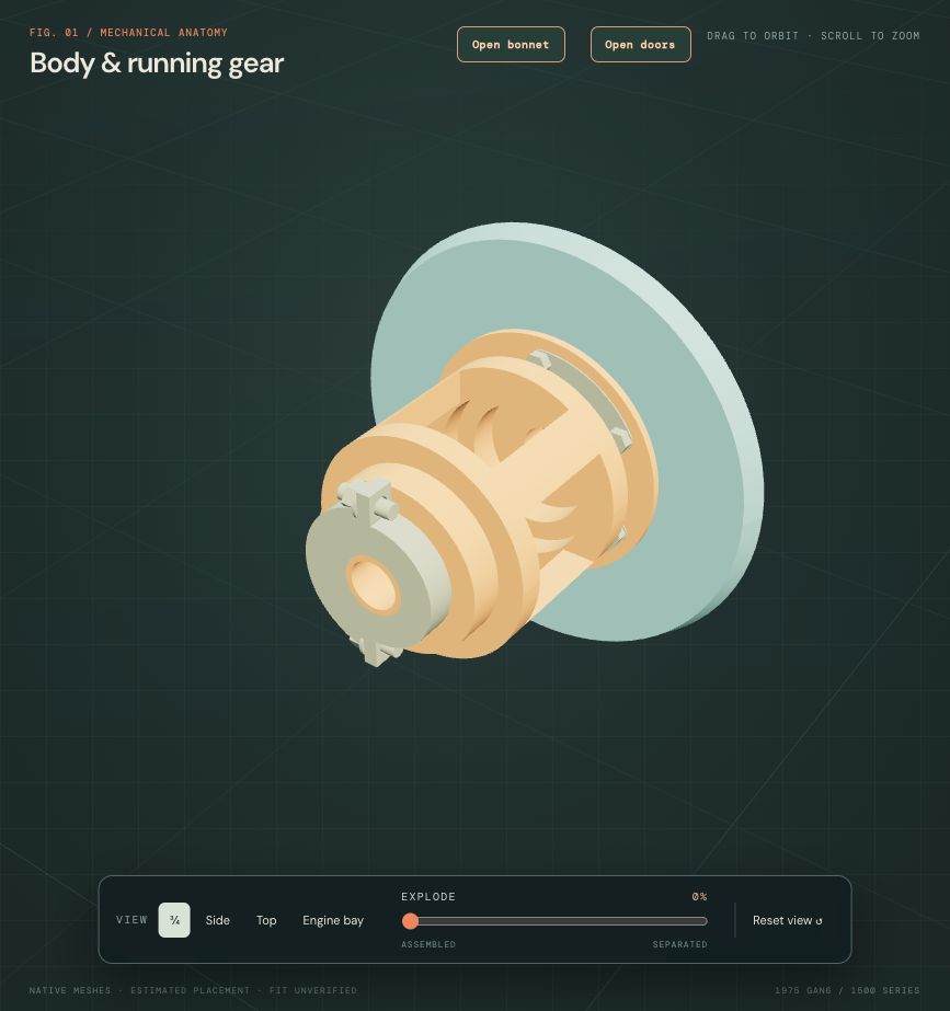
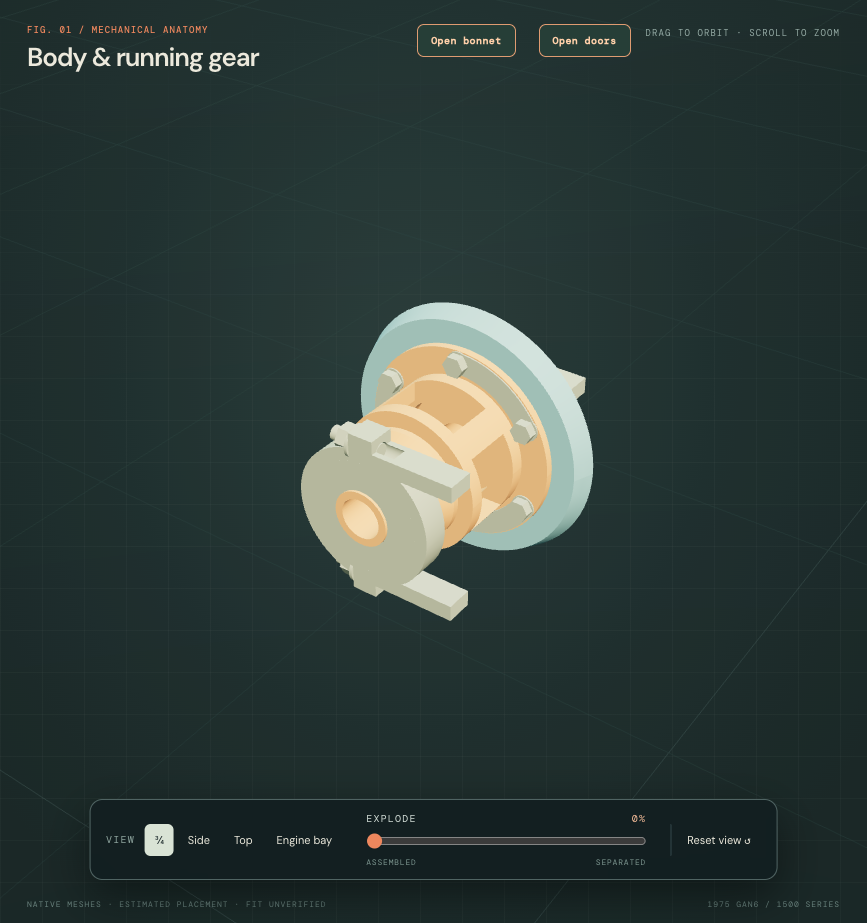
An open cage with hollow journals now carries a smooth crown-wheel boundary. Independent side-bearing envelopes sit between the cage and split carrier saddles/caps. Six crown-wheel bolts, three paired locking tabs and four cap-stud sets make the attachment roles selectable.
Inspect the new assemblies
Evidence and identity limits
Factory PDF p. 146 distinguishes the cage, two side bearings, four bearing-cap studs and selected packing. P. 147 distinguishes the matched crown-wheel/pinion set, six crown-wheel bolts and three paired locking tabs. Those roles and quantities do not identify the fitted gearset, ratio, carrier or cap pair.
The SKF angular-contact table supplies an independent 7207 BEP 35 × 72 × 17 mm boundary comparison. This is not an approved 2K5943 or fitted replacement, installed orientation, contact angle or preload specification. The model contains boundary rings rather than reconstructed balls/races.
The earlier factory H.7 discussion relates crown-wheel position and packing to measured bearing and marked carrier/cage relationships. It is comparative evidence that these settings require measurements; its formulas, torque and preload are not transferred to this car. Factory packing references of .002, .003, .004 and .010 inch remain separate from the displayed unselected0.1 mm construction separator.
Construction changes, not fitted dimensions
| Relationship | Change and limit |
|---|---|
| Halfshaft / gear boundaries | Tips move from ±90 to ±40 mm, extending each source shaft inward50 mm. Toothless gear boundaries move from ±90…120 to ±40…68 mm, shortening their drawing length2 mm to make room for cage end walls. This is an unmeasured assembly correction, not actual shaft length, gear profile or spline engagement. |
| Cage / crown wheel | Connected end walls, open windows, hollow journals and an estimated six-hole120 mm PCD support the smooth gear boundary. The positive-X crown-wheel side is a construction choice. Exact teeth, ratio, hypoid contact, planet gears and cross-pin internals remain unresolved; working gear contact is not forced. |
| Carrier / split caps | Integral front saddles and support arms now meet separate rear half caps. Four shared bores pass through both parts. All saddle/cap outlines, stud axes and seats are estimates. Matched cap identity/orientation, strength and bearing retention are unverified. |
| Preserved boundaries | Only carrier and two side-gear meshes change in the axle source; five others remain identical. Only the two shaft meshes change in the hub source; thirty others remain identical. Published track, wheel ends, axle tube ends, pinion support and propshaft maps stay unchanged. |
Source contacts and precise open evidence
| Static source comparison | Positive contact mm³ |
|---|---|
| differential toothless crown wheel boundary without ratio / differential carrier reference | 8670.07 |
| crown wheel / cap hardware reference | 77.8726 |
The estimated crown-wheel/carrier and cap-hardware overlaps above remain reconstruction discrepancies, not evidence of damage or interference on the actual car. They prevent any claim of fitted or operating clearance. A common measured carrier/bearing/cage frame, actual crown-wheel and matched-cap outlines, fitted shaft/side-gear boundaries and gearset identification are not established by the existing uncalibrated cabin/underbody views.
The offsets expose cage, crown wheel, bearings and caps. They do not unload angular-contact bearings, preserve a selected packing stack, identify matched caps, set backlash or provide a verified release/removal sequence. Bearing direction/preload, gear contact, torque, support and the applicable replacement procedure remain unverified.
Native exports and validation
Ten source groups contain twenty-nine valid STEP solids. Checks cover connected cage/caps, shared crown-wheel and cap bores, open shaft passages, reference bearing-seat nonintersection and exact neighboring-mesh preservation. Viewer checks cover metric placement/picking, bore and material witnesses, shaft-boundary extension, isolation and declared separation. These do not verify gear operation, loaded alignment or fitted dimensions.
A dimensioned comparison replaces the guessed mounting layout
The differential reference now has a shorter open cage, inward bearing/cap stations, a smaller crown-wheel photo envelope and a shared six-hole mounting map. The revised casing, axle center, wheel ends, halfshafts and pinion source keep their positions. The interfaces use a separately attributed replacement-unit drawing; the fitted differential remains unidentified.
Manufacturer specifications stay separate from the actual car
The QDF5K R.W.D. differential data sheet, issue01 dated17.5.05, was visually examined. It names Austin Healey Sprite/M.G. Midget and lists35 mm bearing journals,101.6 mm shoulder spacing,18.8 mm journal projections,139.2 mm overall length, a109.5 mm six-bolt circle with10 mm through holes,95.2 mm crown-wheel spigot,20.6 mm shoulder-to-crown-face distance and25.4 mm bore. These are manufacturer replacement-interface dimensions, not factory stock-cage measurements or owner readings.
The manufacturer asks users to confirm the application against that drawing. This model does not approve a QDF5K for this car or identify an ATB as fitted. The factory-style open cage remains an estimated architecture reference; no Quaife helical mechanism is transplanted into it.
In the selected symmetric drawing frame, nominal shoulders are X±50.8 mm, journal ends X±69.6 mm and the positive-side crown face X30.2 mm. Positive-side handedness is an inherited construction choice. The independent35×72×17 mm bearing envelopes remain comparisons, with0.1 mm unselected display packing outside each nominal shoulder: their inner faces are101.8 mm apart in this unloaded display. That difference is explicit and is not a fitted shim selection or bearing setting.
A separate supplier-photo crown-wheel estimate
The BTA1223 matched-gearset photograph supplies an outline comparison. Its six hole centers are provisionally calibrated with the109.5 mm replacement bolt circle. This assumes corresponding family interfaces; it is not an approval of compatibility. The photographed flange is treated as a plane, while tooth tips lie at different depths. Manual picks, perspective and that transfer limit the result.

The sampled tip positions give approximate161–172 mm diameters with a164.2 mm median in that conditional construction. The current smooth envelope uses a rounded165 mm diameter. Those values are not a fitted dimensional tolerance, a replacement specification or a measured gearset. Web/bevel sections and13 mm axial extent remain drawing estimates. No teeth, actual ratio, hypoid offset or working mesh is reconstructed.
What the new support geometry does—and leaves open
The cage journals, six mounting holes, separate bolts/flat lock-tab roles, bearing envelopes and rear caps share the new reference map. Carrier-owned front saddle regions share those cap axes. Their short arms stop at source Z60 mm, an omission boundary before the unverified casting attachment. They are not separate detachable parts or proposed physical cuts. The native source nearest-distance to the exterior carrier is approximately24.3 mm; this is an unclosed model relationship, not actual-car clearance.
The complete earlier260 mm gear remains separately selectable at its original shape and pose. The earlier side-gear cylindrical boundaries also retain their dimensions and stations as optional unfitted comparisons. They conflict with the revised cage and bearing layout; the validation record reports those contacts. They are not moved or reduced to create a fit. Actual sun-wheel geometry, spline engagement and placement remain unresolved.
Validation and workshop limits
The current source contains12 groups and32 positive valid STEP solids. Native probes check35 mm journals,139.2 mm overall journal length, the shared six-hole map, the open smooth bore and the165 mm gear envelope. The old gear’s native shape is retained. Cage/bearing, cap/bearing and saddle/bearing comparisons have no positive material overlap. The new cage, gear and saddle regions have no positive contact with the retained outer casing/carrier checks. These results establish the drawn reference only; they do not validate the actual assembly, bearing seating, gear mesh or operating clearance.
The three-ear housing work, external axle revision and earlier support sections remain historical stages. The prior exterior-only validation record used the earlier internal source; the current interface validation below covers the present axle/differential source combination. The next substantial priority is independent evidence for the carrier-arm attachment and actual sun-wheel boundaries. The source floor/exhaust relationship remains separate.
Factory parts roles and a manufacturer interface sheet are not a replacement procedure. No actual support strength, matched-cap orientation, selected shim, backlash, preload, torque, release order or verified withdrawal path is established. Inspection separation is illustrative.