Connect the floor
to the doorway.
Front/top folds, outer and inner sides, hinge-pillar channels and wheelhouse corner closings replace the missing body relationships around the old diagonal toe sheets. The bulkhead now has a thin section and open footwell mouths, while retaining its previous aperture datums.
What the sources establish
The manufacturer’s panel drawing and table separate rubber-bumper front/top footwells CZJ731 RH and CZJ575 LH from earlier CZJ170/171, plus outer sides AHA5620/5622 and inner toeboards 2A5550/5551. Its repair-panel catalogue distinguishes inner hinge-pillar and lower-hinge support pieces from outer A-post skins. These are component roles and application comparisons, not fitted part identifications.
Factory PDF p. 234 keeps front/inner-side footwell branches AHA8284/8285 and the AHA8860 collapsible-column comparison distinct. No replacement cross-reference or fitted column-specific panel is selected from that drawing. Owner IMG_6341 shows the open doorway and sill; IMG_6855 and IMG_6891 give rear-bay context. They do not reveal calibrated hidden pillar sections, nuts or seams.
Body platform beneath the pedal gasket
The existing pedal-box base and body gasket extended behind the old footwell roof with no body counterpart underneath most of their footprint. The left front/top panel now includes a rearward mounting platform, front step and short side returns. Its central mouth stays open for the pedal reference. The old roof is opened beneath that mouth, while its forward portion and front wall remain.
Factory plate163 distinguishes the pedal box, AHA8072 body gasket and eight base-fixing roles. It supplies architecture and quantities, not this body footprint or installed height. The manufacturer front-body drawing distinguishes front/top footwell panels. Neither identifies a fitted panel or a repair shape for this car.
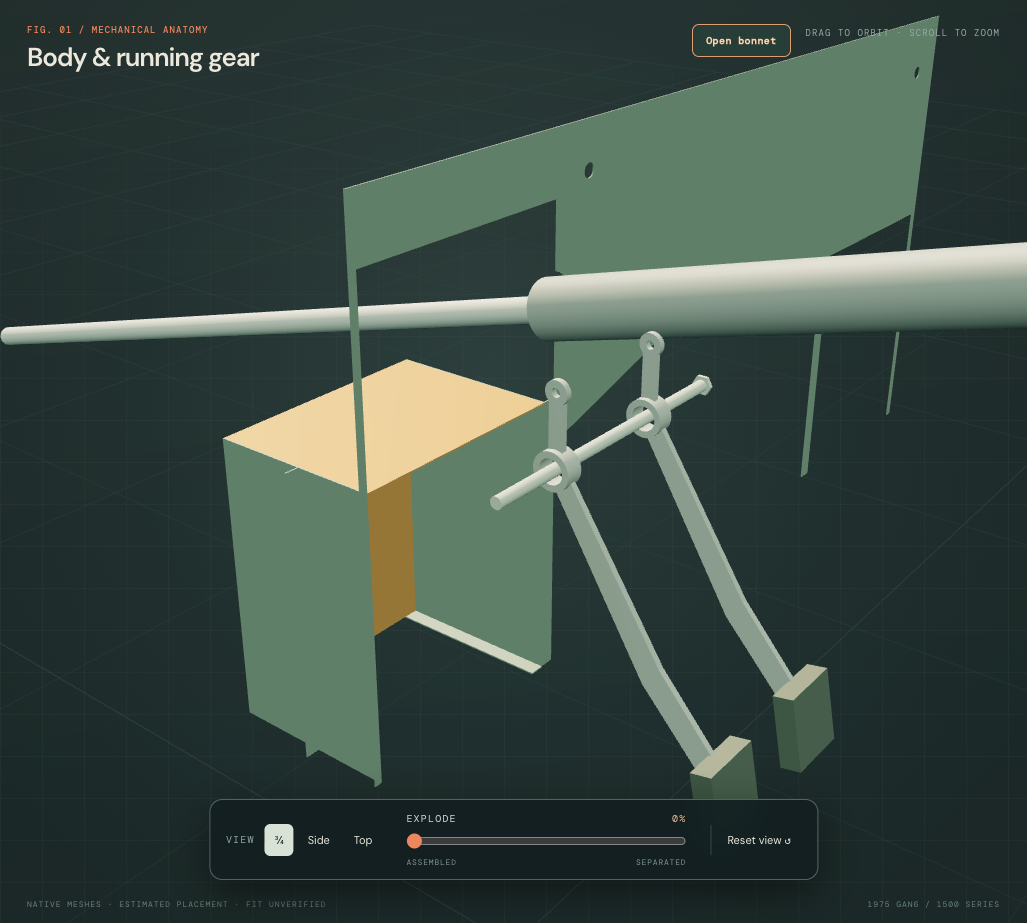
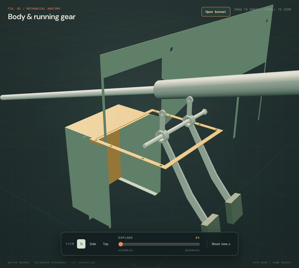
The platform projects the existing unmeasured native gasket footprint, central aperture and eight base axes into a body reference. Its top follows that gasket’s lower plane; an estimated 6.667 mm step joins the retained roof. The inherited 1.5 mm body gauge and new panel extent, folds and welded ownership remain construction hypotheses. Eight reference bores are present, but actual receiver threads, captive fittings and reinforcement are unknown. This is not a fitted hole map or drilling/repair template.
| Relationship | Current reference | What remains open |
|---|---|---|
| Pedal base / gasket / body | The new body surface meets the retained gasket plane with no positive solid overlap. Eighteen sampled gasket-material locations now have body material beneath them. | Loaded seating, rubber compression, body stiffness and actual mount dimensions. |
| Central pedal mouth | Open through the platform and the overlapping old roof region; the forward roof remains. | Actual pressing and operating pedal envelope. |
| New body / existing bulkhead and side panels | 46.50 mm³ bulkhead contact; 3.375 mm³ each at outer/inner footwell references. | Weld/lap ownership and surveyed seams; source contacts do not prove fitted joints. |
| Steering column / pedal housing and cover | Existing source geometry and registration are held; their documented overlap remains. | Common column, pedal-box and master mounting datums. No shaft kink or clearance notch is inferred. |
Only the left front/top mesh changes. The other ten footwell meshes, pedal/steering/master assemblies, accelerator, wheelhouses and cabin sources remain held. The new reference is a single connected body solid. It supplies a missing mounting-body role, with no verified structural load path, actual body alignment, safe support, release order or replacement/removal path. This body panel stays fixed in general separation.
Construction and retained datums
| Class | Applied here |
|---|---|
| Direct owner dimensions | None applied to the new panels or pillars. |
| Retained bulkhead references | Outline, rear plane Z=.13, existing left pedal aperture and wiper, wire and column aperture centers/sections. The old main sheet becomes an estimated 1.5 mm section. |
| Estimated footwell | X magnitudes .36–.66, floor Y=.35, front Z=.35, roof Y=.72, rear Z=.13 in body drawing units. Front/top folds replace the old diagonal sheets. Lower mouths join the cabin through the bulkhead. |
| Estimated inner pillar | Channel X magnitude .68–.7525, Y=.35–1.005 and Z=.153–.23. Returns and a lower foot add section behind the retained outer post. |
| Existing hinge reference | Eight backing bores match the estimated body-hinge leaf pattern: X magnitude .70, Y=.62/.91 ±.018. They are not measured fixings or a drilling template. Body and door hinge meshes remain unchanged. |
| Unresolved construction | Actual lap/weld order, gauge, box/check-strap/courtesy-switch variant, captive nuts, local repairs, corrosion, body alignment, loaded contacts and clearances. |
The outer side/jamb return bridges toward the inner-pillar channel. A closing comparison spans the lateral difference to the existing rear wheelhouse edge. Those joins are chosen architecture, without a fitted weld pattern, structural calculation or repair template. Existing floor/sill, outer A-post, wheelhouse, door and hinge reference positions are retained.
Bulkhead mouths prevent the old body sheet from closing the declared footwell volume. They do not verify pedal travel, body openings, wiring/pipe clearance or service access. Column and pedal aperture cuts can join in this estimated construction; their real boundaries remain unmeasured. Matching hinge bores do not establish a fitted hinge seat, captive-nut arrangement, door alignment or working hinge sweep.
Workshop use
Keep these welded references fixed while inspecting the separate door body hinges, pedal box and adjacent wheelhouse. Individual selection and hiding help explain the panel stack; neither supplies a safe release, cutting/welding, drilling or removal sequence. Door display separation remains illustrative.
Native export
Validation covers 25 valid solids, eight backing bores with neighboring material, open lower mouths, retained bulkhead aperture datums, metric placement/picking and fixed body inspection ownership. It does not certify fitted operation, strength, alignment or safe repair access.
Join the footwells to the tunnel
The former bulkhead had a triangular central notch around a rounded tunnel. Separate flat inner footwell walls also stopped short of it. The revised bulkhead mouth follows the existing native tunnel envelope. Paired closing shelves, front collars and upper floor lips replace those disconnected inner walls and join the retained footwell roofs/fronts and cabin floor. The existing tunnel, floors, pedal platform, apertures, hinge pillars and mechanical frames stay fixed.
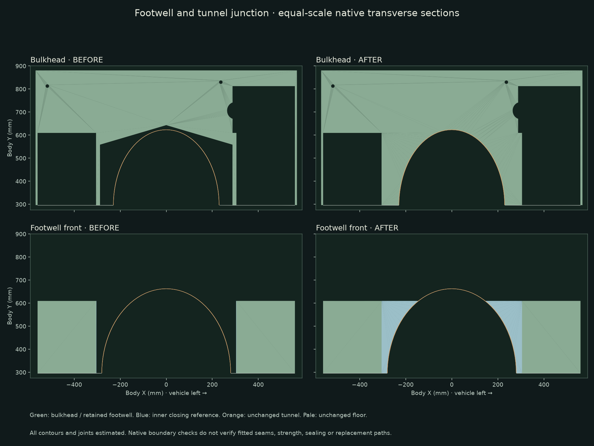
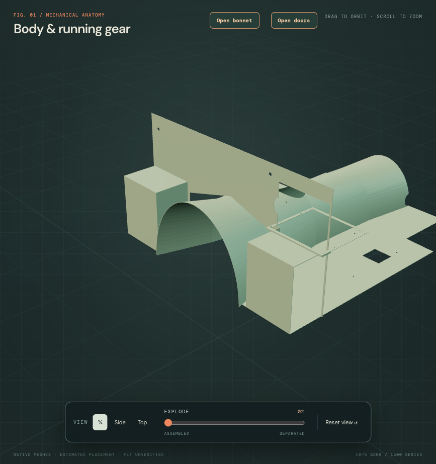
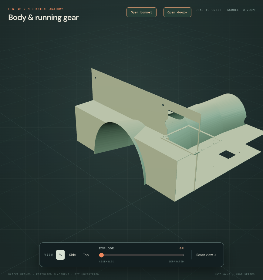
Factory plate234 distinguishes front/top and inner-side footwell branches, including the collapsible-column version. British Motor Heritage separately lists rubber-bumper front/top footwells and inner toeboards. These establish panel roles, not this car’s fitted identities, sections or seams. Existing owner photos supply cabin and rear-bay context without a calibrated hidden junction survey.
All new contours, projected 1.5 mm gauge, closing shelves/collars/lips and ownership remain estimates. Following another source’s boundary does not calibrate the actual body. The floor lip now sits above the retained floor instead of occupying the same source material below it. No actual weld/lap detail, strength, fire/fume sealing, pedal/pipe clearance or repair dimensions are established.
Native checks retain all former bulkhead material and add the closing region; eight other footwell meshes remain byte-identical. Actual source witnesses test the shared roof, front-wall, floor and tunnel edges. New closing/tunnel, closing/floor and closing/bulkhead overlaps are zero. The left closing shelf still crosses the retained pedal-plinth skirt by 177.48 mm³. That is an unregistered drawing junction, not a measured interference or a verified fitted lap.
These welded-body references remain fixed during illustrative separation. They add surrounding obstacles for studying component access; they do not establish a detachable panel, safe cutting/welding procedure or verified gearbox/pedal replacement path. The remaining plinth corner and hidden seams require fitted evidence before a physical repair or removal rehearsal can be trusted.
Give the front rails a body passage
The previous floor, bulkhead and toe-closing sheets crossed the hollow front-rail sections. Those sheets now stop at the retained rail outer envelopes. Rail geometry, seat bores and the body, engine and suspension coordinate frames stay fixed.
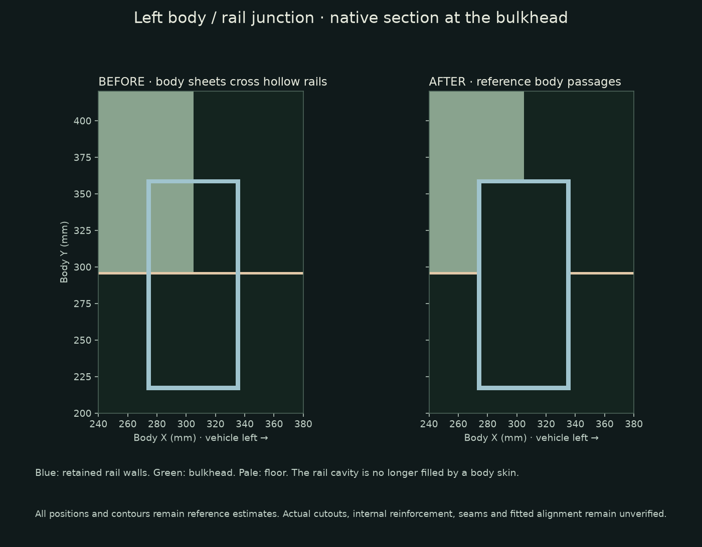
Factory plate 234 and the BMH panel register distinguish the body-panel roles. Firsthand BMH assembly photographs, especially image Y, show the rail/body joining context. They supply architecture, not the passage dimensions used here. Existing owner photographs provide surrounding context without a calibrated hidden-junction survey.
Actual laps, internal reinforcement or diaphragms, flanges and panel ownership remain unknown. Some closing surfaces are now separate fixed pieces within their inspection groups; this does not identify a physical panel count or detachable repair parts. The new passages supersede the earlier tunnel-junction study’s local skin continuity assumptions. No fitted alignment, structural strength, sealing or verified removal path is established.
Native checks cover seven changed meshes, thirteen retained mesh payloads, eight retained seat bores and unchanged rail geometry. Display-mesh volumes match their native solids within 0.1%. Source skin/rail overlaps are now zero by construction; that is not a clearance measurement on the car. Earlier reports describe their stated historical baselines.