Give the suspension
its surroundings.
The old semicircular sheet is replaced by an inner valance, a broad top with sloping end regions, a separate outer arch closure, an outer-wing return and a supporting web. These body references stay fixed while nearby parts separate for inspection.
Panel architecture, with application branches preserved
British Motor Heritage’s manufacturer drawing and application table distinguish the 1974–79 rubber-bumper inner panels BMH8022/23, supporting webs BMH8024/25 and complete assemblies CZJ682/683. The shared top and outer sections are separate items. Earlier chrome-bumper inner panels, webs and complete assemblies remain unselected comparisons. None of these numbers identifies a fitted panel on this car.
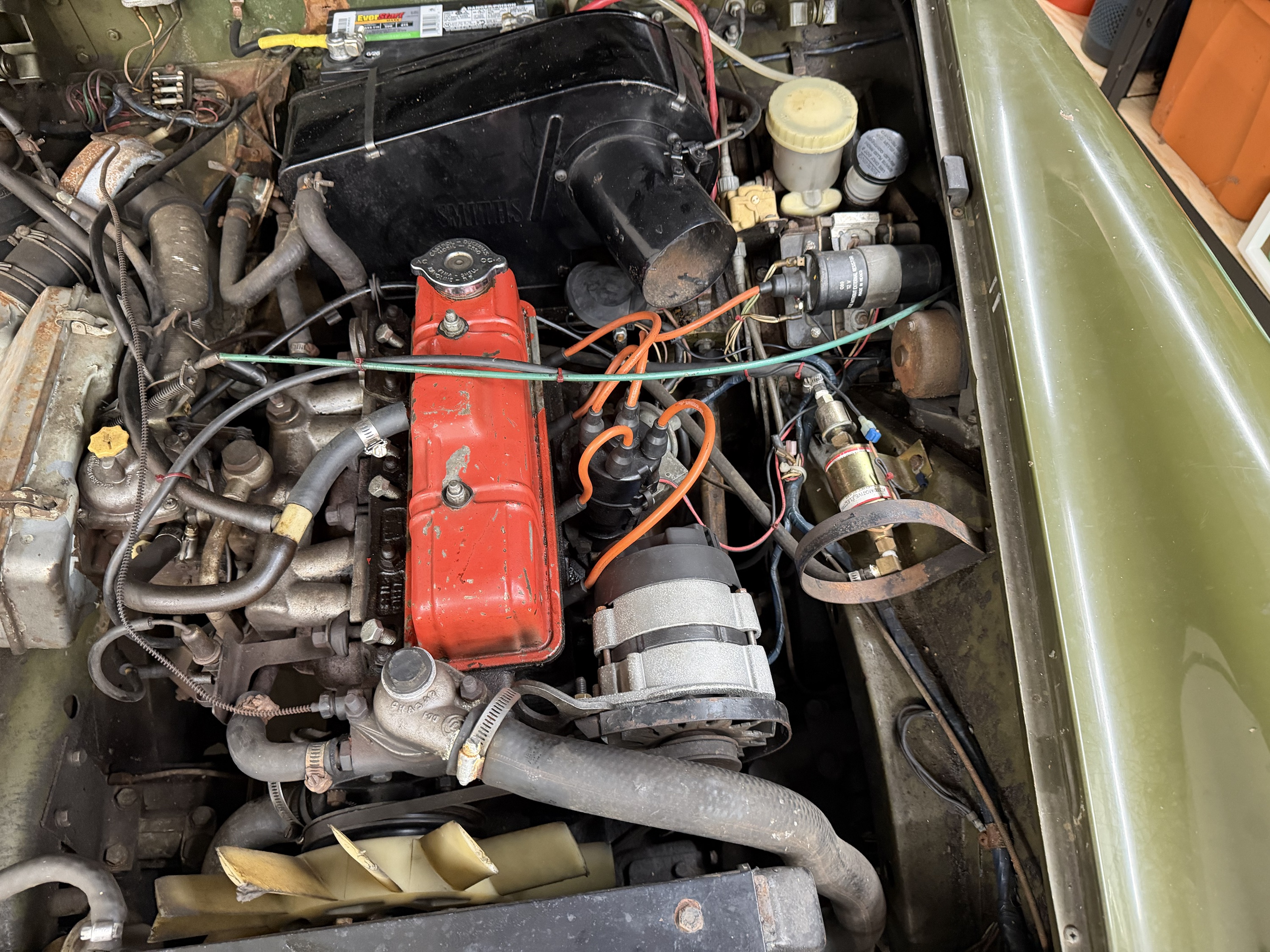
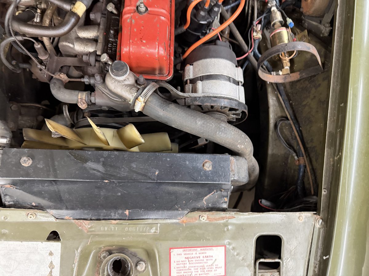
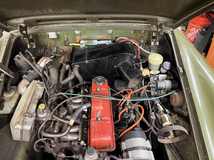
The drawing supplies the broad top, sloping ends and separate inner/outer walls. IMG_6855 and IMG_6853 show the engine-bay sheet metal and outer-wing/landing-panel context; IMG_6891 and IMG_6914 add rear-bay and underside relationships. These are uncalibrated views. Hidden seams, repairs, gauges and complete supporting-web geometry are not established from them.
What changed geometrically
The old inner wall and a zero-thickness half-cylinder were grouped together. The new inboard wall has a declared lower mouth around the existing damper, spring-support and steering-reference region. A thin top spans to the outboard closure, with sloping front and rear regions and an inboard return. The outboard panel carries the old wheel-opening arc. A continuous outer return indicates the boundary toward the separate bolt-on wing; no fixing holes or captive nuts are invented.
| Evidence class | Current construction |
|---|---|
| Owner measurements | None applied to this wheelhouse. Photos supply context without calibrated hidden geometry. |
| Retained drawing datums | Inner/outer X magnitudes .48/.69, opening center Y=.39/Z=1.20, radius .38 and top crown Y=.88 in body units. These are prior estimates. |
| New estimates | 1.5 mm sheet sections; top Z/Y profile (.35/.58), (.75/.88), (1.47/.88), (1.83/.50); inboard return to X magnitude .46 and outer-wing return to .72. No actual folded joint or lap order is established. |
| Lower mouth | Z=.90–1.55, Y=.35–.74. This is declared construction around retained references, not an identified factory aperture or a verified tool/travel allowance. |
| Supporting web | Chosen Z=.72 plane, from the retained outboard/top rail corner toward the valance. Profile, gauge, position and attachment are estimates; no strength or fitted load path is established. |
The roof-to-opening-crown station difference is a drawing construction, not minimum tyre clearance. Static open passages do not establish steering lock, suspension travel, body alignment or replacement access. The footwell/inner-pillar reference now adds front/top, side, hinge-backing and rear wheelhouse corner relationships. Their fitted seams and the remaining end-closing interfaces are still unverified. Existing electrical, heater, engine and suspension references are not surveyed together with these panels.
Close the upper bay-side strip
IMG_6853, IMG_6856 and IMG_6857 show continuous sheet metal along the upper outer bay boundary. The earlier reference stopped its wheelhouse return well below the modeled upper wing edge, leaving an empty strip. An estimated closing face now joins those existing boundary curves on each side; wheelhouse roof, outer wing, wheel opening and suspension stations are unchanged.
The manufacturer drawing and application register distinguishes wheelhouse inner/outer/top and wing attachment roles. It does not identify this closing face as a separate factory panel or establish its seam, lap, fold depth or ownership. The new face is a reconstruction hypothesis between unregistered surfaces, with an estimated 1.5 mm projected X gauge and an assumed mirrored opposite side. It is an obstacle reference, not measured fitted geometry or a repair template.
Inspect left bay closing reference ↗ · Inspect right reference ↗. These groups remain fixed for inspection. Their display ownership does not establish whether the actual return moves with a wing or remains on the welded body; no replacement/removal path is verified.
The left top now includes one estimated receiver bore shared with the owner-photo pump mounting reference. IMG_6898 supports a fastener-on-painted-ledge role; the reference axis and bore are unmeasured construction coordinates, not a factory drilling map, fitted support or repair instruction.
Use in workshop studies
Keep the body references visible while inspecting the damper, upper trunnion, kingpin and outer wing. Body groups do not translate during general separation. Selecting or hiding an individual sheet helps inspect its architecture; it does not make a welded panel removable. The outer wing’s display translation remains illustrative, without an identified fixing map or verified withdrawal route.
No cutting, drilling, weld pitch, repair alignment, spring release or safe replacement procedure is supplied. A faithful rehearsal still needs fitted component/body registration and an applicable verified service sequence.
Open the support and shape the access mouth
The four supplier views of the rubber-bumper left wheelhouse show a broad triangular support with a large rounded opening and folded edges. They also show a stepped, rounded inner-valance mouth. The manufacturer drawing and application table distinguish BMH8024/25 support roles from earlier alternatives. The previous narrow solid triangle and full-height rectangular mouth do not express that topology.
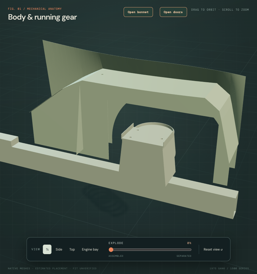
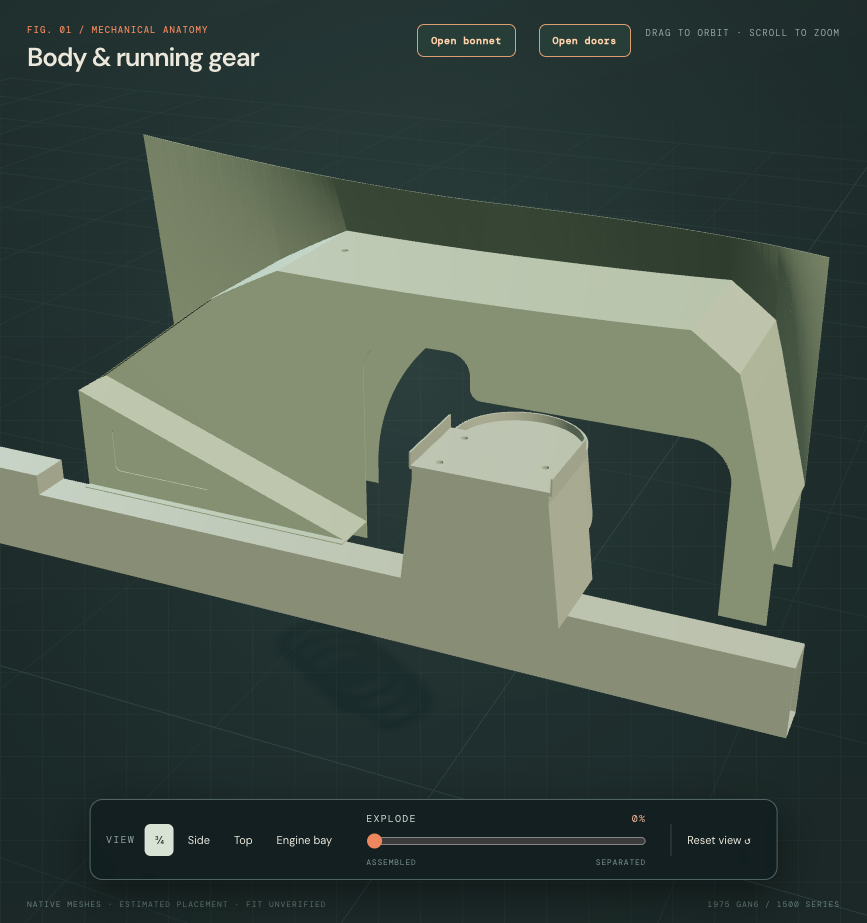
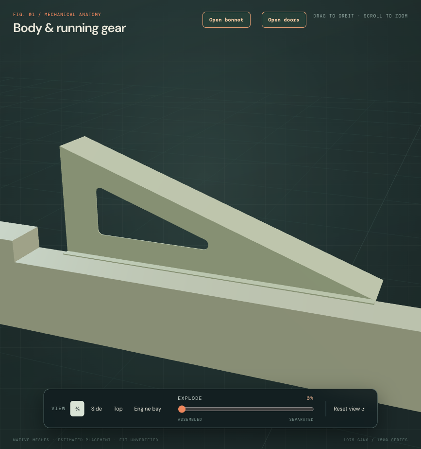
The longitudinal support spans estimated Z=.35–.90 beside the retained rail edge. A lower return meets the rail top, and an upper folded face reaches the inner valance. The web plane, span, triangular opening, 8 mm corner radii, 12 mm bottom return and projected 1.5 mm sections are chosen construction. Firsthand assembly photos support the connection interpretation without measuring its pose. The old transverse support fields remain labeled historical in the export.
The mouth retains its former outer bounds but has a smaller forward roof and a higher rear step. Its arcs and step coordinates are estimates; adding material inside the former rectangle is a topology correction, not a measured clearance. Six roof, outer-arch and upper-return mesh records remain unchanged, as do the pump receiver, running gear and spring towers.
No fitted component identity, hidden lap, weld count, repair alignment, strength or safe support point is established. The mirrored right support is an unverified construction assumption. The mouth is not a suspension travel envelope or a verified removal path. Welded body groups stay fixed during display separation.
Native export
The current STEP contains 98 valid positive solids across ten source groups. Checks cover open retained wheel-arch and declared lower-mouth regions, metric source placement and picking, fixed inspection ownership and study/download links. All other native meshes and running-gear stations are retained.
The coordinated shorter-front construction now supersedes the former forward station map. It revises the bonnet/wings, nose/lamp pose, landing/catch relationship, bumper/support beams and wheelhouse front ends together under a selected nominal length. The front-only allocation remains estimated; fitted dimensions, source contacts, support/clearances and replacement paths remain unresolved.
Continuous formed bay-side boundaries
The long lower return strips and diagonal closing web on each side are replaced by one connected formed reference. A rounded lower fold and bowed web now connect the same sampled lower roof and upper wing-edge curves. Overall bounds, wheel/access openings, pump mounting and all engine/body/suspension stations stay.
Before · strips and diagonal web
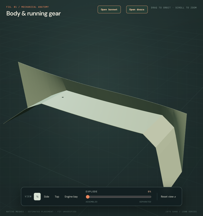
After · one continuous formed edge
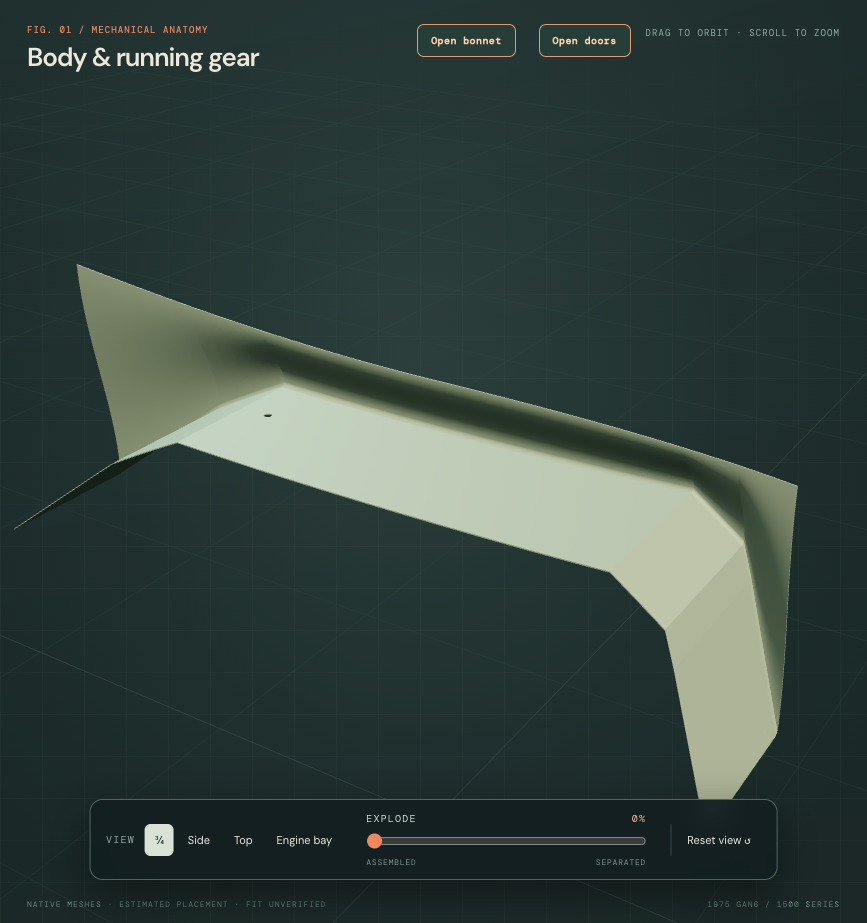
These matched diagnostic views show the left boundary and its retained roof. Other surrounding parts are hidden for inspection. The opposite side uses an estimated mirror.
Evidence and construction limits
Existing owner IMG_6853 and IMG_6856 show a continuous bay-side sheet edge. BMH distinguishes upper, outer and complete wheelarch assemblies; that architecture does not dimension this interface or establish the fitted seam.
The 6 mm lower bend, bowed section, vertical web-end tangents and 1.5 mm sampled planar-normal thickness are selected estimates. Longitudinal profile knees remain. The former projected-X closing thickness is superseded. One connected reference does not identify factory panel ownership, a welded seam, lap order or a detachable piece. No fixing pattern, captive nuts or repair template is invented.
Inspect the left formed boundary ↗ · Inspect the right boundary ↗ · Read the native checks and source contacts ↗
About 2,438 mm³ per side overlaps the outer wheelarch closure, unchanged in this scoped check. Material-point probes also confirm wing overlap on both sides before and after the change. CAD Boolean wing-volume estimates are asymmetric, so absent volume entries are not clearance proof. These reference contacts do not establish a fitted lap, seam ownership or repair allowance.
This improves the surrounding body reference; it does not resolve common engine/body registration, the clutch drawing gap, loaded clearance or an actual-car replacement path. Inspection separation is illustrative. No newly accessed factory body-removal procedure is claimed.