Separate the pump
from its connections.
The photographed electric pump now has separate exterior fittings, a bored mount foot and fixing, local hollow hoses and clamps, terminals and leads. The neighboring FLOW-marked device and metal union are independently selectable. Remote hose ends remain untraced.
Follow what the photo actually shows
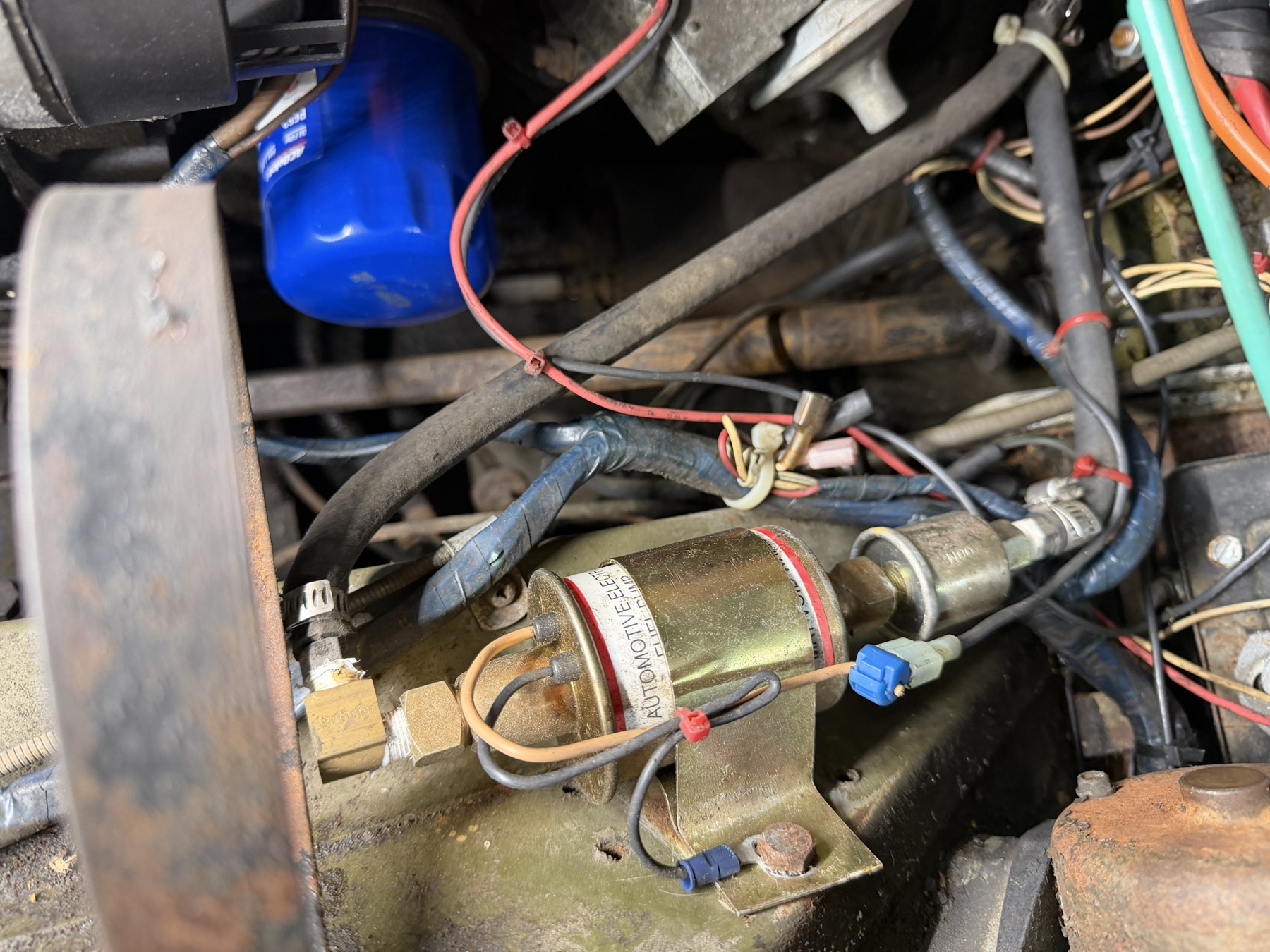
Owner IMG_6898 shows the electric-pump label, right-angle brass fitting and clamped hose at one end, the metal connection to a neighboring device, its outer hose, the pump mounting strap/foot, and local electrical connections. The model does not assign A or B as inlet/outlet and does not identify the neighboring device as a filter.
This diagram denotes physical exterior relationships only. It is not a flow diagram, a wiring circuit or a claim that the hidden internal passages are reconstructed.
Preserve the owner-car difference
Factory 1500 pump plate, PDF p. 95, lists block-mounted AC Delco mechanical pumps and separate USA/Canada pipe arrangements. The GAN6 section on p. 92 provides main/intermediate feed-pipe architecture. Neither identifies the electric unit photographed on this car.
The observed electric unit stays in the model. A mechanical pump’s continued presence, deletion, blanking, bypass or series connection is not inferred. Existing intake-area photos give carburetor context but do not establish the continuous missing hose route between these regions.
Mount the reference on the photographed ledge
IMG_6898 shows a flat pump foot and fastener against painted sheet metal. The earlier whole-car pump sat inboard and below the wheelhouse ledge. The independent pump source now uses the estimated body-axis point [520, 745.0667, 677.3333] mm on the existing left roof. Its source translation is [181, 331.3667, 49.4333] mm; this is a declared reconstruction change, not an owner measurement.
The barrel/device dimensions stay. A connected dropped web and flat foot replace the former overlapping two-solid mount whose strap extends below its foot. Foot, smooth fixing, lug and one estimated receiver bore in the left roof share an axis. Plane coincidence and open bores describe construction only: bracket folds, foot drop, receiver position, loaded support, threads and electrical function remain unverified. The original engine-only core keeps its earlier accessory pose; this independent source replaces it in the combined whole-car view.
Local hose A uses a revised Bezier estimate and hose B uses tangent circular bends to the same two old untraced endpoints. These curves do not establish the actual route, fuel compatibility, a completed circuit or removal access. Limited checks against the selected left body surfaces and coil shapes found no positive source intersections; that does not prove fitted clearance.
Inspect connected pump bracket ↗ · Inspect reference receiver ledge ↗
Retained shapes and declared corrections
| Model relationship | Basis and limitation |
|---|---|
| Pump exterior | Barrel, white label band and red-ring dimensions are retained under the declared whole-car assembly translation. The body is opaque; pumping internals, pressure specification and exact fitted identity are not modeled. |
| Mount foot / fixing | The retained-section strap now connects through an estimated dropped web to a lower flat foot, with a shared estimated 5.4 mm-radius foot/ledge bore and separate fixing/lug envelopes. No fitted body hole, support strength or electrical earth is established. |
| Adjacent device axis | Its existing body/lip shape follows the assembly translation plus the earlier -3/-6/0 mm local correction to align with the estimated pump axis and the observed metal connection. This is a declared drawing correction, not a measured installed transform. |
| Fittings / hose sockets | New elbow, metal union and outer fitting have estimated bores and socket sections. Local hoses are hollow reference bends; bore/wall, hose compatibility, seal compression, threads and clamp setting are unknown. |
| Electrical connections | Local posts/grommets and short lead envelopes show recognition boundaries. They do not establish polarity, fuse/switch supply, remote destination or earth quality. A mount lug does not prove a ground connection. |
Keep the remote ends open
The two remote hose endpoint coordinates are retained from the previous drawing. The long tank-feed pipe, rear ELC route and separate carbon-canister boundary remain unchanged and unjoined. No line is assigned to a carburetor port or tank feed merely because its photo direction appears plausible.
The elbow, union, outer fitting and hose mouths are open construction passages, but pump and adjacent-device bodies remain opaque. The model does not imply a continuous internal fluid path, filter media, pumping action, pressure/delivery behavior or an operating electrical circuit.
What the workshop view supports
Inspect the mount foot/fixing, right-angle fitting, metal union, device body, outer fitting, clamps, hose ends and terminals as separate interfaces. The mount stays fixed while other components separate for visibility. This does not provide a fuel-system disconnection order, electrical isolation procedure, thread tool size, pressure test, safe release direction or verified withdrawal route.
All added dimensions, sections and fitted relationships remain estimates. Source-solid checks cover valid geometry, open external bores, the mount passage and absence of overlap at the declared local hose sockets. They do not establish fuel compatibility, sealing, support loads, operating clearance or a replacement specification. No supplied capture is requested again.
Native exports
Twelve selectable groups use fourteen source meshes. The maintained engine export is unchanged; the whole-car viewer replaces six old pump/device source meshes and two legacy local hose curves. Other engine geometry and fuel/ELC routes remain at their previous references.