Follow the lines.
Keep the gaps.
The tank feed, rear vapor pipe and rear-bay carbon-canister comparison now occupy the whole-car reference. Short local hoses meet the observed electric-pump assembly. Open ends explicitly preserve the missing registration between these regions.
The owner car differs from the factory plate
IMG_6898 shows an electrically connected cylindrical unit whose label includes “FUEL PUMP”. The neighboring metal canister carries “FLOW” text. That establishes the pump function, but not its make, specification, flow direction or the adjacent device’s identity. Neither complete hose destination is traced. IMG_6855 and IMG_6856 provide broader rear-bay canister context.
The factory 1500 fuel-pump plate, PDF p. 95 lists a block-mounted mechanical pump. The model preserves the owner’s electric unit; it does not assume a mechanical pump remains in series or has been bypassed. The separate black carbon-canister comparison is distinct from both photographed metal devices.
Inspect the connection boundaries
The long main-feed reference ends before the pump. The rear vapor-pipe reference ends on the vehicle-left side; the carbon-canister hose has a separate open boundary on the vehicle-right. No cross-car join is invented. The two local hoses now load as separate hollow native references with the photographed elbow, union and adjacent-device exterior. Inspect the new local joint study ↗ Their remote endpoints remain untraced and are not assigned inlet/outlet roles.
Rear separator, mounting and hollow connections
Factory plate90 distinguishes the ARH302/BHH1626 vapor separator, one wing-valance fixing, tank-side pipe/hose branches, rear vapor connection and floor ferrule. The native reference now replaces the floating solid brick and buried hose endpoints with a thin hollow separator, open upper/lower ports, integral bored lug, single spacer/fixing comparison, hollow tank-side connection and hollow pipe to the retained open front boundary.
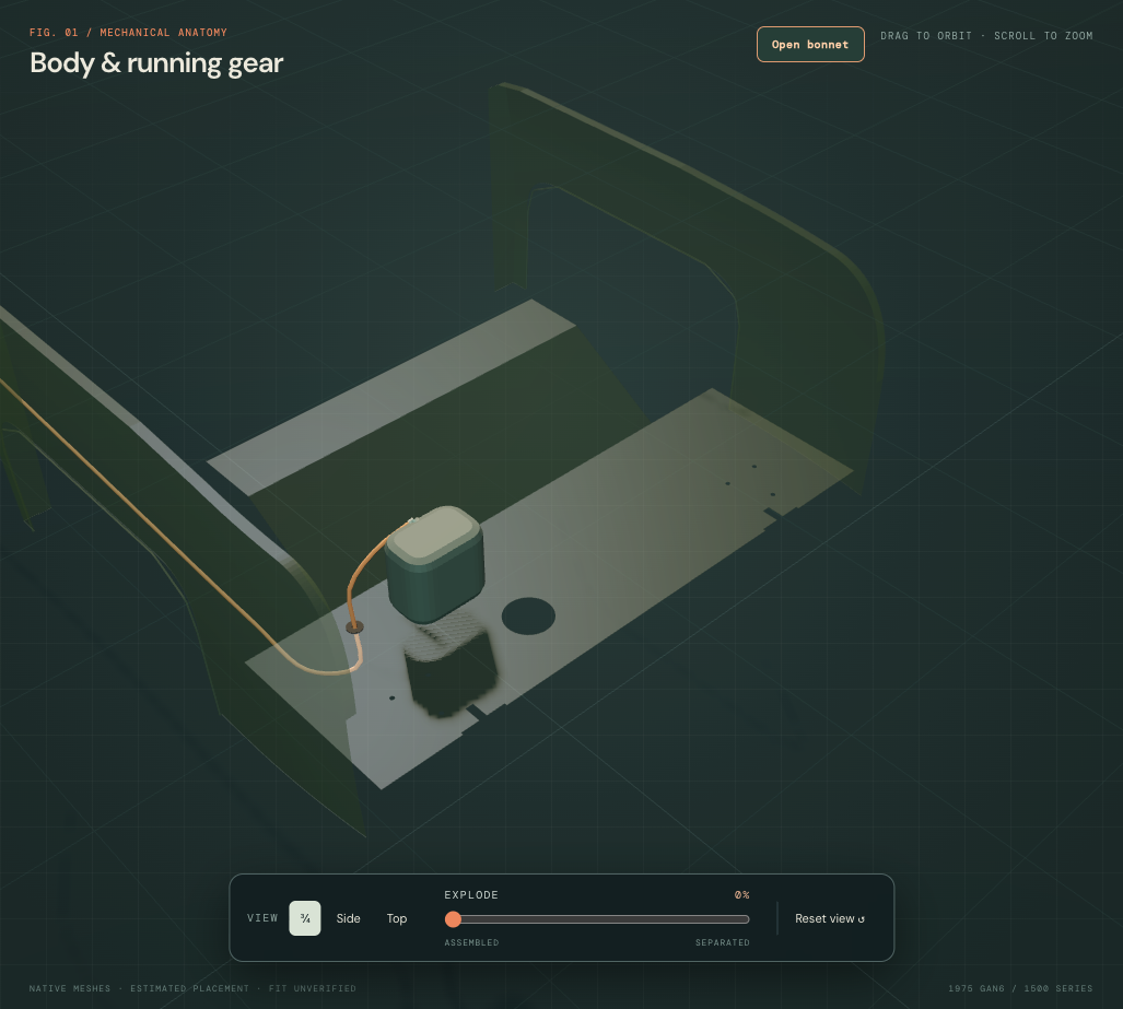
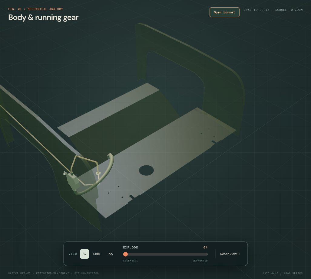
The separator’s outline, 24 mm depth, 1.2 mm wall, ports, selected Y/Z stations and quarter-relative 4 mm standoff are unmeasured construction choices. Its single lug shares a proposed axis with the spacer and smooth screw/washer/nut roles. No body receiver hole or hidden reinforcement is created. Positive contact at that reference mounting does not establish fitted seating or strength.
The tank-side taper follows the retained unregistered tank neck and an estimated 8 mm separator port, with unloaded radial display allowances. It does not select the factory pipe or hose branch. The manufacturer tank photograph shows a small port near the filler; the existing generic tank port coordinates and size are explicitly not a reproduction of that product or a fitted-car port survey. Its 138.13 mm³ floor contact remains unresolved. No port is moved and no floor opening is cut to force a fit.

The forward comparison now has an open 6 mm bore inside an 8 mm outside diameter and estimated 12 mm tangent bends. The last five route stations and front endpoint stay. The separate canister hose is still about 860 mm from that front boundary; no join or complete circuit is inferred. The existing floor passage stays at its old construction axis. A grooved unloaded grommet follows the floor sheet above and below its waist, replacing the old full annulus through the sheet.
| Selected native comparison | Current result | Limit |
|---|---|---|
| Pipe and grooved grommet / floor sheet | No positive solid intersection | Only the retained estimated opening and sheet are checked; this does not verify the passage through other body layers. |
| Mount lug / spacer / fixing against quarter | 1.20 / 12.66 / 37.30 mm³ source contacts | Quarter receiver and loaded mounting remain unknown. |
| Tank-side connection / rear bumper beam | 665.10 mm³ source contact | The new estimated route and independent beam are unregistered. |
| Forward pipe / grommet against rear bumper beam | 32.99 / 778.30 mm³ source contacts | The inherited passage conflicts with another body layer; no fitted clearance is established. |
| Grommet / damper-support panel | 34.85 mm³ source contact | Shared body-layer evidence remains incomplete. |
All seven new source groups have positive valid geometry; their selected internal solid intersections are zero. The separator cavity, port bores, connection ends and pipe bore are checked with adjacent wall material. Tank, floor, quarters, supports, filler, exhaust, cabin and selected seat/hood sources stay unchanged. These checks cover static reconstruction geometry only.
Displayed separation breaks construction joins for inspection. It does not reproduce hose release, clamp operation, safe support, a verified disconnect order or an extraction path. No internal baffles, vapor/liquid behavior, fuel compatibility, purge operation, electrical circuit or actual installation is validated. The owner’s observed electric pump remains a distinct documented difference from the factory mechanical-pump comparison.
Factory architecture, estimated geometry
PDF p. 90 separates tank, sender, vapor separator and the AHA9653 vent-pipe floor seal. A separate estimated vent opening and grommet now pass through the rear boot-floor reference; no sender access hatch is implied. PDF p. 91 lists the GAN6 carbon-canister comparison, 13H8511, and its supports. This is not a fitted part identification.
The GAN6 section on PDF p. 92 lists an 81.5-inch main-feed pipe (2070.1 mm). Its stock length is documentary evidence, not the length of the estimated viewer curve. Earlier GAN5 twin-carburetor and head-cover connections on these plates are not applied to the 1500. Purge/control branches remain unresolved.
Every new route, diameter, fitting, mounting shape and opening position is estimated. Local hose endpoints use the existing native source placement, which is itself unregistered to the body. These curves are not fabrication templates. They establish no fitted clearance, pressure rating, sealing, wiring, disconnection order or verified removal path. General separation remains illustrative.
The native tank/sender study now replaces the solid tank and coarse sender with a hollow shell/flange/neck/seat, separate sealing/locking parts and six mounting comparisons. Source contacts with the independent rear structure and the flange/floor gap remain unresolved; no fitted tank identity, circuit or removal path is established.
The current tank-side pressing comparison keeps the filler, vapor and main-feed datums fixed. It changes the pan surface only and supplies no missing pump or vapor connection.
Give the tank feed a separate interface
The factory pipe plate, PDF p. 92 / printed 107-D12, lists 37H7148M tank-to-intermediate-hose pipe, ACA5128 nut and ACA5129 nipple/olive for GAN6-154101 onward. MGOC’s 1500 listing specifies the nut and olive for ¼-inch pipe. The new hollow native pipe uses that nominal 6.35 mm outside diameter, with estimated 4.35 mm bore and 20 mm tangent bends. This is a replacement-interface comparison, not a measurement of your fitted line.
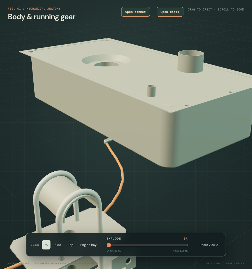
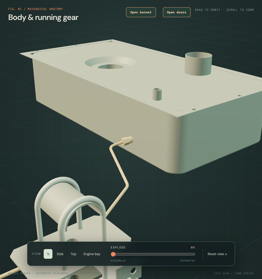
The old feed X/Y station is projected to the estimated tank front wall; its previous routing corner remains about 64 mm forward of that wall. A separate hollow receiver, smooth stepped nut and unloaded olive make that constructed interface inspectable. Receiver retention, port location, bore/hex/length, thread and sealing geometry remain estimates. The tank gets only the shared reference opening; its envelope, sender and mounting geometry stay. No internal pickup tube or strainer, fitted weld/braze, compressed olive or actual sealed joint is established.
The inherited main-route corner stations and open front endpoint stay; tangent arcs supersede the earlier viewer spline. The source centerline is about 1856.4 mm. The factory’s 81.5-inch / 207.07-cm pair is recorded without forcing the route to either value; those printed units differ slightly on conversion. No pipe cutting pattern, material suitability, clip map or loaded clearance follows.
At local commit 72944dd9, the main-pipe reference overlapped the former long upper locating web by about 74.7 mm³. The subsequent factory/supplier-based common plate revision replaces that profile while holding the pipe and joint datums. The revised source has approximately 1.21 mm separation. Neither result establishes actual-car clearance; fitted registration and hidden routing remain unresolved.
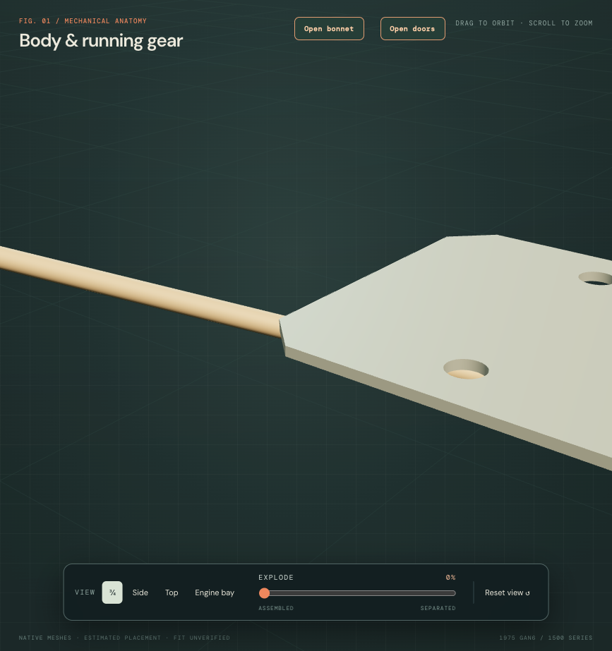
The electric-pump connection remains open
Existing owner IMG_6898 was reviewed: it supports the electric pump, local fittings, FLOW-marked adjacent device and short hoses. It does not trace either remote hose to the tank. IMG_6917 is front-underbody/suspension context, not a rear pickup survey. The pump/device/mount and both untraced hose boundaries remain unchanged. The main feed’s open front endpoint is still about 258 mm from the untraced hose-A endpoint; no connecting hose or flow direction is invented. The separate ELC vapor system remains distinct.
The factory block-mounted mechanical-pump branches on p. 95 do not establish whether a mechanical pump is fitted, bypassed or removed on this car. This reconstruction supplies no complete fuel circuit, safe disconnection/draining procedure, torque, verified replacement sequence or removal path. Inspection translations describe reference ownership only.
A native carbon-canister exterior
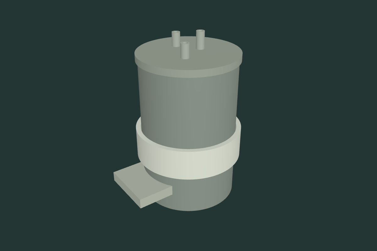
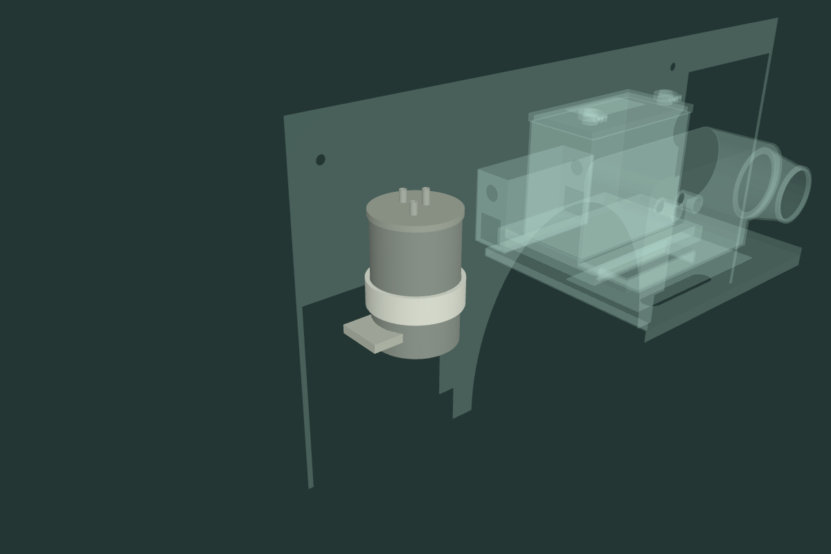
The rear-bay canister now has a native hollow casing, three-port cap, three open neck cues and a lower end boundary instead of a solid browser cylinder. The separate annular strap and two mount blocks retain the prior construction envelopes. Canister center, body radius and height, port axes/tips and all neighboring parts stay. New 2 mm wall/end sections and 6 mm bores are estimates.
Factory, replacement and fitted evidence
Factory MD0020B, PDF91 lists 13H8511 and BHH102 for GAN6-154101 onward, with a three-neck canister illustration. Its AHA9333 separate support bracket ends at GAN5-154100. The retained two mount blocks do not establish a later counterpart. AHH9658 strap remains a separate catalog role.
Engel product 201445 lists three outlets and North American Midget 1500 application. Its own photograph is a replacement-family comparison, not a calibrated 13H8511 drawing. Opposite-end projection/ribs visible in that photo are not transferred to the held factory-top-port layout without a common orientation map. Owner bay photographs establish context only; fitted identity and the full hose trace remain unresolved.
Open inspection geometry, unresolved circuit
The named first neck retains the tank-vapor comparison boundary. The other necks have no assigned purge or overflow route. Charcoal, filter pads, baffles and internal pipes are omitted; the empty display cavity does not describe fitted contents or demonstrate a working vapor path. The lower end is an inspection subdivision, not verified detachable hardware or a vent/filter reconstruction. Body receivers, threads, sealing, clamp preload and loaded support remain unknown.
The complete export has 13 groups and 19 valid positive solids, retaining all seven rear ELC mesh records and native volumes. Six new role groups contain nine solids. Cavity, three cap bores, three port bores and adjacent material pass native checks. Across 15 internal group pairs, the retained mount cues intersect the canister wall by about 1,835.95 mm³. Across 1,854 pairs against 309 retained neighbor groups, two footwell contacts remain: about 1,150.53 mm³ with the casing and 166.89 mm³ with the lower end boundary. Gaps and intersections remain reconstruction results. No heater, battery, engine, body, rear ELC or hose is relocated to create attachment. No fitted clearance, emissions performance, fuel compatibility, safe disconnection order or verified replacement/removal path follows.