Open the tank.
Keep the gaps visible.
A hollow shell and mounting flange replace the solid tank block. Separate sender head, seal, lock ring, six body-stud/retainer sets and thin seating-strip comparisons expose the service interfaces. The independent rear structure remains unchanged.
A recessed sender seat replaces the raised boss
Factory plate90 and the manufacturer’s RO9F top photograph show a recessed sender-seat architecture. The former raised annular boss is superseded by a sloping well and annular seating floor. The sender head, seal and lock ring move together into that well; their existing dimensions and X/Z axis remain. The tank envelope, flange, necks and mounting datums stay fixed.

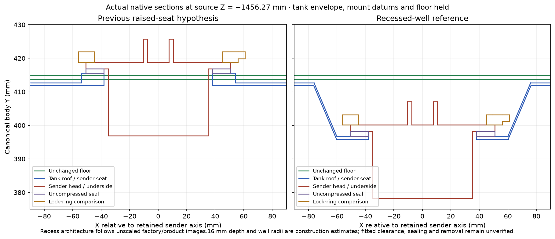
The well wall uses the catalog 0.7366 mm normal sheet comparison, with mitered profile offsets through the estimated slope. That does not establish the actual formed gauge, tool radii, seal compression or locking geometry. No capacity, float travel or gauge calibration is fitted.
| Selected source relationship | Prior raised-seat model | Current recessed reference |
|---|---|---|
| Sender / unchanged floor | 4,618.14 mm³ overlap | No positive solid intersection |
| Tank / unchanged floor | 5,687.44 mm³ overlap | 138.13 mm³, localized at the inherited vapor neck |
| Tank / suspension supports | Independent mounting references conflict | Surrounding source poses remain held; conflict unresolved |
These are comparisons of reference solids. They do not prove the actual car’s clearances or a withdrawal path. The remaining vapor port and route need reconciliation with the factory/product layout; its floor opening stays fixed. A closed floor still obstructs access from above, and the model supplies no verified release or tank-removal procedure.
Factory and supplier evidence differ
Factory ELC p. 90 separates tank branches, BRA960 sender and ARA1501/ARA1502 locking/sealing rings, including early GAN6 coverage. Earlier six-screw sender units stay separate. Non-ELC p. 89 lists six mounting nuts with plain/shakeproof washers. The supplier’s mounting description independently describes six floor-welded studs and two long/two short seating strips. That establishes a comparison mounting role, not this car’s fitted map or hardware.
The supplier’s generic narrative assigns screw-fixed senders to early 1500 tanks, conflicting with factory locking-ring coverage; its BRA960 product listing also warns that replacement tanks may differ. This study follows the explicit factory locking-ring topology as a comparison and does not select an actual tank/sender identity from age alone. No claimed capacity or sender/gauge calibration is applied.
Existing owner IMG_6329 side, IMG_6341 cabin and IMG_6919 front underside views supply general context, not a calibrated hidden rear tank survey. No direct owner dimensions are applied and no repeat capture is requested.
A documented envelope for the rear tank
The generic tank now uses a separately attributed Spectra Premium RO9F comparison: listed width 28.5 in (723.9 mm), length 14.5 in (368.3 mm), height 8 in (203.2 mm), and sheet thickness 0.029 in (0.7366 mm). Reseller descriptions instead give 15.25 in length; that discrepancy is retained. The listed 7 gal capacity is not used to fit the shape, and the page does not specify the gallon convention.
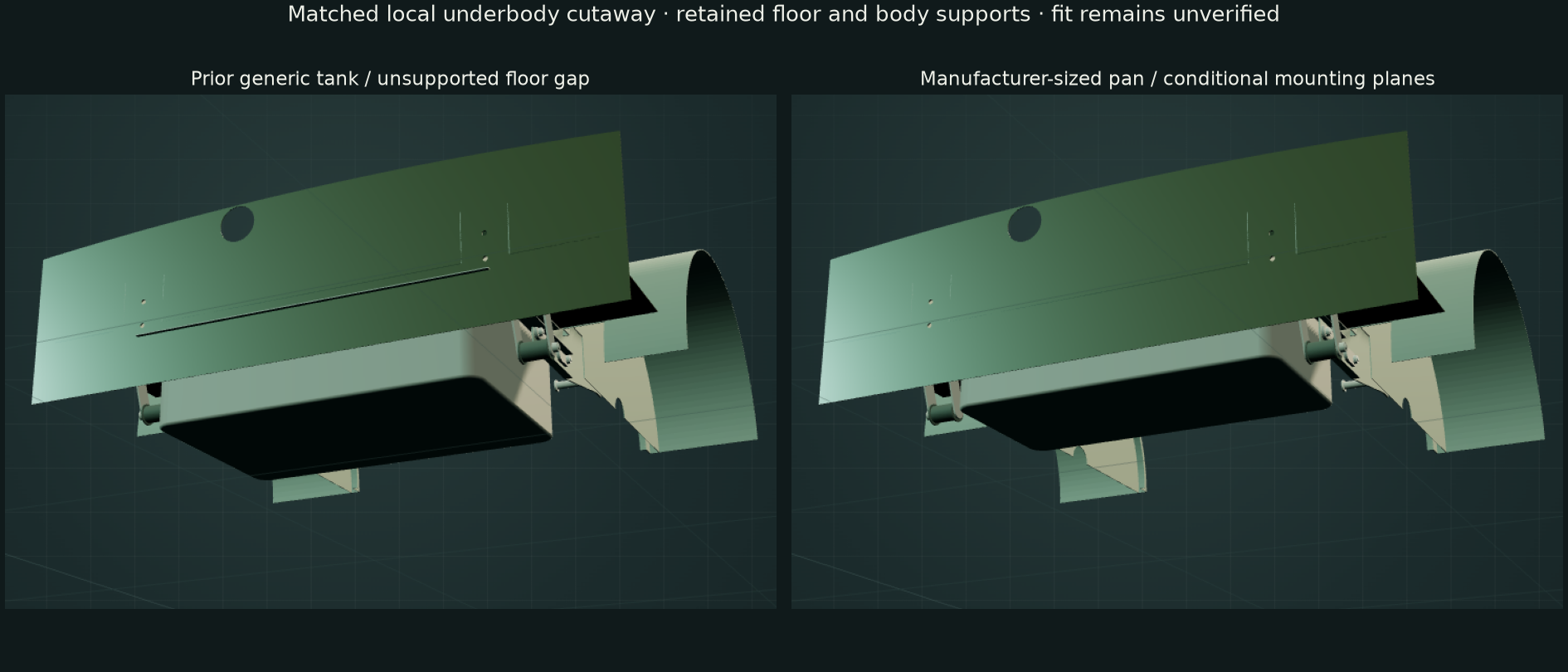
The manufacturer supplies product views rather than a dimensioned datum drawing. Applying its width/length to the flange lip and treating height as neck-inclusive are explicit assumptions. The pan/neck height split comes from an uncalibrated front-view ratio; flange overhang, seam gauge, fillets and mounting map remain estimates. This is a catalog-sized generic comparison, not a reconstruction of every RO9F pressing or proof that your car has that tank.
The revised flange sits 1 mm below the existing estimated floor underside, with the separate 1 mm strips spanning those construction planes. Six fixing axes retain their Z stations and follow the revised side flange at an estimated 10 mm edge offset. Sender/seal/lock, studs, retainers and strips follow the reference. No body receivers, new vent opening or sender service hatch are invented.
Closing the construction gap increases the tank/flange overlap with the independent shackle doublers to about 7,982 mm³ per side. The smaller plan no longer intersects the sampled bumper floor beams; other support/stud contacts remain. Body supports are unchanged. These mixed results expose missing common mounting/body-layer evidence; they do not prove fitted support or actual-car clearance. Filler/vapor X/Z and radii remain inherited unmeasured choices, and the vapor neck still crosses the independent floor away from its old hole cue.
Current dimensions, prior/current contacts and validation · Inspect tank and surroundings
What is retained and what changes
| Interface | Reference construction and limit |
|---|---|
| Tank shell / flange | The manufacturer-envelope comparison above supersedes the prior plan, bottom and 1.2 mm generic wall. Source wall thickness is separately attributed; pressing/fillet/flange assumptions, fitted identity, capacity, drain and pickup remain unknown. |
| Sender / seal / lock ring | Sender seat, plain underside/head, annular seal and ring/tool-lug comparison are separate. The old outlet-like rod is removed; two tabs are unassigned electrical envelopes, not a traced circuit. No float, pickup, locking cam, loaded seal or calibration is reconstructed. |
| Six mount axes | Six holes retain their Z drawing stations; X follows the revised flange at an estimated 10 mm edge offset. Smooth studs descend from the retained floor-underside datum; new body through-holes are not invented for the welded-stud comparison. Washer/shakeproof/nut rings do not establish a thread or actual locking. |
| Seating strips | Two long and two short strips are only 1 mm-thick reference envelopes. They now span the declared 1 mm flange/floor construction gap; the former approximately 20 mm drawing gap is superseded. They are not fitted packing, seal compression or evidence of a continuous support path. |
Sampled source-solid contacts remain with the local shackle doublers/brackets, formed damper supports and rear bumper beams. The tank follows the catalog-sized conditional reconstruction; those independent body references are unchanged and are not cut to erase contacts. These are reconstruction conflicts, not fitted interference, damage or a repair finding.
Inspect the source conflicts
| Sampled pair, per side | Intersection volume |
|---|---|
| Tank / local shackle doubler and returns | About 7,981.529 mm³ |
| Stud envelopes / local doubler | 301.593 mm³ |
| Stud envelopes / detachable shackle bracket | 150.796 mm³ |
| Tank / formed damper support | 1196.419 mm³ |
| Stud envelopes / formed damper support | 314.496 mm³ |
| Tank / bumper floor beam | 0.0 mm³ |
The export records all positive contacts from sixteen sampled pairs. A weld-base envelope touching body material is not automatically a service interference; the actual attachment and body layers are unverified. Detachable bracket and tank-flange overlaps still need a common fitted registration. The retained vapor stub also meets the independent boot-floor reference. No extra floor opening is cut to manufacture a route.
Filler connected to the revised tank reference
The earlier filler started at the superseded tank height and was partly buried in the reconstructed tank. Its solid hose and straight rod are replaced by a hollow unloaded sleeve, a hollow bent metal neck, two clamp/adjuster comparisons, a body grommet, cap gasket and closed cap shell. These seven parts separate the inspection boundaries without selecting fitted part identities.
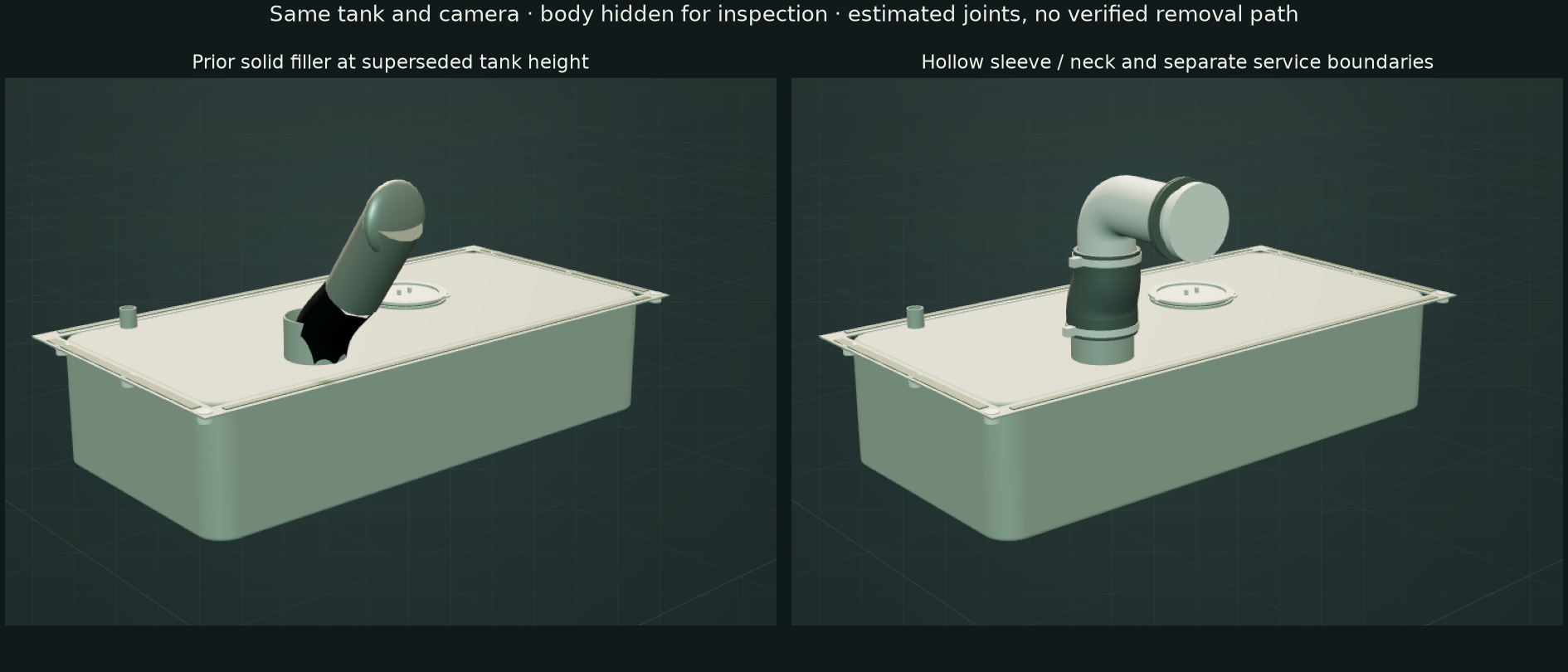
Factory page 90 distinguishes filler/neck/cap applications, including California and unleaded-fuel branches. MGOC’s component plate supplies separate connector and two-clip comparison roles. CHA452 and listed clip alternatives are documentary references; neither the fitted hose nor the clamp size is identified.
The sleeve follows the current tank spigot and a revised estimated metal-neck entry. A 40 mm construction bend leads to an outlet normal to the retained rear-panel opening. Diameters, walls, intermediate stations, clamp positions, 15 mm outlet extension, cap and grommet details are estimates. The 0.6 mm radial allowance and 18 mm axial overlaps are drawing choices, not measured clearance, fitted insertion or loaded sealing.
Selected native checks find no positive contacts between the filler parts and tank, among the seven filler groups, or against the sampled lid and rear-bumper sources. Those checks cover independent reconstruction geometry only. Body-panel/grommet seating, seal compression, hose compatibility, cap locking/venting, tool access and safe release order remain unverified. The inherited vapor neck and floor opening remain separate unresolved references. No new body holes or removal path are invented.
The original three-mesh filler remains if the native source cannot load. Body seals stay fixed during illustrative separation; offsets do not simulate real release motion or a replacement procedure.
Workshop boundary
Selection and isolation now distinguish tank, sender, sealing/locking parts, body studs, underside retainers and strips. Body-stud envelopes remain fixed in the display; other separation offsets are illustrative. The floor remains closed above the sender. No service hatch, fitted seal, safe drain/disconnection/support order, actual nut access or verified sender/tank withdrawal path is established.
The hollow filler reconstruction above supersedes the old solid route. ELC/feed boundaries remain independent references. Open tank necks do not prove a hose coupling, vapor route, internal pickup or complete fuel circuit. Fitted materials, fuel compatibility, electrical function, strength, torque, installed clearance and reassembly checks remain unverified. Applicable factory procedures and the actual installation must be reconciled before replacement rehearsal can be verified.
Native exports
Seven source meshes contain thirty-two valid positive STEP solids. Current checks cover normal well-wall offset, annular floor/open bore, six retained flange bores, separate sender/seal/lock volumes, rigid sender translation and unchanged tank bounds. Three mounting/retainer/strip meshes remain byte-identical. Browser checks verify seven groups, metric placement/picking, isolation and all72 registered source states ready, followed by a production reload without temporary hooks or page errors. They do not certify fitted clearance or replacement readiness.