Inside the
rear deck.
The solid rear-deck block is replaced by a curved surround, lid opening and separate lid. A formed floor, cockpit bulkhead, rear closing panel and existing wheelhouses bound the compartment. Seal, hinge and striker references distinguish the lid joints.
Every profile, panel offset, aperture, station, hinge axis and seal section is estimated. Existing owner side/cockpit photos show the closed rear exterior and folded-hood context, but do not calibrate the hidden boot interior. The tank, filler, sender, axle and native source models retain their existing positions. Their common fitted registration and contacts remain unresolved.
Inspect the compartment
Source panel relationships
Factory boot-lid plate 249 lists CZJ351 lid. Plate 250 separates handed hinges, lid lock, body striker, sealing rubber, buffers and lid support. CHA149 seal and AHA9716 support are catalog comparisons for GAN6; neither is identified as fitted. Native parked support envelopes now appear below; operating travel, loaded support and lock actuation remain unmodeled.
The manufacturer rear-body drawing separates formed cockpit/boot-floor sections, inner wheelarches, rear deck reinforcement and body connections. This supports the raised forward floor, transition and low rear panel as architecture. Their heights and bend locations are estimates; the drawing is not a fitted clearance specification.
What is represented
| Region | Drawing relationship | Limits |
|---|---|---|
| Deck / lid | A curved surround leaves a rounded rectangular aperture; the lid overlaps its edge in a separate selectable group. | Overlap, display gap, skin offset and contour are estimates. No hinge sweep, weather sealing or lid alignment is verified. |
| Floor / axle / wheelhouses | Raised forward and sloping panels pass between the wheelhouse planes; the low rear panel widens behind them. | The earlier flat scaffold crossed the native axle envelope. The new formed-floor reference does not establish actual clearance, ride height, suspension travel or body dimensions. The 1.2 mm floor/lid offset is vertical separation, not measured normal gauge. |
| Filler / sender | Estimated floor and rear-panel openings follow the existing filler-neck drawing. The floor remains continuous over the sender reference. | No sender service hatch is added. Openings, grommets, body/tank spacing, mounting holes and sender/floor contact remain unverified. Isolation does not imply in-car sender access. |
| Cockpit / bulkhead | A front panel separates the compartment from the existing seat references. A seat-back pivot error is corrected to retain its declared local center. | Seat dimensions, rake, mounting and bulkhead contacts remain unregistered. The pivot correction does not certify fit. |
Use as a workshop study
General separation translates the lid upward to expose the aperture while the welded compartment, seal and body-side joint cues remain fixed. Lid-side leaf and catch cues move with the lid. This is illustrative separation; it does not identify which hinge half to loosen or provide a safe supported open-lid state.
No lid removal sequence, prop position, tank withdrawal space, sender access route, safe support point, weld-cutting plan, seal compression or tightening instruction follows from this model. Spare-wheel equipment, drains, strengthening details, lamp/wiring apertures and a complete seam map are also absent. The deck surround and closing walls now have separate closed native references. The floor and aperture seal remain viewer comparisons. All STEP geometry described below is construction reference, not a fitted scan.
Rear bumper floor beams and damper/strap body supports now supplement the boot surroundings. Rear-open floor/doubler reliefs accommodate retained lower bumper-stud construction axes; they are model corrections, not observed factory openings or a cutting template.
The native tank/sender study now replaces the solid tank and coarse sender with a hollow shell/flange/neck/seat, separate sealing/locking parts and six mounting comparisons. Source contacts with the independent rear structure and the flange/floor gap remain unresolved; no fitted tank identity, circuit or removal path is established.
Rear body corrected against your side photograph
The rear quarter previously fell too far below the visible upper edge in IMG_6329. A shorter rear transition and flatter upper shoulder now feed the welded quarter skins, rear deck surround, aperture lip/seal and native boot-lid skin/frame. Hinge, handle, latch, buffers and parked-support attachment references follow that lid surface. Widths, lateral crown, lower rear point, forward shoulder anchor and axle/wheel/bumper/floor stations are retained estimates.
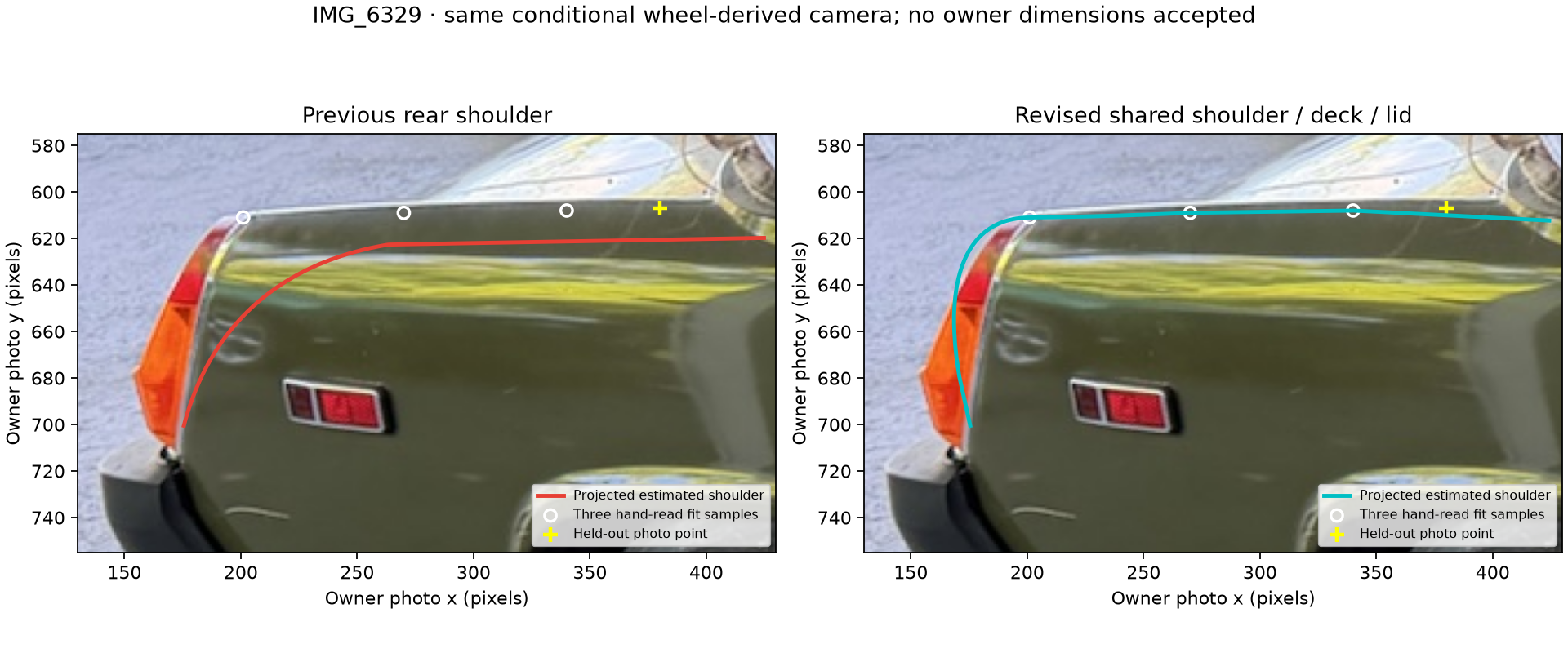
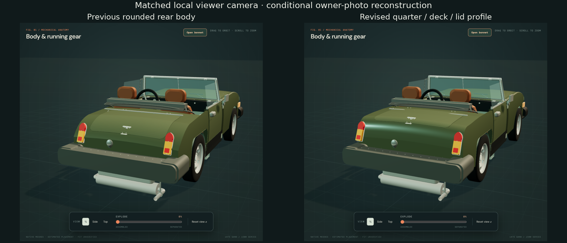
The camera remains conditional on nominal wheelbase/track and estimated wheel-face offsets. The three-dimensional body shape is not uniquely recovered from this photo. Hidden sections, fitted clearances, pressing thickness, symmetry and mounting maps remain unknown. No body receivers or lamp holes have been invented.
The British Motor Heritage panel range distinguishes rubber-bumper rear wings CZJ590/591. Its generic CZJ598 rear-panel listing is not treated as this car’s fitted panel: factory page 231 distinguishes North-American CZJ642 from the non-North-American CZJ598 branch.
The initial rear-profile revision exposed the old retainer crossing the lid: approximately 8,974 mm³ at the skin and 45 mm³ at the frame. The subsequent parked-hood revision places the body-carried retainer on the fixed shroud ahead of the lid, using an explicitly unmeasured mid-band construction station. That source overlap is now absent. This corrects the body/lid relationship; it does not verify the fitted station, attachment seating or lid clearance.
Inspect the revised lid and surroundings · Evidence and profile register · Validation scope
Rear body in the quarter-panel CAD frame
The deck surround and downturned boot lip, rear closing panel and cockpit-to-boot bulkhead now have three connected native solids in the same frame as the welded quarter references. The rear wall’s sides follow the existing quarter camber instead of the old constant top width. The shoulder/crown, boot opening, lower/front/rear stations and filler/bumper hole axes stay.
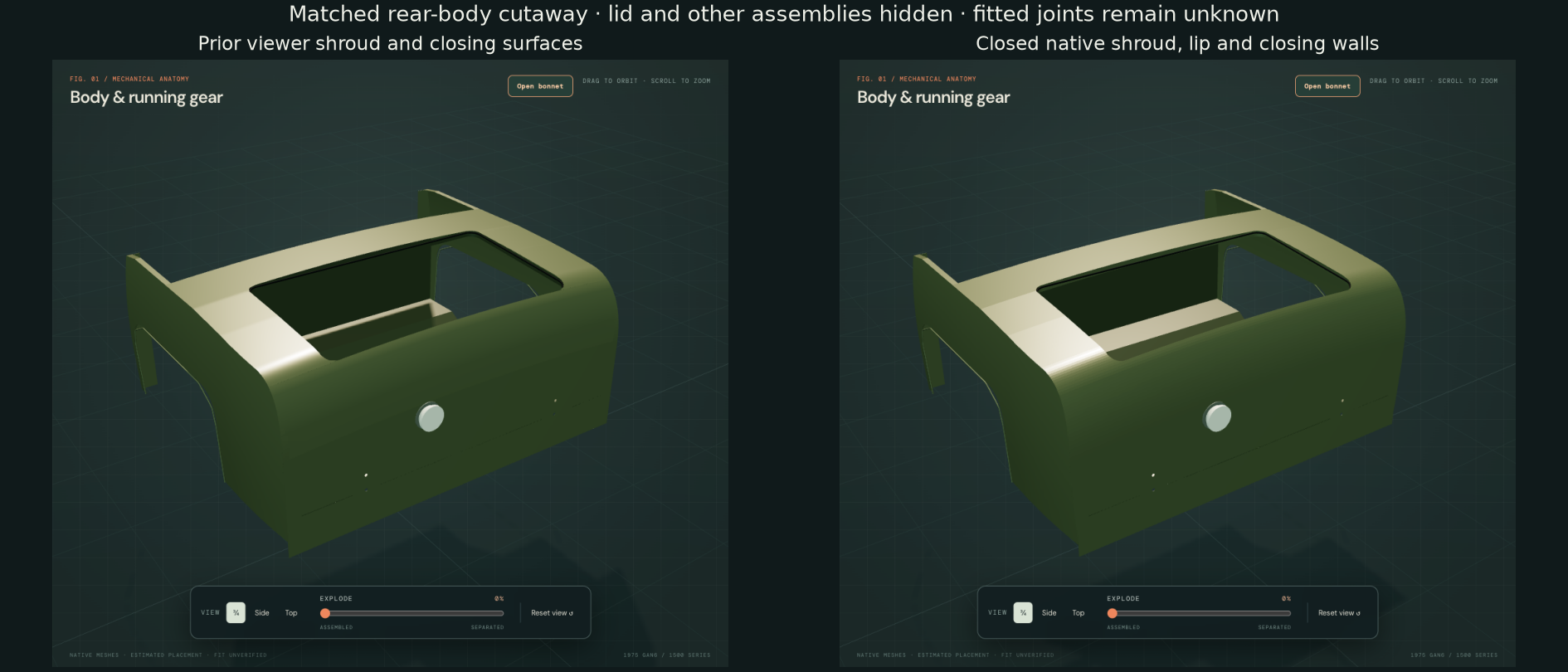
Deck and lip projected gauges follow the existing 1.2 mm skin-offset estimate; the wall offset is also an inherited reference. These are not measured normal sheet gauges. Lip depth is the retained 21.17 mm construction. The rear 18 mm and bulkhead 20 mm upper returns are new estimates. Factory and manufacturer component architecture does not establish their fitted flange dimensions, pressing identity, seam ownership or weld schedule. The North-American lower-panel branch remains distinct from the generic/non-North-American catalog panel.
New native body exposes open fit relationships
| Selected source pair | Positive volume |
|---|---|
| Surround/lip · lid inner frame, prior → current | 7,556.67 → 10.79 mm³ |
| Surround · lid gooseneck/leaf reference | 125.74 mm³ |
| Rear wall · unloaded filler body grommet | 1,452.32 mm³ |
| Surround · lamp body gasket, each side | About 603.13 mm³ |
| Surround · quarter reference, each side | About 6,442.40 mm³ |
The first rows expose unresolved lid, seal and mounting registration. Body-to-body overlap records the shared estimated joint construction; fitted layers remain unverified. The validation file also records hinge/striker/support fixing roles, lamp bases, closing-wall/quarter and internal body contacts. Existing lid, filler, lamps, quarters, tank and supports were not moved to erase these results. No new lamp receiver, hinge drilling map or sender hatch is fabricated.
The subsequent stepped-frame comparison removes the broad deep-floor/rim conflict while preserving the intended outer profile and hardware stations. Residual contact remains near the two forward hinge bosses. Other hardware and unloaded-seal contacts stay; fitted closure, layers and mounting dimensions remain unverified.
Joined floor and previously missing side extensions
The low rear floor, sloping transition and raised forward floor now form one connected native sheet reference. Separate left/right outer extensions fill the former gap between its retained rear edges and the quarter interiors. Their upstands follow the existing quarter construction. Factory PDF233 lists the GAN6 CZJ569 luggage-floor assembly and AHA5837/5838 extensions. Manufacturer printed64–65, PDF33 separately lists the side extensions and CZJ568 floor/CZJ602 rear-underframe assembly comparisons. Those catalog identities remain distinct; none identifies the actual fitted panels.
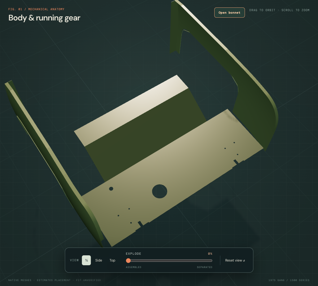
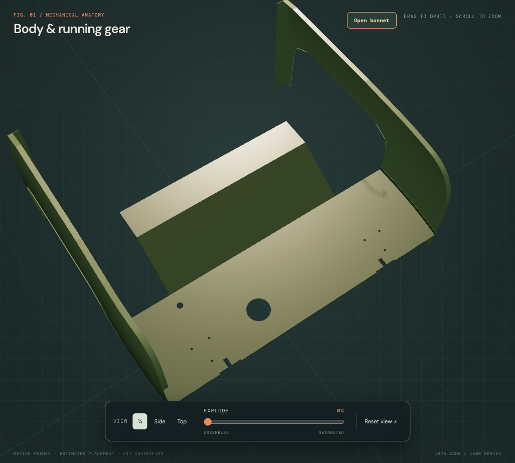
Existing floor top heights, bend stations, filler/vent openings, six shackle bores and two rear-open bumper reliefs are retained. All are unmeasured construction. The 1.2 mm projected floor/return gauges and new 16 mm outer return are estimates. Panel symmetry, seam ownership, rear-wheelhouse closure and material forming remain unresolved. No sender hatch, tank-stud holes, drains or fitted welding/cutting template is inferred.
Mounting registration remains open. The initial floor audit recorded floor/tank 5,687.44 mm³ and floor/sender 4,618.14 mm³. The subsequent recessed sender-well reconstruction supersedes the raised seat: current floor/tank overlap is 138.13 mm³ at the inherited vapor neck, and the sender has no positive floor intersection. The sender/seal/lock moved rigidly into the new well; the floor, tank envelope and mounting datums stay fixed. No hypothetical service hole erases those earlier conflicts. Floor/rear-wall, floor/reinforcement and extension/quarter construction contacts are also recorded. These results identify model relationships to reconcile; they are not findings of interference on the actual car. Inspection isolation and separation do not establish support, strength, sealing, a replacement sequence or an extraction path.
Stepped lid pressing and the aperture
The earlier inner-frame reference put its deep floor across the full lid outline, crossing the new body lip. The factory CZJ351 lid-assembly drawing supports inner-pressing and peripheral-rim architecture; it does not dimension the pressing. The revised reference has a shallow outer rim, inset deep pan and connecting step. The separate frame group is an inspection subdivision of the lid assembly, not an identified separately supplied service frame.
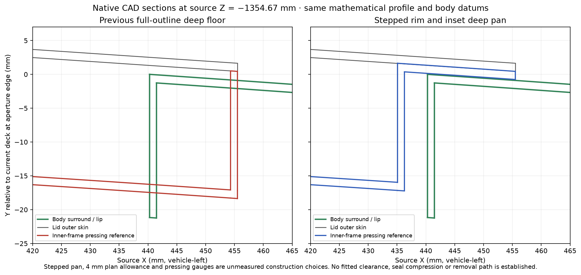
The deep pan uses an explicit unmeasured 4 mm plan allowance inside the reference aperture. Shallow-rim depths of 1.2–2.4 mm and the retained 20 mm central-floor depth are construction choices, not fitted dimensions or clearances. The same three access openings and all hardware stations stay. Shared body-derived sampling replaces the lid’s earlier coarse 33-station loft while retaining its mathematical profile, outline and pose. The old sampling alone could put the shallow rim about 0.45 mm below the independently sampled body surface.
Native frame/surround overlap falls from 7,556.67 to 10.79 mm³. The remainder is localized to the two forward hinge-boss references, about 5.39 mm³ each at the aperture’s forward edge. The broad deep-floor conflict is removed; fitted boss map, aperture layers and closure remain unresolved. Hinge-arm, striker, support and fixing/body contacts also remain recorded. The body was not cut or moved to erase them.
Skin/frame sampling and the pressing construction changed; the other 17 component meshes remain byte-identical, with their native volumes and bounds held. Those checks establish a more coherent reference, not loaded seal seating, supported opening, safe release order, actual clearance or a verified removal/refit path. Inner pressing, hem, welding and hidden joint dimensions remain unknown.
Native lid structure and closure joints
The closed lid now has a thin native skin and formed inner frame with three large access openings, following the architecture drawn in the factory parts plate. Separate gooseneck arms, flat leaves, body ears/pins and fixing sets replace the old above-skin hinge blocks. The locking handle, barrel/tail, latch case/tongue and body striker are individually selectable, along with four buffers and a parked later-support comparison.
Factory p.250 supplies the hinge pair/ten screws, handle/two nuts, separate latch and striker with two fixings each, two front/two rear buffers and the later AHA9716 support branch. The three lid-side/two body-side hinge screws per side are an unverified split/map of that total. British Motor Heritage’s catalog lists CZJ351 lid and handed hinge applications; it does not identify the fitted pressing or hidden joint dimensions. Badges and luggage-carrier options remain unselected.
Geometry basis and limits
The closed width and rounded outline remain estimates; height follows the same conditional rear profile through shared body-derived stations; the earlier 33-station approximation is superseded. The 1.2 mm skin is a projected vertical display section, not measured normal gauge. The central deep floor retains its 20 mm reference depth, while the stepped perimeter now uses shallow rim depths. These remain unmeasured pressing sections. Access outlines, edge returns, flat-leaf and latch-mount boss bridges, gooseneck sections and all mounting maps are estimates. The flat latch land and 0.5 mm handle-boss display gaps are construction choices, not fitted pressing or seat geometry. Pin centers move below the old above-skin cues to a deck-minus-28 mm comparison plane. No fitted hinge sweep or body-deck holes are invented.
Handle/skin/frame and latch/frame passages share estimated vertical drawing axes, not surveyed surface normals. The unphased square tail and static tongue/striker comparison do not reconstruct lock actuation, catches, springs or a verified locked state. Buffers and existing aperture seal remain unloaded; their source relationship does not prove closed fit or sealing.
Selected internal source comparisons: handle housing/skin 9.1327 mm³; inner frame/latch flange 0.0 mm³; latch case/static tongue 359.3281 mm³. Positive values are unresolved reconstruction contacts, not fitted interference or locked engagement.
Parked support and surrounding obstacles
The later support is represented by nested channel envelopes, bored end eyes and separate body/lid anchors. Its left-side placement and mounting map are construction choices, not fitted AHA9716 identification. Earlier rod/clip hardware is not transferred to this branch. The span remains in its closed reference pose when the lid anchor translates away in the inspection display; no extension, locking, gas assistance, capacity or safe supported-open state is simulated.
The original retainer contact is documented historically above; the current fixed-shroud reference has no positive contact with the native lid source. Deck surround/lip and aperture seal follow the revised profile; floor, tank, folded hood and rear-frame sources remain unchanged. Zero contact in a limited sample does not prove common registration, operating clearance, lid alignment or access to a hidden fastener.
The lid skin, inner frame and carried hinge/lock/buffer parts translate together. Body hinge plates, striker and parked-support body references stay fixed. This is not a release order, support plan, opening trajectory or verified replacement/removal path. Complete applicable workshop instructions, fitted attachments, loaded sealing and surrounding body registration remain unresolved.