Add the surrounding obstacles.
The tank, filler, sender, rear vapor separator and exhaust now occupy the whole-car reference beside the axle and spring connections. They add context for planning access around those assemblies.
The supplied side photos do not calibrate these hidden assemblies. Every new size, port, route, mounting position and chamber envelope is estimated. Apparent gaps and intersections are model results, not measured hot clearances or proof of fit. Separation directions do not verify a replacement procedure.
Fuel-storage relationships
The new boot-compartment study ↗ adds the floor, rear panel and lid above these existing tank references. Filler openings are estimates; no sender service hatch or verified tank/floor clearance is introduced.
| Reference assembly | What is represented | What remains unresolved |
|---|---|---|
| Rear tank | Hollow catalog-sized shell, flange, six stud/retainer roles and separate unloaded seating strips beneath the estimated floor. | Fitted identity, capacity, internal construction, mounting pattern and body registration. Manufacturer dimensions describe a comparison tank. |
| Filler neck and hose | Flexible tank-side connector and neck toward the rear body filler area. | Which factory hose/neck/cap variant is fitted, its bore and seal, routing, clamps and body opening. |
| Sender and ring | Separate plain sender head, unassigned terminal envelopes, locking ring and uncompressed seal. The old outlet-like cue is removed. | Float/pickup internals, wiring, seal dimensions, fitted sender and actual service access. |
| ELC separator comparison | Rear vessel, estimated tank-side hose and short outlet cue. | Fitted vessel, brackets and port assignment. The forward route now has an estimated reference with an explicit open front boundary. This is not a complete fuel/emissions circuit. |
The factory evaporative-loss-control plate, PDF p. 90 separates the tank, locking sender, filler variants and rear vapor separator. It lists BHH1626 separator from GAN6-154101 and CHA378 tank-side pipe through GAN6-182000. These are configuration references, not fitted identifications. Moss PDF p. 45, printed p. 27 also distinguishes filler variants and earlier rubber tank-mount items. The later native comparison includes six body-stud roles and two long/two short seating-strip roles from the supplier mounting description. These remain configuration comparisons, with no fitted identity or loaded compression established.
Hollow exhaust and cross-car relationship
The ordinary front downpipe comparison now feeds a separate native main-pipe reference across to the left longitudinal resonator. A short connection feeds the left end of the transverse rear chamber; a right tail replaces the old redundant cross-car return. This follows the factory plate’s chamber and LH/RH support interpretation, not a survey of this car.
Factory PDF p. 127 distinguishes the ordinary GEX1618 pipe from the California CHA287 catalyst assembly. P. 128 separates intermediate, LH rear and RH rear supports and the GAN6-169792 RH mounting change. MGOC’s own Double S replacement-system note describes the twin rear silencers and pipe contour accounting for the opposite-side 1500 manifold. It is a replacement-system comparison, not fitted identity or factory dimensions.
The old front/underfloor drawing endpoints differed laterally by 514.07 mm. The old endpoint is removed. The revised main pipe starts at the coupling rear face and bends across the car. The downstream front bend/coupling center lowers from Y=.23 to .12 body units (93.13 mm) to sit below the estimated gearbox; inlet flange and engine/body placement remain fixed. New path corner stations, tangent radii, 3 mm pipe walls, chamber walls, ports, mount patterns and support locations are estimates. Empty hollow chambers do not reproduce baffles or verified gas flow. Rear tank/body/exhaust registration remains provisional.
Intermediate, left-rear and right-rear clip/isolator references separate from fixed body-support bracket comparisons. The generic right-rear mount does not choose the early rubber-bush/spacer or later mounting branch. Contacts, support loads, rubber compression, threads and actual anchor identity remain unverified. General separation moves the exhaust groups down together; fixed body brackets are an inspection convention, not an attachment/removal instruction.
The factory configurations remain separate from the owner car: IMG_7042 shows only the manifold-area neck, and IMG_6329/6341 do not calibrate the hidden route or rear hardware. No fitted catalyst choice, hot clearance, ground clearance, gas sealing, support load, service sequence or verified extraction path is established.
Inspect the new feed and ELC connection study ↗ for the estimated forward pipes, separate carbon-canister boundary and observed electric-pump difference.
Rear registration remains open: the earlier 4.23 mm tank/exhaust drawing comparison is superseded by the catalog-envelope tank reconstruction. It must not be used as a current clearance. The mounting-layer review below compares the current source shapes without moving neighboring components to force a fit.
Tank, floor and rear spring mounting layers
The tank comparison now uses Spectra Premium RO9F catalog bounds: 723.9 mm width, 368.3 mm length, 203.2 mm height and 0.7366 mm sheet thickness. Those are manufacturer specifications for a comparison part. Interpreting them as flange-inclusive plan bounds and neck-inclusive height is an assumption. The actual car's tank identity, port map and mounting dimensions remain unknown.
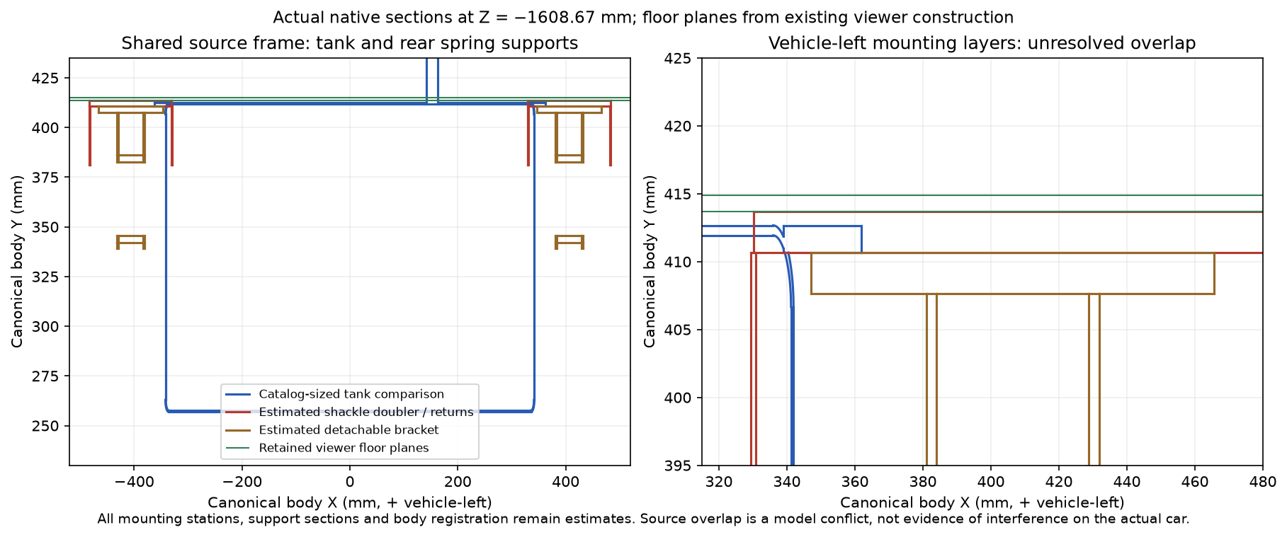
The factory luggage-floor plate, PDF 233 distinguishes the GAN6 CZJ569 floor assembly and CZJ644/645 rear bumper mounting beams. The model keeps the floor, bumper beams, suspension supports and detachable tank as separate assemblies. The drawing establishes architecture; it supplies no dimensional registration for this car.
| Relationship | Current model | Workshop implication |
|---|---|---|
| Floor / tank flange / seating strips | The flange lies 1 mm below the estimated floor underside. Separate 1 mm unloaded strips span that construction gap. | Loaded support, actual strip thickness, stud attachment and fitted floor profile are unverified. |
| Tank / rear shackle floor doublers | Approximately 7,982 mm³ source overlap per side, with additional support contacts recorded in the review. | These independent reference assemblies have not been reconciled. This is a model conflict, not evidence that the actual car has interfering parts. |
| Tank / exhaust | Current native intersections are recorded in the downloadable review. Zero intersection covers only those selected rigid shapes. | No hot clearance, suspension travel or tank extraction corridor has been established. |
The joined native floor and side extensions now retain the previous floor datums. Their initial native comparison recorded floor/tank overlap of 5,687.44 mm³ and floor/sender overlap of 4,618.14 mm³. The subsequent recessed sender-well reconstruction leaves 138.13 mm³ at the inherited vapor neck and no positive sender/floor intersection. Floor and tank mounting datums stay fixed. No sender access hatch or fitted clearance is inferred; see the current contact report.
Before this model can rehearse tank replacement, the tank flange and mounting map, rear shackle reinforcement extent, floor layers, filler connection and exhaust relationship need a common evidence-based register. The current separation remains an inspection aid. No source overlap authorizes cutting a panel, changing a catalog dimension or selecting a removal direction.
Use the obstacles when preparing a job
Compare the tank and exhaust with the rear spring eyes, shackles, clamps and dampers. Trace which hoses, wiring and supports would need attention using the applicable complete workshop procedure and the fitted car. This reference supplies no fuel handling, draining, disconnection, lifting, support or loosening sequence. It also supplies no validated extraction direction, suspension travel, heat shield layout or tightening values.
IMG_6329 and IMG_6341 retain their role as owner body/wheel context. Hidden underside and boot connections are not measured by those views, and engine measurements do not register the new obstacles. Geometry can therefore help identify neighboring assemblies while fitted identities and service access remain open evidence questions.
Rebuild the exhaust hanger chain
The intermediate, left-rear and right-rear support references now have split sheet clips, thin hanging links, separate plain fixing envelopes, annular unloaded insulators and formed body brackets with bored ledges. These replace the former thick rings, solid stems, cubic rubber blocks and solid body-anchor blocks. The five pipe/chamber meshes, front coupling and their installed reference stations stay unchanged.
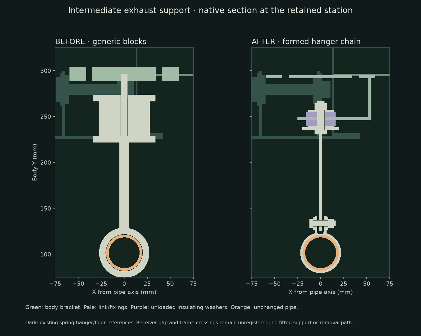
Factory p127 establishes intermediate clip, insulating-washer, plain-washer, mounting-bracket and fixing roles. P128 distinguishes rear supports and RH configuration branches. The RH annular pair shown here is a generic insulation-role comparison: it does not select the early GEX7151/GEX7166 bush/spacer arrangement or the later GEX7468/GEX7251 clip/rubber arrangement as fitted.
All profiles, gauges, bores, washer sizes, bolt lengths, positions and receiver maps are estimates. Insulators have no compression, stiffness or bonded ownership. Metal and rubber remain separate selectable references. The intermediate upper flange follows the existing floor underside only at its outboard edge; its inboard projected receiver falls in the existing spring-hanger floor pocket. The bracket also intersects spring-hanger source pieces. Rear body receivers remain unregistered. These are documented source discrepancies, not actual-car collision or support findings.
The unchanged main pipe still intersects the estimated gearbox crossmember and cradle by about 5613.56 and 4482.59 mm³ respectively. A connected route does not establish fitted clearance, so those frame discrepancies remain open. The new hanger geometry does not certify a pipe reroute, hot clearance, support strength or a replacement procedure.
The body brackets stay fixed during illustrative separation; hangers and insulating references share the exhaust display offset. That grouping is not a release sequence. Fitted mounting identity, body receivers, support arrangements, fastener access and surrounding obstacles must be established before a physical replacement rehearsal can be trusted.