Give the shackle
a separate body mounting.
The rear mounting now has a detachable three-screw bracket, paired cheeks and an open transverse sleeve, four flanged bush halves per side, a plate with two pins, a separate closing plate and retainer envelopes. Thin wheelhouses and formed reinforcement references add surrounding body geometry.
What the evidence changes
Factory rear spring fixings, PDF p. 150, distinguishes AHA7201 rear mounting with three body screws per bracket, AHA7686 plate with pins, AHA7687 closing plate and eight AHA7182 bush halves per car. The supplier’s own AHA7201 photograph shows paired triangular cheeks and a transverse sleeve. These sources correct the old solid mounting block; they do not identify the hardware currently fitted.
British Motor Heritage’s rear body drawing and applications separately list BMH8014/15 inner wheelhouses and AHA7240/41 wheelhouse-to-floor reinforcements. CZJ568 boot/cockpit floor and CZJ602 rear underframe are the rubber-bumper comparisons. Earlier complete body assemblies and round-arch alternatives are not imposed on this car.
Keep the body, bracket and joint distinct
The local doubler and open side returns stay with the body. The bracket is separate and can move illustratively. Its three bores share centers with the doubler and low boot-floor panel. This six-hole map is construction geometry, without a surveyed hole pattern, captive-nut arrangement or cutting template.
| Reference relationship | Basis and limit |
|---|---|
| Upper / lower eye axes | Retained at X magnitude .48, upper Y .43/Z -1.90, lower Y .33/Z -1.86 body units. These were drawing choices, not loaded owner measurements. |
| Bracket / body stack | Estimated 3 mm bracket and 3 mm local doubler meet the existing 1.2 mm boot-floor skin reference. Every fold, bore and attachment remains unverified. |
| Bushes and plates | Four separate flanged halves per side. Estimated 10 mm pin shoulders, 10.2 mm bush bores, 10.6 mm closing-plate bores, 4 mm plates and 3 mm bush flanges. Spacing changes to this declared stack; compression and fitted dimensions are unknown. |
| Thread comparison | Supplier GHF202 3/8 UNF nut listing is a nominal terminal comparison only. It does not prove pin shoulder diameter, actual thread engagement or fitted identity. |
| Inner wheelhouse | Retains .37-unit radius and .47/.74 X boundaries. The former membranes become estimated 1.5 mm solid sections, with explicit static reliefs. |
The previous 20.32 mm pin envelopes are replaced by estimated 10 mm shoulders. Front spring bushes, leaf/eye profiles, axle, damper and strap stations remain at their existing reference coordinates. Retainer rings omit actual thread and locking action; the displayed plate side assignment is not a verified fitted orientation.
Surrounding obstacles and open boundaries
The inner wheelhouse has a declared 34 mm-radius lower relief around the existing 32 mm-radius axle tube. A separate relief follows the retained damper body box plus 2 mm total across each dimension. Neither is a discovered factory opening, a fitted clearance or a suspension-travel envelope. Reinforcement sections follow the retained arch without a verified seam or continuous load path into the rest of the rear frame.
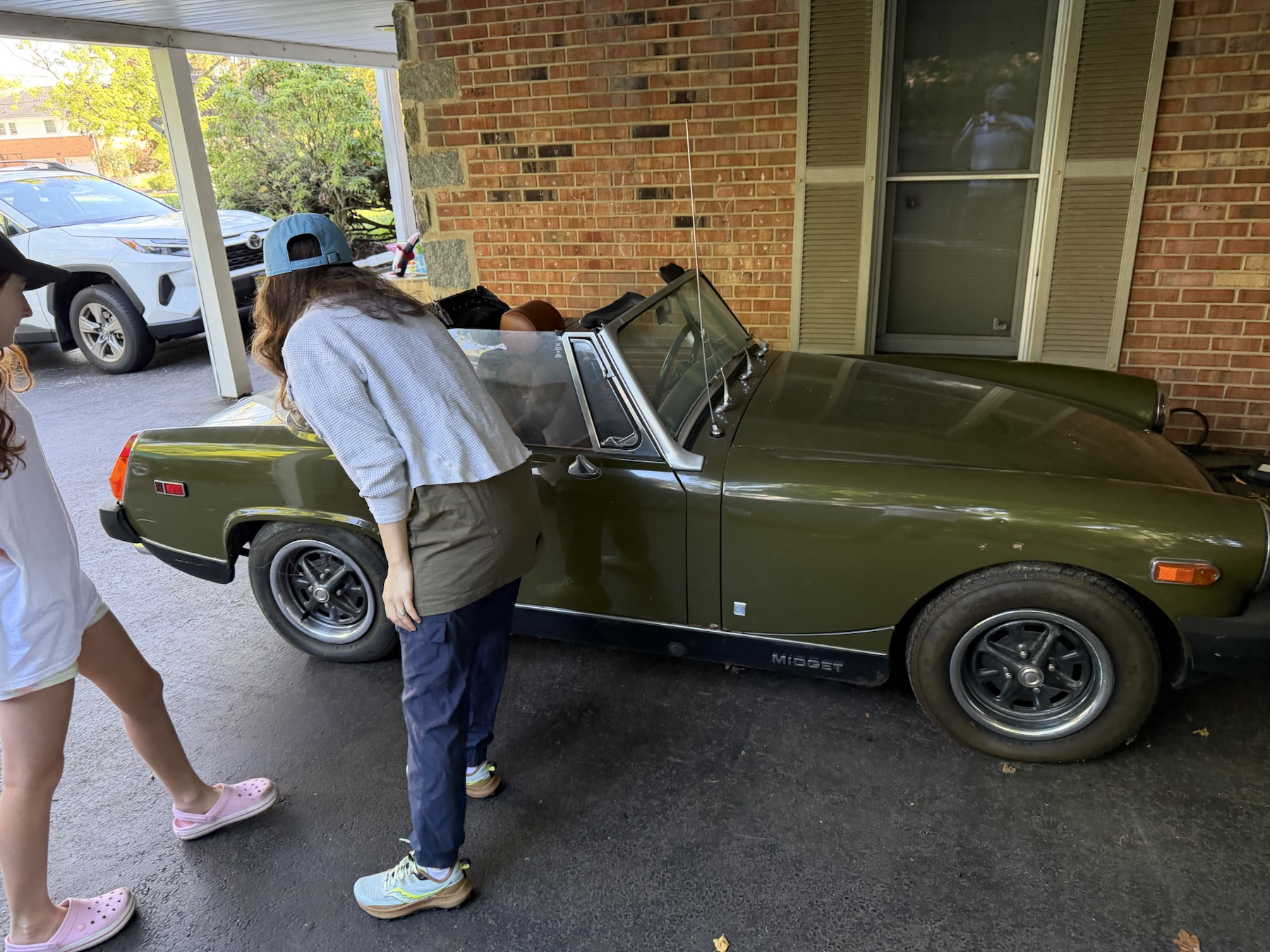
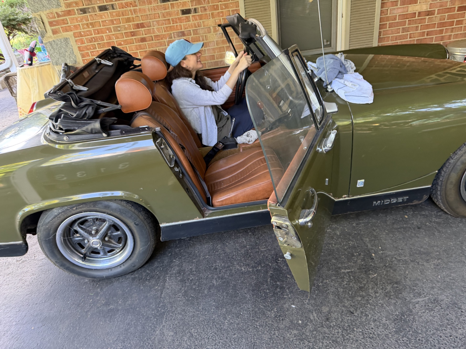
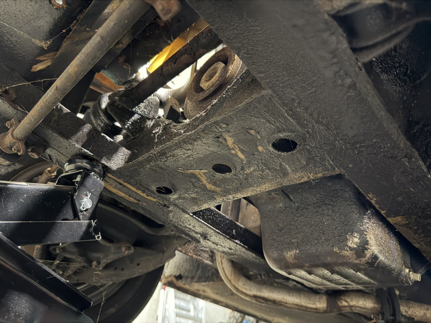
Owner IMG_6329 and IMG_6341 establish side/cabin context but hide the rear brackets and inner sections. IMG_6919 shows front underside context and cannot supply a rear mounting survey. No direct owner dimension is applied and no repeat capture is requested.
Separate formed damper/upper-strap panels, fixing envelopes and bumper beams now replace the old pads and pins. The factory lists AHH9158 bump rubber, but the current evidence does not locate its fitted attachment and strike surface. It is not placed by guesswork. Continuous rear-frame geometry, actual reinforcement seams and fitted upper-strap/damper retention still need reconciliation. Two narrow rear-open construction reliefs in the local floor doublers now accommodate retained low bumper-stud axes; these are not factory openings or a repair template.
Use the study for inspection rehearsal
Inspect the body/doubler, detachable bracket, upper bush pair, pin plate, closing plate and lower spring eye as separate interfaces. Keep the wheelhouse and body references visible to consider obstacles. The bracket, bushes, plates, bolts and retainers separate for visibility, without demonstrating a safe release sequence or extraction route.
Source checks establish valid solids, open shared body/eye passages and correspondence with the static axle reference. They do not establish body strength, load support, spring restraint, joint tightening, rubber compression, suspension articulation, brake-hose/cable/exhaust travel or a verified repair procedure.
Native exports
Eighteen source groups include thin wheelhouses, arch reinforcements, local doublers, brackets, body fixings, bush halves, pin and closing plates, and retainers. Other native assets remain unchanged. Browser checks cover shared bores and pin occupancy, body-frame placement, selection, isolation and inspection ownership.
Give the rear wheelhouses a dished wall and broad lower scallop
The manufacturer listing distinguishes BMH8014/15 inner assemblies, outer arches and separate floor reinforcements. The supplier’s own BMH8015 photograph shows a dished wall and broad lower scallop. The former flat walls and small round axle cuts now become connected wall-and-roof reference shells.
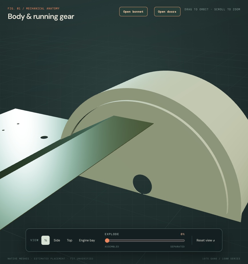
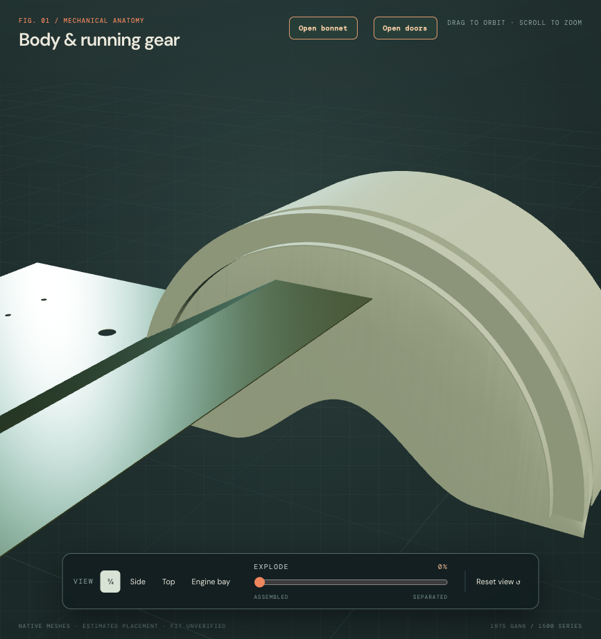
The old outer radius, transverse envelope and lower end plane stay. Dish depth 18 mm, scallop half-span 58% of the retained radius, rise 32% of that radius and 1.5 mm projected wall gauge are construction estimates. The product photograph is not calibrated, and left/right mirroring is unverified. No photographed boss or bracket is assigned an identity or copied into the car.
The broad lower opening follows supplier topology. It is not chosen from axle-contact calculations. The inherited damper-box relief remains an explicit unverified construction cut. Floor, reinforcement, shackle, damper, axle, spring and quarter sources stay; no panel is moved to conceal a conflict. The formed floor-reinforcement revision below now supersedes the separate semicircular strip.
At the wheelhouse-shell stage, the source had 18 groups and 62 positive valid STEP solids; the reinforcement revision below supersedes that solid count. Both revised shells are single connected solids; 16 other mesh records and native volumes stay. The unchanged boot floor has no positive shell overlap and approximately 2.27 mm nearest separation on each side. That unresolved source gap does not establish a fitted seam or clearance. Floor intersection measurements describe reference geometry, not welds, panel ownership, load paths or repair suitability.
No fitted body dimensions, actual lower pressing profile, suspension travel, wheel clearance, bump-stop mounting, body support, cutting/welding sequence or verified replacement/removal path is established. These welded references remain fixed during illustrative separation.
Follow the floor with formed reinforcement members
The factory body drawing, PDF p. 233 / printed 107-I10, distinguishes the AHA7240/41 reinforcements from the floor and wheelhouses. The manufacturer application listing and supplier’s own AHA7241 photograph support a long formed member with flanges and contour changes. The former semicircular strips around the arch crown now become connected floor-contour reference members.
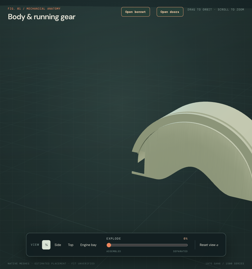
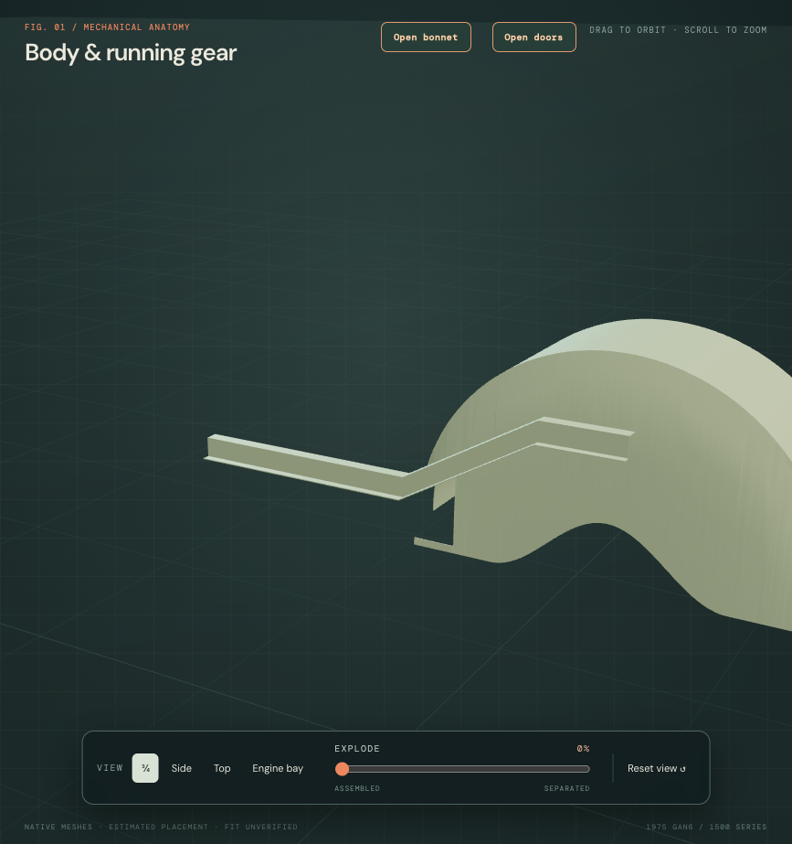
The existing unmeasured floor underside supplies the low, ramp and raised reference stations. A selected Z section has a 33.87 mm projected web depth, 21.17 mm outboard upper flange, 12.7 mm inboard lower flange and 1.5 mm projected gauge. Those are construction estimates, not recovered supplier dimensions or a developed pressing. The photo does not establish installed orientation, end curls, holes or receiver brackets; those details remain unassigned.
The upper flange shares the declared floor underside without positive material overlap. That construction contact does not establish actual panel ownership, weld/lap geometry, attachment strength or a fitted load path. The old arbitrary damper notch is not copied into the new member. Independent wheelhouse, floor, shackle, rear support and suspension sources stay in place; any source contacts remain documented rather than concealed with cuts.
The source has 18 groups and 58 positive valid STEP solids. Both new reinforcements are single connected solids; 16 other mesh records and native volumes, including both wheelhouse shells, stay. Each member remains about 2.17 mm from the wheelhouse source. The initial reinforcement stage recorded approximately 303 mm³ contact per side with the independent rear-frame reference and 2,903 mm³ with the damper/link source. The later formed-floor transition supersedes that section and changes the latter source contact to approximately 3,414 mm³. These unresolved reconstruction relationships do not establish actual-car interference or a fitted lap. The axle source has no positive member overlap; loaded suspension clearance is unverified. No body repair plan, support point, suspension travel, tool access or verified replacement/removal path is supplied.