Connect the spring, axle and body.
Each rear spring now has a fixed front-eye connection, a swinging rear shackle, an axle clamp stack, a damper link and a separate rebound strap. Body-side anchor references stay in place when other assemblies separate. This display convention includes service-removable brackets.
The factory plates identify the connections. The modeled installed spring shape, eye positions, bracket profiles, shackle angle, damper direction and strap slack are estimates. No fitted load, alignment, suspension travel, release sequence or replacement path is verified. The explode slider illustrates separation only.
Trace the two body connections
Front spring eye
The spring eye contains a bush and a transverse bolt through the front mounting bracket. Separate native front body pocket, lower plate, fixings and eye retainers now explain this interface. Inspect the front mounting correction ↗ All fitted dimensions, access and support remain unresolved.
Rear spring eye
A native three-screw bracket, sleeve, four bush halves, plate with two pins, separate closing plate and retainers connect the rear eye to the body. Inspect the rear body interface ↗ Joint axes remain drawing references; no fitted travel, loaded pose or tightening angle is established.
Follow the axle clamp stack
The native clamp source replaces the solid plates and oversized U-bolt sketches. Each side now has a separate curved upper cap, two smooth clips, separate upper/lower locating webs, an open locating collar, two narrower seating pads, a handed lower bracket with a transverse link eye, four separate bored nut/washer envelopes and an independent stud-ended damper-link comparison. The invented separate lower pin is removed. The original axle, spring and damper-link Y/Z axes are retained; the independent damper source revises axial arm/link offsets.
The factory fixing plate supports the component roles. Rimmer lists AHA8097 as 3/8 UNF; this gives the 9.525 mm nominal comparison shank, not fitted identification. The Moss hardware table identifies GHF223 as 3/8 UNF, 9/16 AF. Threads, locking and preload are not modeled.
Loop centerline radius is now 38.7625 mm around the existing 32 mm-radius tube reference and estimated 1.5 mm upper cap. The 0.5 mm clip-to-cap allowance is a construction choice; the earlier 37.5125 mm loop omitted the cap. Moss rear-suspension item25 places the curved cap above the clips/axle region, and the AHA8372 product photo supports its half-shell and raised edges. It is distinct from the unresolved lower axle seat. The later factory-section revision below supersedes the early 54.8 mm-wide pad sketch with a supplier nominal-plan comparison. Shared 10.8 mm holes are drawing geometry, not a drilling template. Plate gauges, outlines, lips, collar, bracket shape and every position remain estimates.
The former gap below the axle now contains the separate estimated under-tube seat described below. Its fitted height and contact remain unresolved. The earlier 2.6333 mm plain-eye gap belongs to the withdrawn separate-pin sketch. A native lower stud now passes an estimated R7.1 bracket bore; shoulder/reference-plane coincidence does not establish a fitted axial stack, spacer or loaded bearing. The separate spring source now has a center passage and unthreaded fastener comparison; axle-seat/recess engagement remains unverified. Apparent contact or separation cannot establish loaded pad compression, axle alignment, support, tool access or a removal path.
Connect the leaf pack
The native spring source retains the reference eye axes and spring stations. The later factory-section revision below supersedes the old five-leaf construction. Its main leaf now joins both eye envelopes. Each leaf has an open center passage with surrounding material; a separate round-headed smooth bolt and bored nut illustrate the center-fastener role. Four split band comparisons retain the shorter leaves visually. They are not a working retention system.
Factory PDF149 supplies only the complete CHA493 assembly for GAN6. The earlier AHA7813 toe bolt and ACA5000 distance-piece entries are not assigned to this car. The CHA493Q replacement photograph corroborates center-fastener and four-clip topology, not this car's leaf/clip count, fitted hardware or installed orientation. All bores, gauges, fastener dimensions and clip positions remain estimates. The round head has a 0.1 mm drawing gap above the curved leaf; no fitted bearing land or preload is fabricated.
The six-leaf factory comparison below supersedes the earlier five-leaf sketch; the fitted pack remains unidentified. The model cannot establish spring rate, free/loaded camber, interleaf material, pad compression, center-head location in the axle seat, load capacity or safe release/removal motion.
Connect the damper arm and link
The factory plate and AAU1949 supplier photograph distinguish an upper cylindrical bush case, slender rod and lower cup with opposite stud ends. Native geometry replaces the old rod with two plain eyes and separate lower pin. A tapered bored arm now sits outside the case instead of passing through its center; the case and root sections are subsequently revised below.
The factory lists 17H9275 before AAU1949 at GAN6-157672. Neither branch is identified as fitted. FNZ507 and FNZ508 supply separate catalog 7/16 and 1/2 UNF nominal shanks (11.1125 and 12.7 mm), not fitted thread identification. Both studs are smooth; nuts and round unloaded washer boundaries do not simulate thread engagement, locking or compressed split washers.
The earlier link revision retained the coarse case/shaft envelopes. The case revision below now supersedes those body/root sections while retaining the joint axes and shaft axial bounds. The arm moves outward by an estimated 60.0333 mm from the body-center drawing plane, with a 1 mm case/arm allowance. Link end offsets, length/lean, wall thicknesses, bore sizes, cup/shoulder gap, nut dimensions and every installed station remain estimates. The lower bore changes R11 to R7.1 around the smaller catalog-stud comparison; this is not a drilling or repair dimension. Hollow upper case and lower cup expose separate roles without claiming hidden bearing or damping construction. No working articulation, fitted preload, alignment, tool access or removal sequence is verified.
Keep bump rubbers distinct from rebound straps
The factory rear-spring-fixings plate lists two bump rubbers separately from the two rebound straps. PDF p. 150 identifies AHH7074 as the earlier rubber, used before AHH9158; the AHH9158 change-point entry includes GAN5-77979 onward. This catalog family is a comparison, not identification of the parts currently on this 1975 car. BHH989 is the separate GAN6 rebound-strap reference.
AHH9158 bump rubber
The factory drawing and supplier photographs show a shaped rubber body with an axial opening. It belongs to the compression-stop architecture, separate from the damper link and rebound strap.
Unresolved: Fitted presence, identity, condition, mount, retention, orientation and body strike surface.
Supplier replacement envelope
Philips Classics lists 55 mm outside diameter, 55 mm overall height and 14 mm / 18.70 mm internal diameters. Its own opposite-end photographs show unequal openings.
Unresolved: The listing does not locate the internal steps or give their depth, profile or retaining geometry. These are replacement-product dimensions, not owner measurements, factory tolerances or a verified fit.
Existing model
The axle, spring clamp, damper link and rebound strap already have separate reference geometry.
Unresolved: Bump rubbers, their mounting/retention and a located body contact surface are absent. The model cannot establish compression travel, which part contacts first, or available brake-hose/exhaust clearance.
The rubber dimensions alone cannot locate its installed center or establish the opposing surface. The factory axle illustration on PDF p. 146 supplies casing/support context but does not dimension that interface. No axle, body, spring or strap reference has been moved to close this gap. There is no inferred rubber compression, load curve, stop clearance, droop limit or replacement sequence.
Factory spring fixings, PDF p. 150 ↗ · MGOC replacement photograph ↗ · Supplier dimensions and opposite-end photographs ↗ · Evidence and remaining attachment dependency ↗
Keep the rebound strap separate
The rear body-support study separates formed panels, mounting ears, fixing envelopes, upper strap pins and bumper floor beams. The damper link connects the arm to the spring-clamp bracket; the rebound strap independently connects body and axle. The strap's bowed profile does not establish free length, full droop or brake-hose allowance. Bump stops and their fitted attachment remain unmodeled, so neither end of suspension travel is validated.
Factory references and changes
| Factory plate | Reference configuration | What it does not identify |
|---|---|---|
| Rear springs · PDF p. 149 | CHA493 spring assembly from GAN6-154101. | This car’s fitted spring, leaf count, rate, free camber and loaded shape. |
| Spring fixings · PDF p. 150 | Four AHA8097 axle clips; four ACA5139 locating plates and four ACA5138 seating pads per car; AHA7172 RH / AHA7173 LH damper-link brackets; AHA7686/AHA7687 shackle plates. | Fitted threads, bore sizes, pad compression, clamp torque, alignment or fastener access. |
| Same fixing plate | BHH989 rebound straps from GAN6-154101, distinct from earlier AHH5081. | The installed strap identity, free length, strength or droop limit. |
| Rear dampers · PDF p. 151 | GSA149 RH / GSA150 LH. Link 17H9275 precedes AAU1949, with AAU1949 from GAN6-157672. | Which link is fitted to this car, its length, bush dimensions or operating angle. A generic “1500” listing does not resolve the change point. |
Moss PDF p. 64, printed p. 46 separately illustrates quarter- and half-elliptic systems. This model uses the half-elliptic architecture. The quarter-elliptic radius arm and the catalog’s earlier-car lowering or tube-damper options have not been treated as fitted equipment.
What the existing evidence supports
The supplied side view IMG_6329 supports body and wheel context. It does not expose the rear eye, shackle, pads or damper markings, and it is not a calibrated ride-height survey. The existing engine measurements use a separate frame. This pass can therefore add substantial factory-based reference geometry without claiming that hidden rear hardware has been measured.
The old round-tube spring sketch is replaced by flat graduated leaves, with the center below the eyes. Spring pitch is moved inside the existing axle-tube span. The earlier five-leaf drawing and the shallow curve are explicitly illustrative; they are not a fitted count or a validated free or loaded spring shape.
Use the model to prepare a job
Inspect the spring, its two body connections, clamp stack and link before assigning parts to a replacement plan. Keep the fixed body references visible when considering surrounding obstacles. Physical removal still requires the applicable complete workshop procedure, body and axle support, control of spring load, fastener specifications and final checks. No loosening order, support point or extraction direction is supplied by this model.
Give the rear damper its paired barrels
The factory rear-damper plate, PDF p. 151 / printed 107-F14, and both handed supplier comparison photos show paired lower barrels and a lower crosspiece beneath a compact upper case. The old box and single lower cylinder now become a hollow case/barrel comparison, separate upper cover and separate estimated smooth output shaft on its retained axis. GSA149 RH and GSA150 LH are comparison roles; neither is identified as fitted.
Inspect left damper ↗ · Inspect right damper ↗ · Body mounting context ↗ · Evidence / dimensional classes ↗ · Native checks ↗
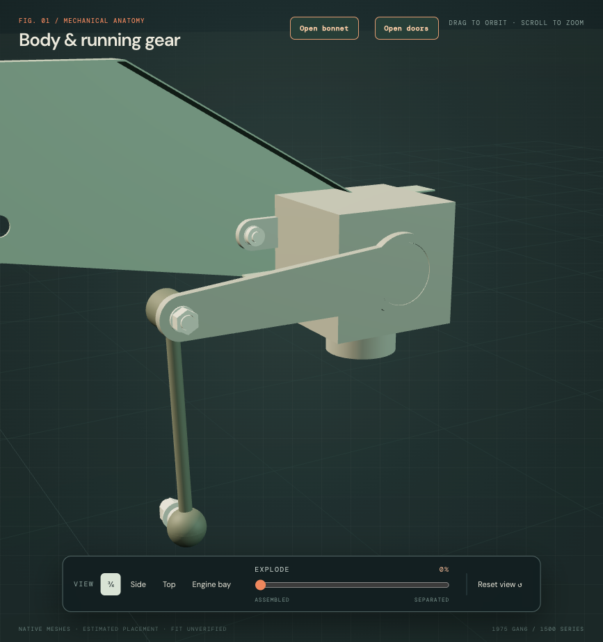
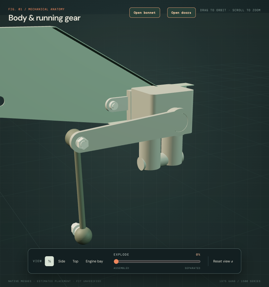
All casting dimensions, empty cavity sections, cover, back flange and shaft-bore allowance remain estimates. The shaft axis/axial bounds, arm/link joint centers and body mounting stations stay. Qualitative supplier-photo proportions under a chosen 100 mm case-face reference guide the new 18 mm shaft radius, 25 mm case boss, 27 mm arm-root radius and 24 mm root half-width; no scaled tracing or fitted diameter is recovered. The separate inherited mounting ears intersect the back flange as reference casting envelopes; this is not a verified loaded clamp or thread engagement. Existing mounting hardware is unchanged; factory washer roles do not certify that estimated stack.
The hollow case is not a hydraulic model: no piston, valve, oil path, seal, working bearing or damping behavior is established. The shaft and root sections remain unmeasured construction geometry. Existing link change-point alternatives remain unselected. No support/release sequence, torque, loaded travel or verified removal path follows from the parts illustration or display separation.
Support the axle above the spring stack
The factory axle drawing shows lower seat structure, while the spring-fixing plate separates the locating plates and pads. Two open under-tube seat comparisons now connect the retained tube surface to the upper locating-web reference. The separate upper curved cap is retained above the tube; it does not perform this lower-seat role.
Inspect left axle seat ↗ · Inspect right axle seat ↗ · Evidence and bump-stop gap ↗ · Native checks ↗
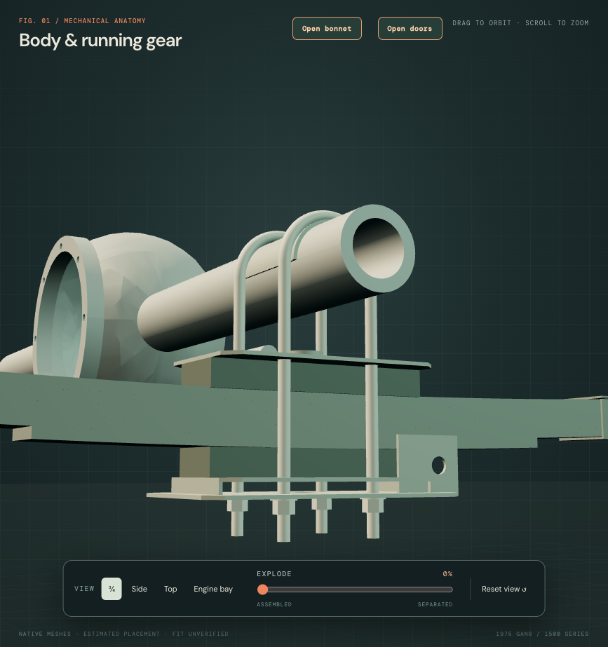
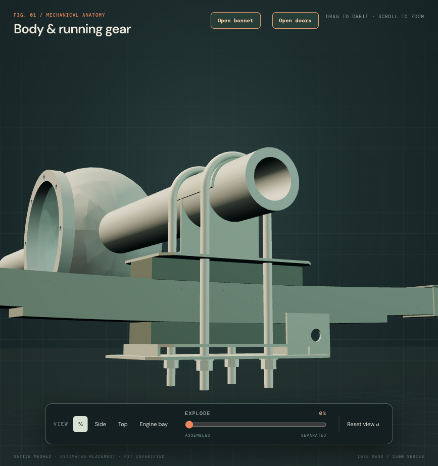
The 60 × 66 mm footprint, 3 mm sheet, 15.2 mm center opening and side-cheek sections are construction estimates. The bottom follows the retained upper locating-web top; the cheeks follow the R32 tube. No axle, spring, plate or fastener moves. Face coincidence connects a declared reference stack; it does not measure actual seat height, prove clamping or establish weld/strength. Inspection separation carries the seats with the axle.
Bump-stop placement remains unresolved
The factory lists two AHH9158 rubbers, and the supplier lists a 55 mm outside diameter and overall height. The 14 / 18.70 mm internal values lack section datums and are recorded without application. The lower retention form, fitted axis and body strike surface remain unknown. A stop centered above the current spring axis would intersect the estimated wheelhouse wall; no stop or strike plate is placed to conceal that conflict. No compression travel, loaded clearance, support point or replacement path is established.
Use the factory rear spring sections
The accessible factory general specification, PDF p. 13 / printed 04-3, gives six rear leaves, 37.85–38.50 mm wide and 4.24–4.50 mm thick. The former five-leaf drawing used 50.8 mm width and 8.47 mm projected thickness. The reference now uses six leaves with midpoint 38.175 mm width and approximately normal 4.37 mm sections. This is a factory configuration comparison, not a measurement or identification of the pack fitted to this car.
The existing eye centers and central main-leaf datum stay. Leaf lengths and shallow installed curvature remain estimates; the sixth half-length is chosen construction. Short terminal blends connect the narrower main leaf to gauge-matched eye rolls around the retained unmeasured bore and axes. The factory’s 141.7 mm free camber is recorded without application to the installed frame.
Inspect left six-leaf reference ↗ · Inspect right reference ↗ · Factory / supplier evidence ↗ · Geometry and source gaps ↗
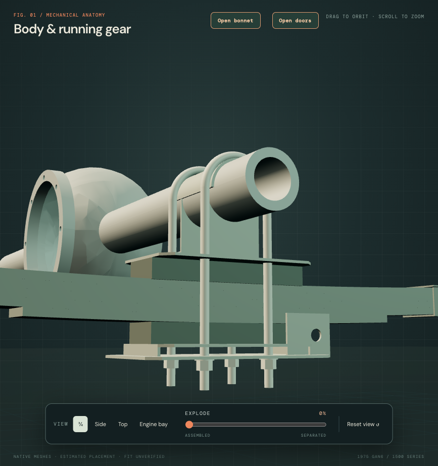
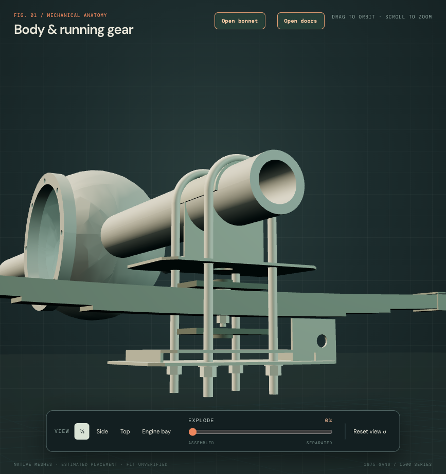
The ACA5138 supplier listing gives 87.6 × 44.6 mm and a 15.3 mm center hole. Its photo shows a thin body and raised neck. The 6 mm body, 4 mm neck, neck radius and orientation remain estimates. Existing pad leaf-side planes and steel/axle/perch stations are held. The new sections expose source gaps and an estimated center-head/pad-hole conflict; no counterbore or spacer is invented to conceal them. These are unresolved reference relationships, not proof of actual-car interference or loaded fit.
The separate center fastener and four bands remain unselected constructions. No spring rate, loaded camber, compression, strength, support/release sequence, torque or verified replacement path is established.
Use one locating plate above and below the spring
The factory spring-fixing drawing, PDF p. 150 / printed 107-F12, lists four ACA5139 locating plates. The MGOC listing and its ACA5139 photograph show a near-square four-ear outline, four corner holes, a central collar and opposing folded sides. The former long upper web and differently shaped lower channel now become opposite orientations of one reference profile.
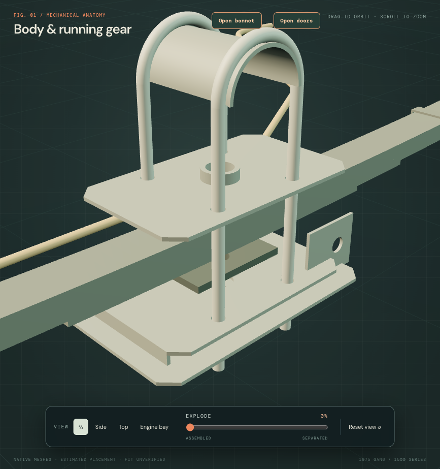
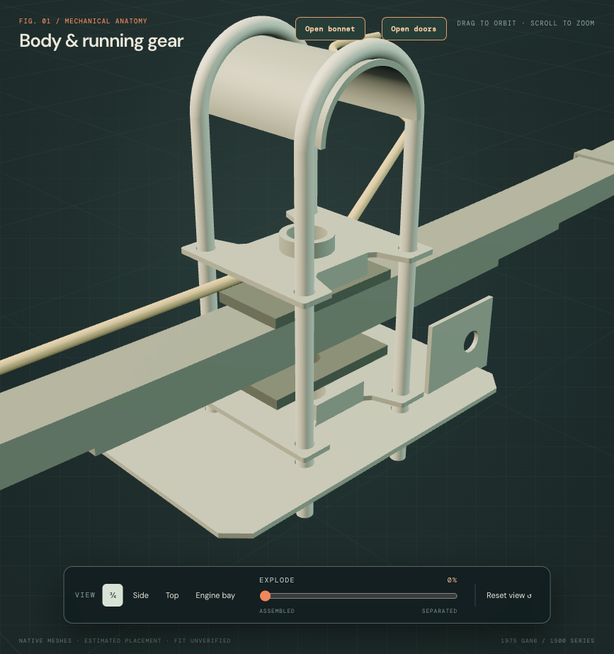
The 96.2 × 97.525 mm outline follows the retained unmeasured U-bolt axes plus a selected 10 mm margin. Web gauge, ears, fold direction, fold dimensions and collar are construction estimates, not supplier dimensions or a scaled tracing. The lower plate mirrors the upper profile. Existing hole axes, pad-facing web planes, pads, axle seats, spring, clips, bracket and feed pipe stay unchanged.
The old 74.7 mm³ pipe/web intersection is historical. With the revised plate, the unchanged source pipe has no positive plate overlap and a nearest upper-plate separation of approximately 1.21 mm. The pipe is not an input to the plate reconstruction. This result establishes neither actual-car clearance nor loaded suspension behavior.
All 34 STEP solids are positive and valid; 16 unchanged clamp mesh records and native volumes are preserved. Four plate profiles change. These checks do not establish fitted dimensions, pad compression, collar/head engagement, clamping strength, axle alignment, torque or an actual removal path. The parts drawing is not a workshop release procedure.