Within the door.
Across the jamb.
Each door now has a separate inner access frame and trim board, body/door hinge leaves, latch/striker, static regulator, glass carrier/guide/stop, inner controls and a North American impact-bar comparison. The complete door can now open around its estimated hinge line for inspection. Raised glass, regulator and lock mechanisms remain static.
Inspect the two doors
The trim envelope covers the inner access openings in the assembled reference; isolation and general separation expose the support/mechanism shapes. The crossed regulator arms and toothless sector are recognition geometry only. No compatible scissor geometry, tooth count, roller engagement or regulator travel is established. Latch and striker mouths do not verify locking or secure door closure.
Owner evidence and factory branches
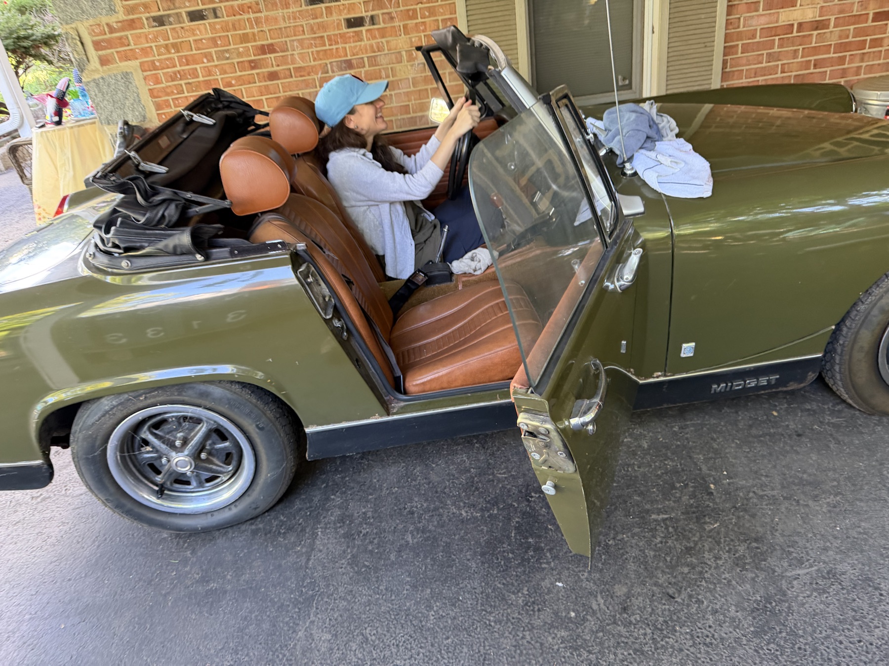
IMG_6341 shows the right door open with raised glazing and visible trim/handle context; IMG_6329 shows the closed exterior. These views do not survey hidden mechanisms, fasteners or attachment coordinates. The left side repeats the right-side context by an unverified symmetry assumption.
Factory PDF p. 239 separates USA/Canada door assemblies, hinges and inner-panel architecture. PDF p. 241 and p. 242 distinguish later latch/striker and lock/handle branches. The comparison does not identify the fitted locks or reconstruct the remote-control rod/linkage.
PDF p. 243 separates lower glazing carrier, rear channel, stop and AHA8533/34 regulator architecture. PDF p. 244 lists regulator mounting, winder and stop details. Catalog part numbers and stock strip lengths are not fitted dimensions or a fastener map.
Preserve the North American difference
British Motor Heritage’s door listing explicitly excludes the North American side-impact bar from its replacement door. A separate bar envelope keeps that configuration distinction visible. Presence, condition, section, attachment and strength on this actual car remain unverified; the envelope is not an approved reinforcement design or replacement selection.
A declared glazing alignment
The previous pane base sat slightly outboard of the waist skin. Its drawing base now shifts from X magnitude .740 to .714 body units, approximately 22.01 mm inboard, to align with an estimated waist slot and carrier. Its raised profile is retained. This is reference construction, not a survey of glass, seals, quarterlight, guide fit or operating clearance. The slot, carrier and rear-guide sections are estimates.
Door-side groups share the existing whole-door display translation; body hinge leaves and strikers stay fixed. The trim has an extra inspection offset. Open doors now rotates the complete door-side assembly around the retained estimated hinge axis. The 60-degree display pose does not establish a fitted stop, check-strap limit, collision clearance or extraction path. The glass stays raised and locks do not actuate. All added outlines, bores, mount patterns, linkage stations and trim details are estimates. Tool access, seal compression, loads, impact performance and verified removal procedures remain unresolved.
Separate CAD reference
Construction checks cover valid solids, STEP round-trip, inner access apertures, source scale and waist-slot alignment. They do not validate fitted mechanisms or clearances. Other native exports are unchanged.
Reconstruct the parallel-arm regulator
The former internal reference used crossed round rods and a disconnected circular drive cue. Factory plate243 and a donor photograph instead support parallel lifting arms, two mounting plates, a formed lower return and a top connecting link. Those major shapes now replace the crossed rods on both sides. Separate bored roller and axle references meet a new open-inboard C track below the retained glass-holder channel. The glass, rear guide, winder input, hinge axes and all surrounding body stations stay fixed.
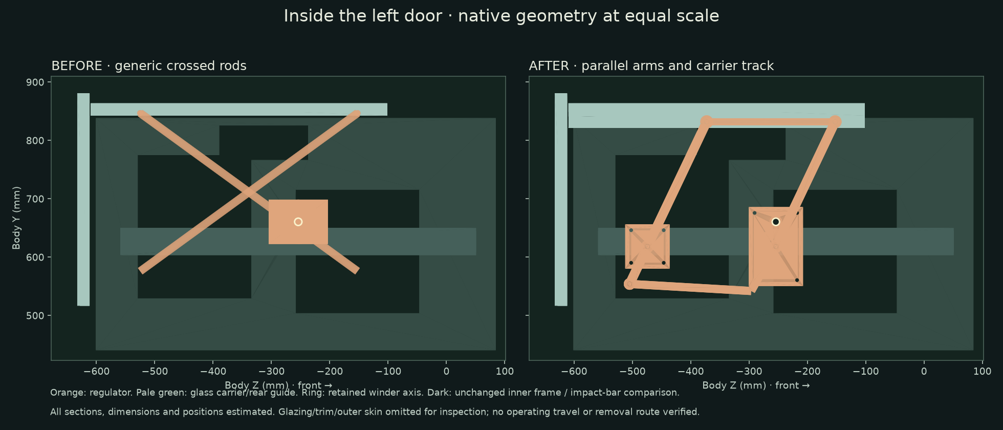
Factory plate243 lists AHA8533 RH/AHA8534 LH regulators through GAN6, with separate AHA7042 lower channel and AHA8405/06 rear-guide roles. The 37H4297 glazing-channel length is a separate lining comparison; it does not dimension the metal carrier. British Auto Salvage’s regulator photograph supplies unscaled external architecture. Its photographed hand, exact variant and presence on this car remain unverified.
All arm lengths, pivots, plate profiles, bores, gauges, roller dimensions, track section and raised pose are estimates. Smooth sector/pinion envelopes do not establish tooth engagement, ratio, return spring or operating selection. Mounting holes remain unassigned comparison features without a verified body receiver, drilling map or screw assignment. Existing impact-bar presence and all loaded/operating clearances remain unverified.
Native checks confirm valid positive solids, unchanged neighboring source meshes, joint/axle material and roller space in the carrier. They do not establish a working linkage, glass travel, support strength or tool access. The complete-door opening remains illustrative; regulator replacement still requires fitted mounting, glass support, channel/stop release, hardware access and an applicable procedure before a removal rehearsal can be trusted.
Connected hinges, complete door motion
The former disconnected flat leaves and tubes are replaced by connected curved-arm and fork-base references at each of the four retained hinge axes. The supplier AHA7428 photograph supports gooseneck/fork architecture; factory p239 distinguishes four hinges, eight HZS505/LWZ505 and twelve PMZ408/LWZ404 fixing roles. This is an architectural comparison, not identification or a dimensioned copy of the fitted hinges.
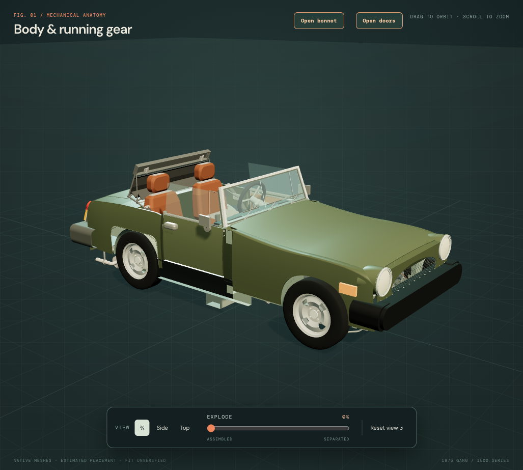
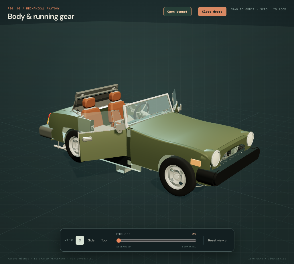
Owner IMG_6341 supplies the open-right-door and raised-glass context. The display angle is an explicit 60-degree construction choice, not a measurement from that photograph. Both sides use the existing mirrored reference assumption.
| Relationship | Current behavior | Still unverified |
|---|---|---|
| Carried door assembly | Skin, mirror/outer handle, main pane/quarterlight, inner access frame/trim, door-side hinge bases, latch, channels, regulator, stop, inner controls and impact-bar comparison share one rigid rotation per side. | Actual bar presence, component dimensions, seals, fitted alignment and operating loads. |
| Body-side references | Gooseneck arms and reference pins, strikers, posts, sills and inner-pillar receiver bores remain fixed. The existing two body receiver axes per hinge stay. | Actual tapped plates, mounting layers, pin retention, A-post relief and loaded support. |
| Hinge geometry | Each arm/base is one connected solid. The central eye and outer ears share the retained pin line; a three-hole base replaces the two-hole base approximation. | All curve/section sizes, drilling maps, gauge, running fits and handed installation. |
| Inspection and workshop | Open doors exposes the doorway relationship. The separation slider still separates trim and other groups illustratively; Reset view closes the doors. | Check strap/stop, full-car collision sweep, glass/lock actuation, safe support, fastener-release sequence and verified removal paths. |
Native checks compare hinge-only source intersections at 0, 15, 30, 45 and 60 degrees per side. They do not establish clearance to the surrounding car or validate a real opening limit. The body mounting is not changed to force a fit.
Connect the quarterlight to the door
The former quarterlight had only a glass plane and cylindrical perimeter. It now has a separate outer channel frame, inner U frame, inset pane, unloaded perimeter seal and glazing rubber. Its rear upright continues below the waist as the front guide for the main window; a short front foot supplies the other lower frame boundary. The main pane now has a finite display section and extends into the retained lower glass holder.
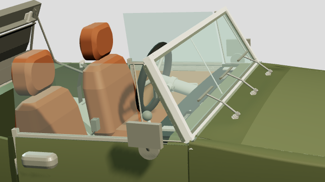
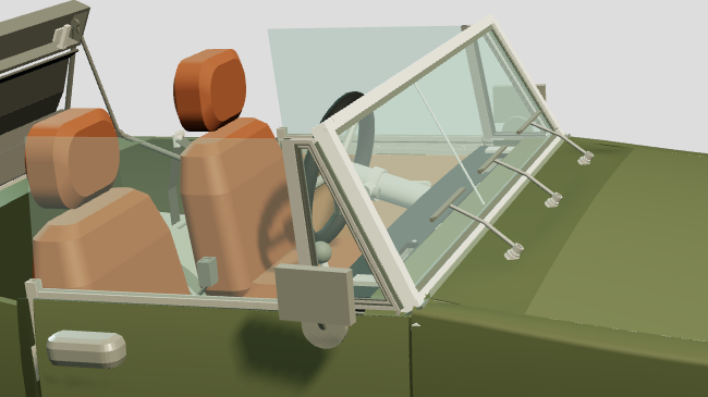
Owner IMG_6341 shows the raised glass and metal quarterlight surround on the open door. Factory plate 245 separates the outer frame, inner frame, glass, rubber and pivot roles; plate 246 adds the long door-glass channel, frame foot and door attachment roles. The later GAN6 catalog branch remains a comparison, not identification of this car’s fitted frames or finish. The supplier register distinguishes the glass, felt and seal roles; it supplies no fitted dimensions used here.
The existing visible quarterlight outline, main upper corners, door/screen frames, carrier, regulator and hinge axes stay fixed. The 4 mm lateral glass display depth, frame sections, inner offsets, guide length and short foot are construction estimates. Glass outlines are not cutting templates. No fitted fixing axes or body receivers are created; vent pivots, handles, drainage, seal compression and working window travel remain incomplete.
Below the waist, the long guide follows the retained carrier/rear-guide lateral plane; the upper glass lean is not extrapolated outside the door skin. This estimated transition does not define a working glass trajectory. The short front foot crosses the retained door hinge-leaf comparison by about 1,605 mm³ per side. Actual foot/hinge ownership, attachment offsets and the North American bar’s fitted presence remain unresolved. The source intersection is not a measured interference on the car.
For a replacement study, distinguish the main pane and holder from the quarterlight’s frame/guide assembly, its separate inner frame and rubber. Inspect these groups in the model alongside the retained door hardware. Every new piece follows the complete door in the illustrative opening view; that motion does not demonstrate quarterlight extraction, release order, supported glass, operating travel or a verified removal path.
Checks cover connected frame/guide geometry, the open guide section, retained raised upper corners, native/mesh volume agreement and twenty-two unchanged existing door meshes. Thirty-six source meshes load at native metric scale; the whole-car browser checks preserve the surrounding assembly positions and carry all twelve new/replaced inspection groups with the doors. Earlier door reports retain their historical scope and source counts.
Give the door hardware a native shell
The curved outer doors previously existed only as browser surfaces and end returns. Each native inner access plate stood separately inside. Both doors now have a native curved outer skin, estimated lower/end fold returns and outer waist ledge, plus a connected inner access frame with lower/front/rear perimeter webs and an inner waist lip. The existing exterior outline and body placement stay; this is a more complete enclosure, not a newly measured door profile.
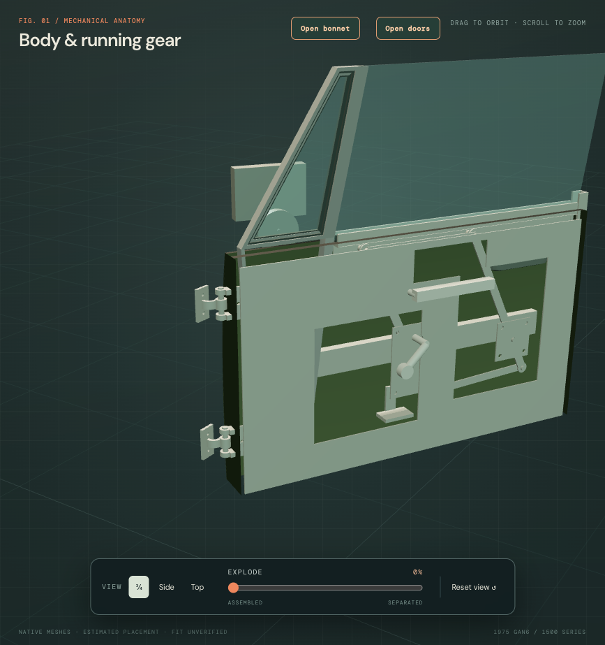
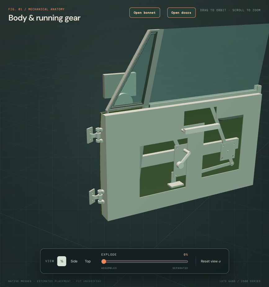
Owner IMG_6341 shows the open door, exposed waist and raised glass. British Motor Heritage distinguishes assembled BMH8000/8001 doors from CZJ707/708 outer skins, and explicitly excludes North American impact bars from its replacement assemblies. This establishes separate component roles, not this car’s installed identity or hidden sections. The existing bar comparison remains unselected.
The 1.2 mm projected outer section, 12 mm lower/end fold references, 1.5 mm perimeter webs and the inherited 2.54 mm projected inner plate are construction estimates. They are not measured gauges, crimped hem details, weld ownership or a repair template. The waist slot retains its estimated lateral bounds. No fitted hinge/latch receiver bores, drains, lock barrel or impact-bar anchors are fabricated.
Thirty-four previous door mesh groups remain byte-identical. Original access-plate material and apertures, regulator, glass, frame, channels, latch and hinge source coordinates stay. The browser mirror/handle fittings retain their world placement and move with the complete door. Two new outer-skin groups and two expanded inner-frame groups bring the source to 38 meshes and 92 valid native solids; these counts do not measure fidelity.
The retained rear guide/carrier group crosses the new outer/inner end boundaries by about 1,712/6,057 mm³ per side. The door-side hinge leaves meet the inner perimeter by about 860 mm³. Small quarterlight-foot contacts also remain. These are intersections of unregistered source geometry, not measured interference on the actual car; no hidden aperture is cut to conceal them. The outer/inner perimeter’s own roughly 2,209 mm³ overlap is declared construction joining, not a fitted hem or weld.
Use the shell, waist slot and access apertures to inspect the space occupied by the retained regulator and glass supports. Selected cavity and slot witnesses are open, but they do not establish complete moving-window clearance, fastener access, safe glass support, a release sequence or verified extraction. Door opening is still an illustrative rigid motion.
Validation covers native/mesh volume agreement, connected positive solids, retained exterior boundaries and original access material, selected open cavity/slot witnesses, unchanged surrounding source frames, retained outer fittings, picking and illustrative carriage. Historical door reports describe their earlier geometry and source counts.
A full pane inside the door
The raised main glass now continues below the waist into its setting rubber and lower carrier. The regulator arms and upper roller pins connect to that lower carrier while the mounting pivots and winder axis stay fixed. Both visible upper pane outlines stay unchanged.
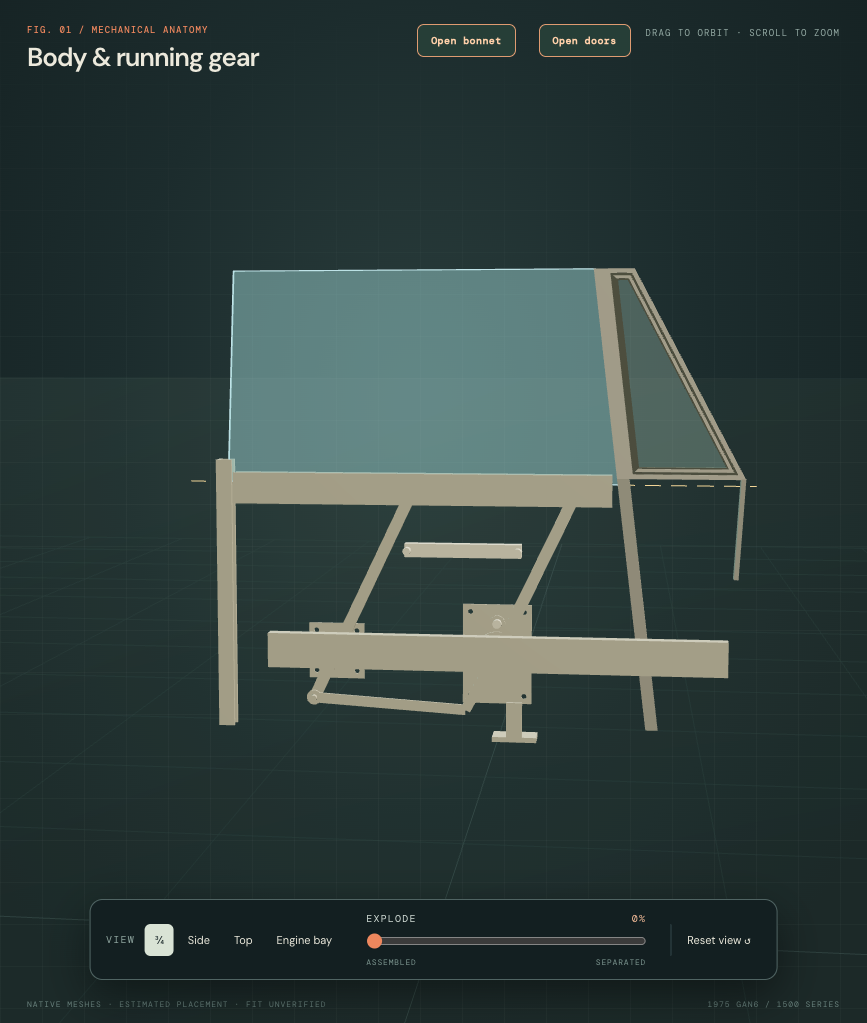
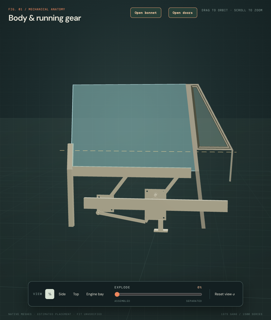
The 80 mm hidden extension is an estimate. Factory p243 establishes separate glass, setting strip, lower channel and regulator roles; it does not measure the fitted pane or arm lengths. Its 467 mm strip comparison does not establish the retained 508 mm carrier length. Ten of 38 groups change; 28 source meshes remain identical. The original door-hardware exports remain available as the earlier construction.
The lower guide knees, arm lengths, carrier depth, pin extension and mirrored geometry remain static construction assumptions. They do not establish compatible window travel, gear engagement, fitted clearance or a replacement path. Both sides retain their prior raised reference state: the photographs do not establish that the far pane is down. Windscreen curvature also remains unresolved; the screen is still a flat approximation.
Workshop use: this cutaway explains the glass–setting–carrier–regulator relationship. It is not a release sequence or extraction rehearsal.
Exterior mirrors: preserve the photographed asymmetry
The earlier browser model drew a circular foot, short tube and complete steel box head on both doors. The owner photographs support a different state: IMG_6329 and IMG_6341 show the near/right support or plinth with no complete head visible; a complete far/left head is visible in IMG_6341. This is a photographed state, not proof of permanent absence, damage or current condition.
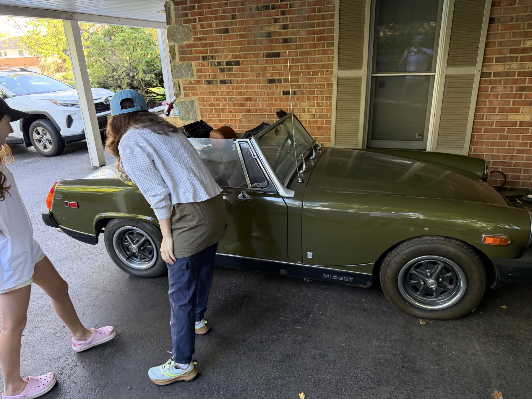
The new model has nine separate groups. It shows support envelopes, unloaded plinth seals and hidden mounting-role comparisons on both doors, plus a connected neck, open shell and opaque rearward-facing head on the left. It does not invent a right head. The left support’s hidden shape is a family comparison, not geometry recovered from the distant photograph. Original door handles and all thirty-eight earlier native door/glazing/hardware mesh records stay.
Factory PDF 275 distinguishes BHH1395/BHH1396 mirror roles with fixing plate CZK6342, plinth CZH3521 and mounting plate CHA176 through GAN6-175833; the HZA5074/HZA5075 and breakout-plate branch starts at 175834. The source’s plinth labels remain separate branch evidence. No chassis or fitted mirror identity is selected, and no replacement part is recommended.
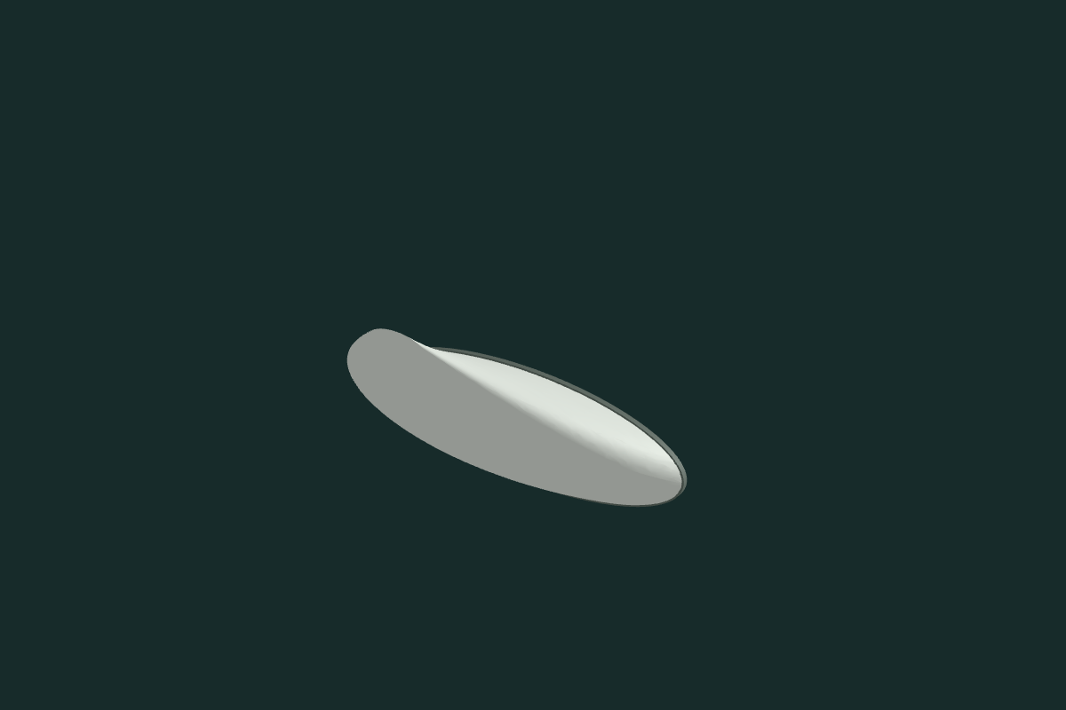
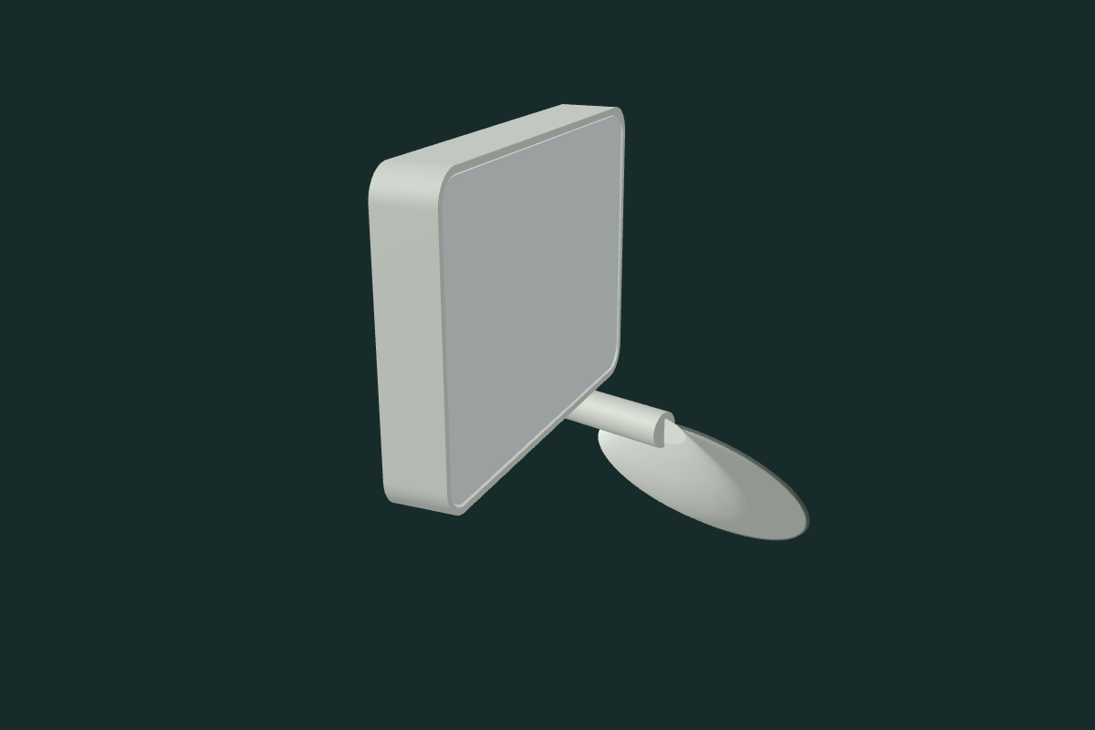
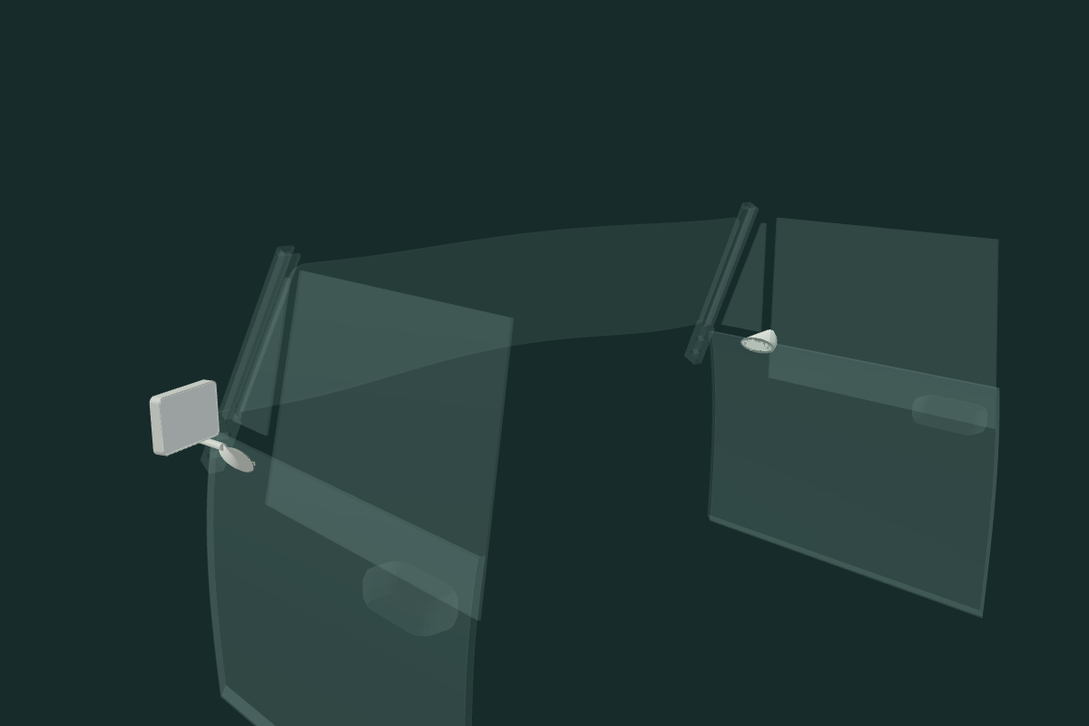
Support root outline 95 × 32 mm, crest, seals, hidden plates and fixing map are estimates. The left head is estimated at 125 × 88 × 18 mm with 25° yaw, using its old drawing center. The new root station follows the current door-side construction band rather than the old outboard circular pedestal; it is not an owner measurement or surveyed registration. No door, glass, frame or hinge is moved and no receiving holes are cut in the door. Positive contacts and gaps remain source conflicts. Door animation verifies a numerical inspection pose, not stop travel, loaded attachment, breakaway behavior, watertight sealing, collision clearance or a removal procedure.