Join the floor
to its tunnel.
Thin floors now meet the declared tunnel base and separate inner-sill webs. A hollow tunnel, an estimated rear flare, open rear-floor half-channels and a lower heelboard replace coarse surfaces and solid bars around the cabin and driveline.
Current cabin revision: the main model now uses lower intact upholstery, shorter estimated frame posts and a revised parked hood. Floor stations and fore/aft positions stay. The source exports and preceding checks below retain their earlier construction height; they do not identify the fitted seat/frame or prescribe a physical modification.
Reconcile the references first
The former floor’s inner contour left wedges beside the tunnel, while its outboard edge ran through the solid sill envelope. Floor edges now follow the tunnel section stations and meet the inner-sill web at X magnitude .66. The floor top remains Y=.35; all eight existing seat-fixing stations and holes are retained. These are model construction corrections, not changes derived from owner measurements.
The old narrow rear tunnel also crossed the estimated banjo housing. A declared rear flare surrounds that existing comparison, the rear-floor channel gains a central mouth, and two open-rear tube reliefs remove the static sidewall clash. The heelboard opening follows the same tunnel profile. The gearbox support, rear axle, seats and their placements remain unchanged. These constructed openings cannot establish actual clearance or suspension travel.
Architecture and source classes
The manufacturer’s body drawing distinguishes floor panels, inner sills, centre crossmember and heelboard skins/reinforcements. These roles inform the model, without identifying a fitted pressing or weld map. The rear-floor crossmember here is not assigned the manufacturer’s centre-crossmember part number; its connection to the actual body remains unverified.
Owner IMG_6341 supplies cabin/sill context and IMG_6919 supplies underside context, without a calibrated hidden floor/tunnel survey. No direct owner measurements are applied. Seat and driveline references retain their earlier source classes and uncertainty.
| Construction | Basis / limit |
|---|---|
| Floor | Estimated 1.5 mm section below retained top Y=.35. Outer X magnitude changes from .70 to .66; inner edge follows current tunnel widths. Seat bores stay at their existing stations. |
| Inner sills | Estimated webs at X magnitude .66, top/bottom returns to .71, Y=.25–.50 and Z=-1.255–.395. Open ends and outward faces do not reconstruct complete sill boxes, jacking apertures or reinforcements. |
| Tunnel | Prior front/mid stations retained. Rear half-width grows to an estimated .22 instead of .12, around the existing 165 mm banjo comparison. Crown heights remain drawing choices. Radial shell construction is not a uniform normal sheet offset. |
| Rear tube reliefs | Estimated 33 mm radius around the existing 32 mm-radius axle-tube comparison at Y=.39/Z=-1.20. The 1 mm radial display allowance is not fitted clearance, a factory cutout or a suspension envelope. |
| Lever mouth | Estimated ellipse X/Z radii .08/.10 at Z=-.32 in the existing gaiter region. No seal fit, shift travel or service opening is established. |
| Rear-floor channels | Prior X span/Z station and lower Y retained, with the top moved 18.43 mm down to the new floor underside. A declared .44-unit central mouth replaces the solid middle. These are construction corrections, not measured packing or clearance. |
| Lower heelboard | Estimated section below the existing upper rear bulkhead/boot-floor level, with a matching tunnel mouth. Actual skins, lap order and spring-hanger reinforcement remain unresolved. |
Floor pressings, plugs/drains, captive nuts, seat/restraint reinforcements, actual sill closure, jacking-point variants, weld pitch, corrosion and repaired seams are not reconstructed. No strength, restraint rating, loaded axle clearance, body alignment or repair template follows from these sections.
Workshop use
Keep these body references fixed while inspecting seat fixings, gearbox/propeller shaft and the rear axle. The open underside and lever mouth explain surrounding structure; they do not verify gearbox extraction, driveline travel or tool access. Independent selection and hiding do not make welded panels detachable, and no cutting/welding, lifting or removal procedure is supplied.
Central floor and the 1500 service aperture
Earlier stage: the initial sheet inherited an overlong low-floor boundary. The contact table here is historical; the rear-cabin correction below supersedes its rear extent.
The earlier model contained separate side floors and an open-bottom tunnel, leaving the central underside absent along its full length. The AHA7202 full-floor photograph shows sheet behind the forward U-opening. The official Moss catalog, PDF 282 / printed 224, identifies the central aperture with access to the 1500 gearbox-flange bolts.
A new central sheet joins the retained side-floor edges at their existing height. Its forward boundary, 1.5 mm gauge and 100 mm square opening are construction estimates. The aperture follows the current coupling’s Z station; this does not recover its fitted size, shape or access direction. That first stage retained eleven existing source meshes. The rear-cabin revision below changes the rear floor transition while retaining mechanical poses.
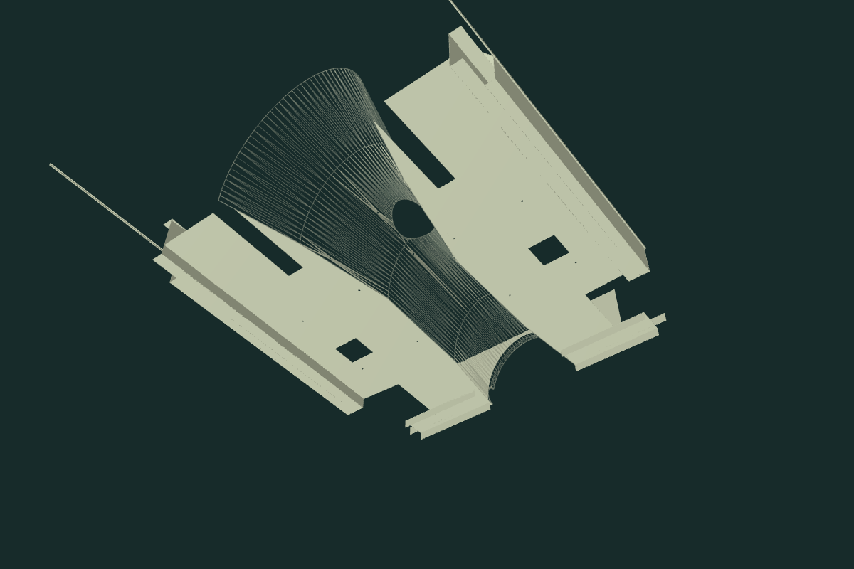
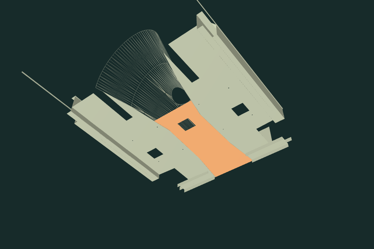
The new sheet exposes significant overlaps with independently placed mechanical references. No extra holes or pose changes conceal these discrepancies. They are not actual-car interference measurements.
| Current source | Sheet overlap |
|---|---|
| Gearbox extension | 2,713.83 mm³ |
| Rear propshaft flange/yoke | 769.25 mm³ |
| Rear axle housing | 2,356.99 mm³ |
| Differential carrier | 11,068.53 mm³ |
The scoped report records further source contacts and labels optional historical comparisons. These separate intersections must not be added as a single physical overlap volume. Native validity and an open square aperture do not verify tool access, operating clearance, axle travel, weld strength or a replacement procedure.
A separate outer rear bulkhead
The rear floor now has a separate outer heelboard or “shut panel” behind the retained inner panel. The manufacturer distinguishes BMH8005 inner, BMH8006 outer and AHA7203 complete rear bulkhead. First-hand factory assembly photograph BK shows the broad outer panel and its openings. Supplier photographs support a central arch and two lower side notches; they supply no fitted dimensions.

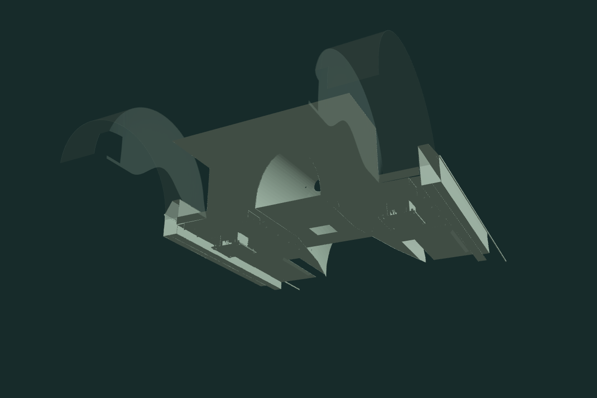
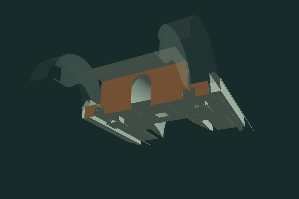
Construction estimates: the panel sits 50 mm behind the inner heelboard, with 1.5 mm projected-Z gauge and 16 mm upper/lower returns. Its central arch is selected 180 mm wide with a 430 mm spring-line height; lower notches are 100×70 mm. The existing stepped body-width outline and raised-floor underside supply reference boundaries. None is a measured pressing, normal steel gauge, factory seam or cutting template. The upper return touches the floor underside in this drawing; it does not establish a welded load path.
The retained front-eye axis is at Z=-457.2 mm; the inner heelboard is at Z=-702.73 mm, a 245.53 mm station difference. Neither is a supported fitted body survey. The new outer panel remains over 200 mm from each existing generic body-box source. No long bridge, relocated hanger or receiver map is invented to close that gap. The AHA7210 supplier photograph shows a small angle-shaped reinforcement; it is a separate role, not identification of the existing box envelope.
The full native assembly retains all 13 preceding mesh records and native volumes and adds one connected panel, giving 14 groups/23 valid solids. The central arch and both lower notches remain open through the returns. Native checks report the floor contact, explicit hanger distances and scoped neighboring-source overlaps. Seats, eight floor bores, sills, wheelhouses, springs, driveline and all existing assembly anchors stay.
Workshop connection: compare the inner and outer panels with the hanger/body registration finding. Isolating a welded panel explains the architecture. It does not verify bracing, cutting, weld order, body alignment, spring support, loaded clearances or a replacement/removal path. Actual hidden reinforcement, notch roles, holes, welds and repaired condition remain unknown.
Put the rear cockpit floor above the axle region
The previous low floor and tunnel extended almost to the rear axle. Their rear boundary represented the wrong floor level. First-hand photographs of BMH assembly show the main floor meeting a forward heelboard, with raised rear cockpit sheet continuing toward the boot. BMH distinguishes CZJ568 with the rear cockpit floor from BMH8058 without it.
The main floor, central sheet and tunnel now end at the existing wheelhouse-front estimate, body Z −0.83. The heelboard follows that boundary and its mouth follows the local tunnel section. A raised sheet joins the retained boot-floor front at its existing height and width. The underfloor crossmember keeps its section but moves beneath the new low-floor rear edge. Seats, eight floor holes, hanger pockets, wheelhouses, boot floor and the complete driveline keep their poses.
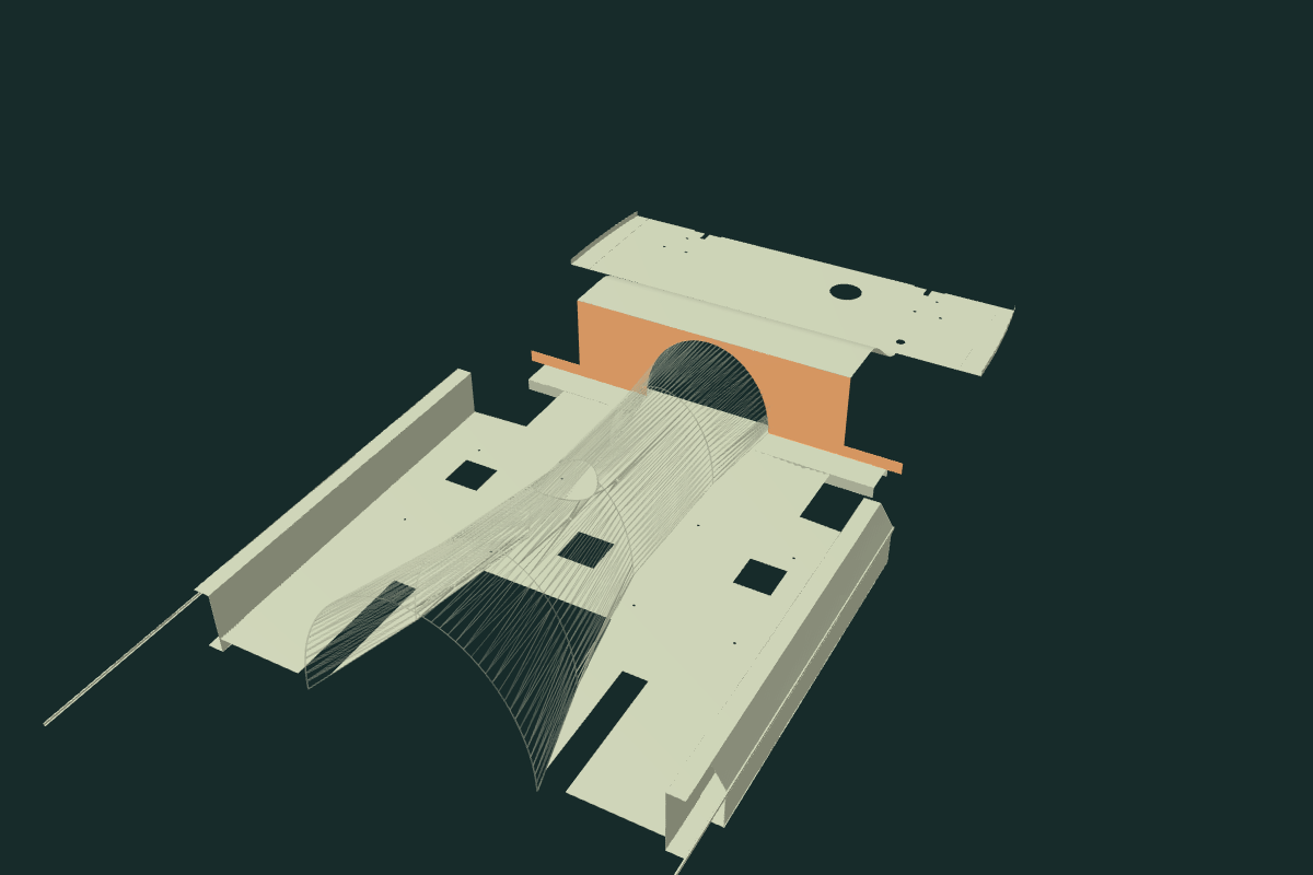
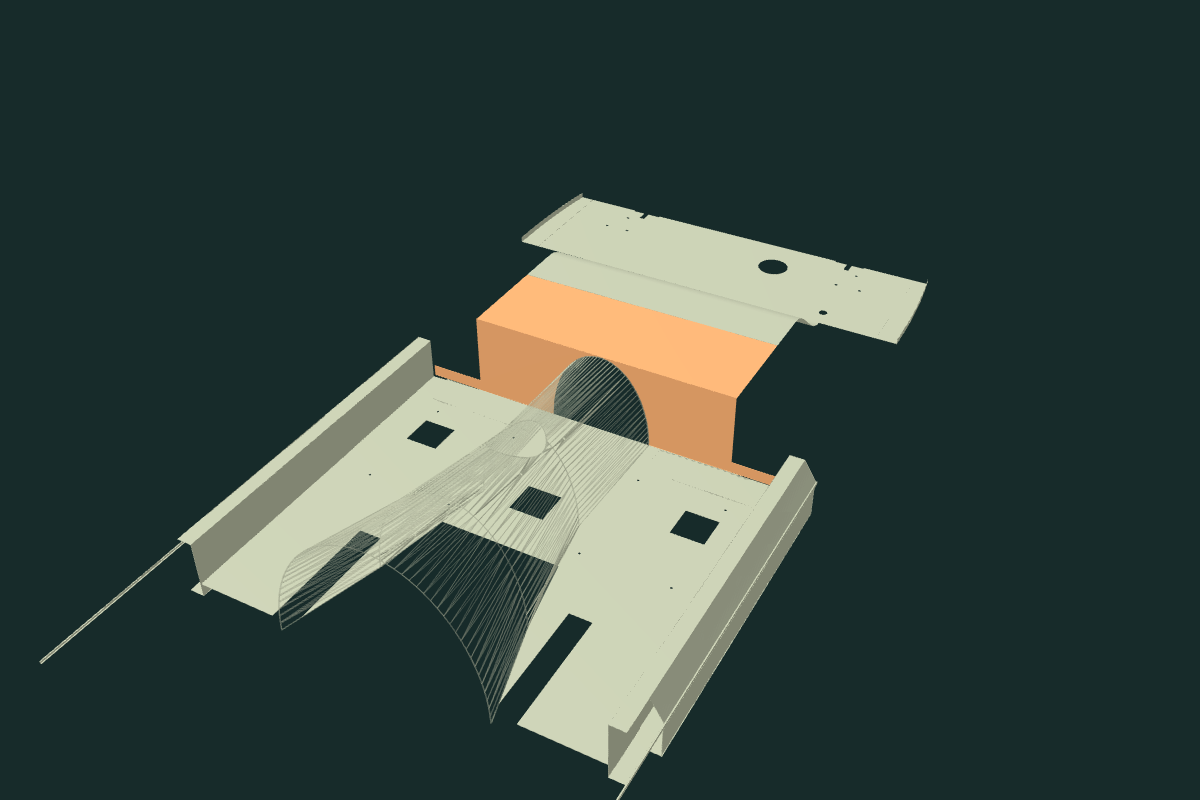
The numerical transition follows a prior model estimate. No applicable dimensioned 1500 body-alignment chart was recovered in the bounded search. The raised height, width, gauge and joints also remain estimates. Their source contacts do not establish welds, spring-hanger registration, axle travel, loaded strength or verified removal paths.
| Source overlap | Earlier | Current |
|---|---|---|
| Rear propshaft yoke | 769.25 mm³ | 0 |
| Rear axle housing | 2,356.99 mm³ | 0 |
| Differential carrier | 11,068.53 mm³ | 0 |
| Gearbox extension | 2,713.83 mm³ | 2,713.83 mm³ |
The forward gearbox/body discrepancy persists. Scoped rear checks also record 76.20 mm³ of heelboard/wheelhouse intersection on each side; panel seam ownership remains unresolved. The complete native report separates these drawing relationships from fitted clearances.
Broad floor wells and transverse pressings
The full-floor and half-floor replacement photographs show formed front wells and transverse channels. Both side floors now carry this architecture, replacing the flat sheet fields. The selected well is 190 × 350 mm and 8 mm deep; five transverse bead envelopes per side are 3 mm deep. These dimensions, radii, stations and the mirrored opposite side are construction estimates.
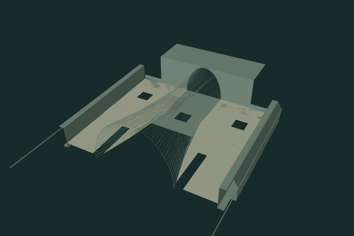
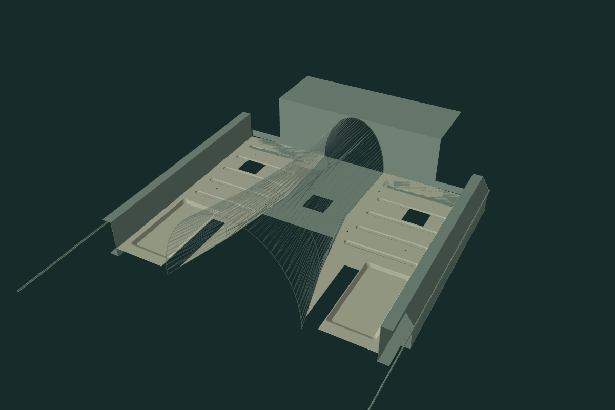
Each panel is a connected skin with an exact 1.5 mm vertical section in the drawing. This is a projected section, not verified normal metal gauge or sheet development. Original outlines, eight seat holes, rail passages and hanger openings remain the mask. An inherited opening can interrupt a bead; that interruption is not a recovered factory stamping. The flat material beside the seat holes stays.
Native checks preserve the projected panel volume, probe the wells and their open undersides, sample section thickness across slopes and confine changes to the declared pressing footprints. Eleven other source meshes and all earlier metadata stay. Central floor, rear step, seats and mechanical poses are unchanged.
Reinspection of owner underside photos and donor gearbox photographs did not supply independently scaled case/floor coordinates. The existing gearbox-extension overlap remains open. The floor pressings do not establish fitted identity, loaded seat support, strength, working clearances or a replacement procedure. No new drain, plug or weld map is inferred.
Native export
Validation covers 16 valid solids, retained seat bores with neighboring material, open tunnel bottom/lever mouth/tube reliefs, shared floor/tunnel stations, open sections, metric placement and fixed body inspection ownership. Per-part CAD intersections against the existing rear-axle STEP at its declared body transform are zero for these seven source parts. This is static comparison geometry, not a minimum or fitted clearance/travel result.
The gearbox body-gaiter study now follows this curved tunnel with a separate hollow cuff, flange and retainer. Four shared construction holes follow estimated local surface normals; they are not factory body coordinates or a drilling/repair template. Six non-tunnel source meshes remain unchanged.
Bounded sill sections at the rear arch
The former inner sill ran back beyond the rear axle station and below the visible outer sill. Its rear end passed through the rear tyre reference. The revised inner sill stops at the existing rear-arch front, Z=−.82 body units, and reaches the existing footwell front at Z=+.35. Its lower return now shares the outer sill’s retained Y=.30 datum. These are coordinated construction boundaries, not owner measurements.
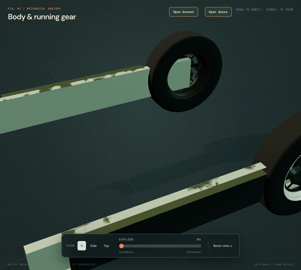
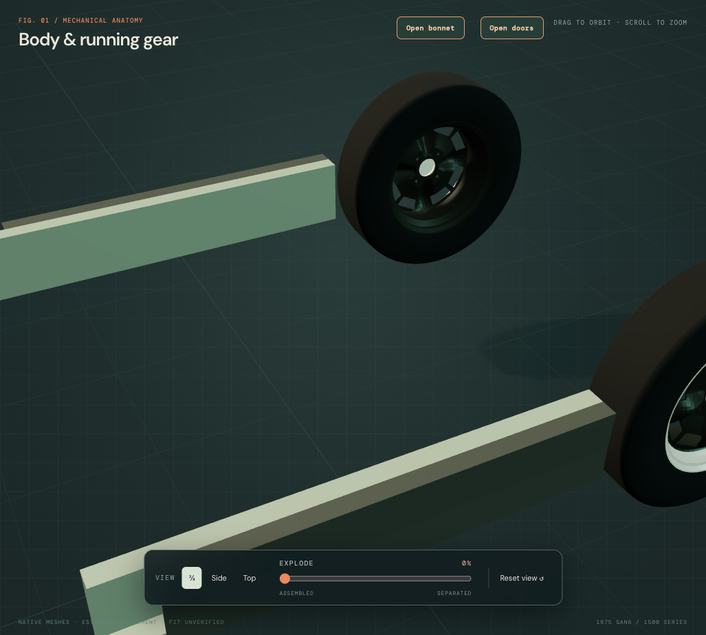
Paired native outer skins now replace the browser-only skins and top ribbons. Their cambered outside surfaces follow the retained visible body profile; top and lower returns meet the inner return edges at X magnitude .71. Outer fronts retain Z=.23, leaving the forward lower-wing/footwell closure to reconcile. The estimated 1.5 mm projected sections, open ends, joints and mirroring are reference construction. They do not reconstruct fitted hems, laps, welds, strength or corrosion.
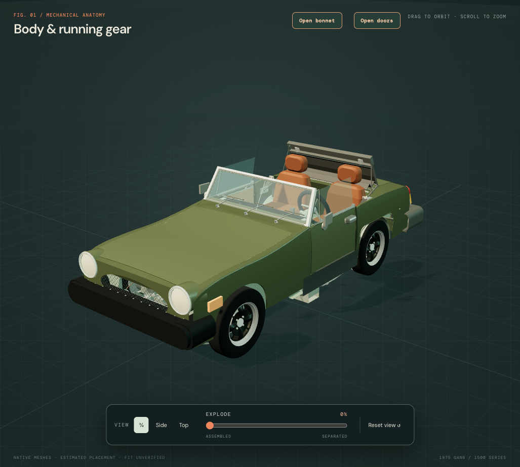
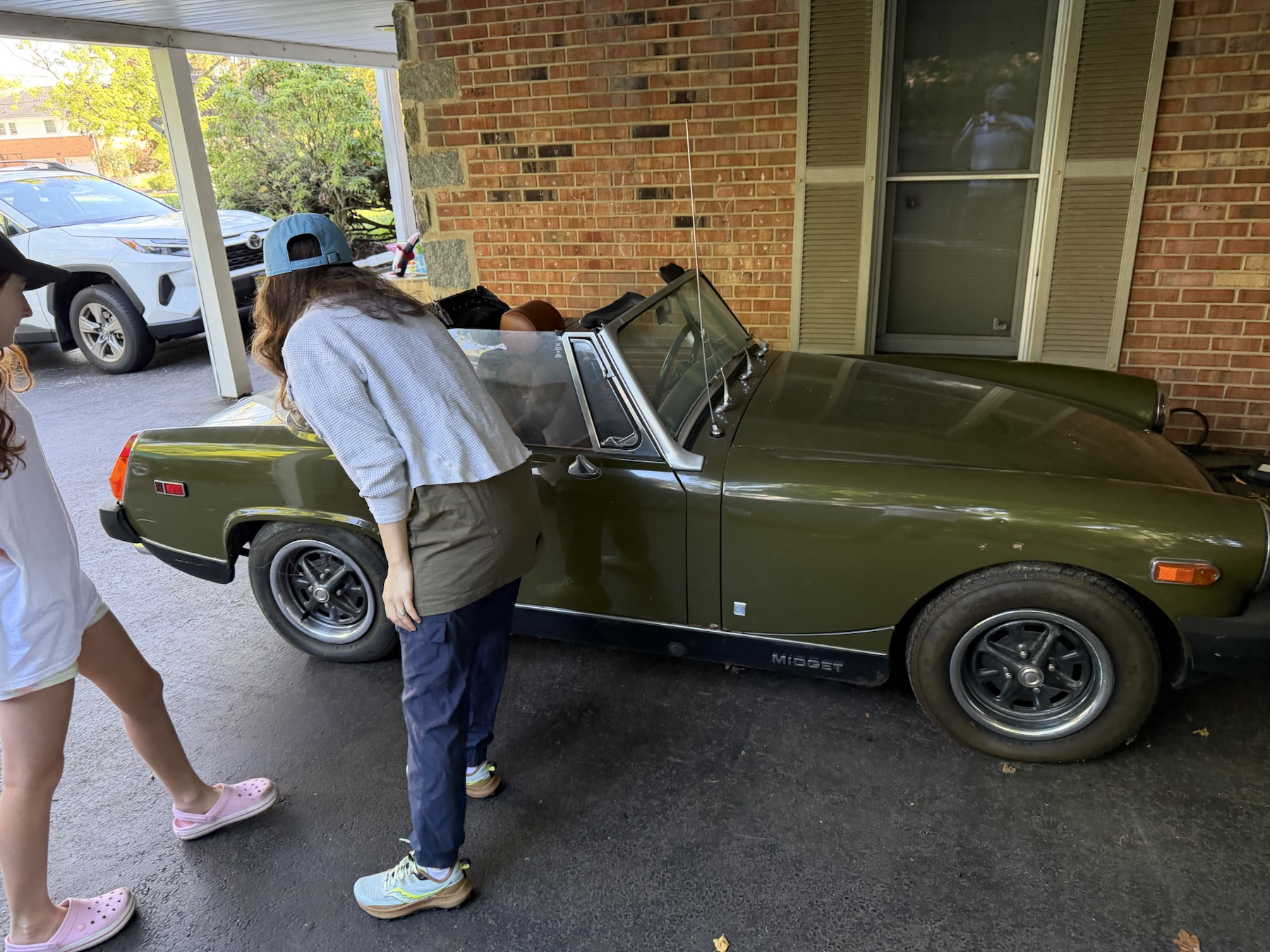
IMG_6329 and IMG_6341 establish the visible black rocker, door aperture and rear wheel-opening relationship. British Motor Heritage distinguishes CZJ176/177 inner sills, floors and footwell panels. Its skin-panel table distinguishes 1975-on twin-jacking-point CZJ694/695 outer sills from earlier applications. None identifies this car’s installed repair panels or supplies the modeled sections. No jack apertures or reinforcement locations are inferred.
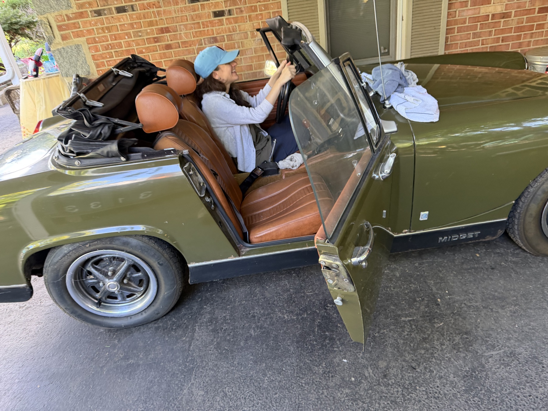
What the checks establish: the nine source groups contain 18 valid positive STEP solids; five former mesh payloads remain identical. The old inner-sill/tyre source overlap was about 3,221 mm³ per side; the revised inner and outer sills have zero static overlap with the unchanged tyre sources. Return-edge material witnesses and all eight retained seat-floor axes pass. This does not verify fitted wheel clearance or suspension travel.
The unchanged floor still overlaps each rear tyre reference by about 2,326 mm³. Rear floor, wheelhouse and seat/body registration need reconciliation together; the sill revision does not resolve that interface. No seat holes or floor corners were moved to erase it. These are model discrepancies, not evidence of interference on the actual car.
All sill/body groups remain fixed during illustrative separation. Isolation exposes sections; it does not make welded panels detachable. No cutting order, bracing, support or jacking point, repair suitability, weld schedule or verified replacement/removal path is established.
Seats, floor and wheelhouses together
The former seats sat mostly behind the modeled door openings. IMG_6341 shows the cushions occupying the doorway, with rear edges near the B-post. Both complete seat assemblies now move forward by an estimated 317.5 mm: upholstery, headrests, frames, runners, catches and fixing references retain their shapes and relative positions. The eight floor-hole references follow the same translation.
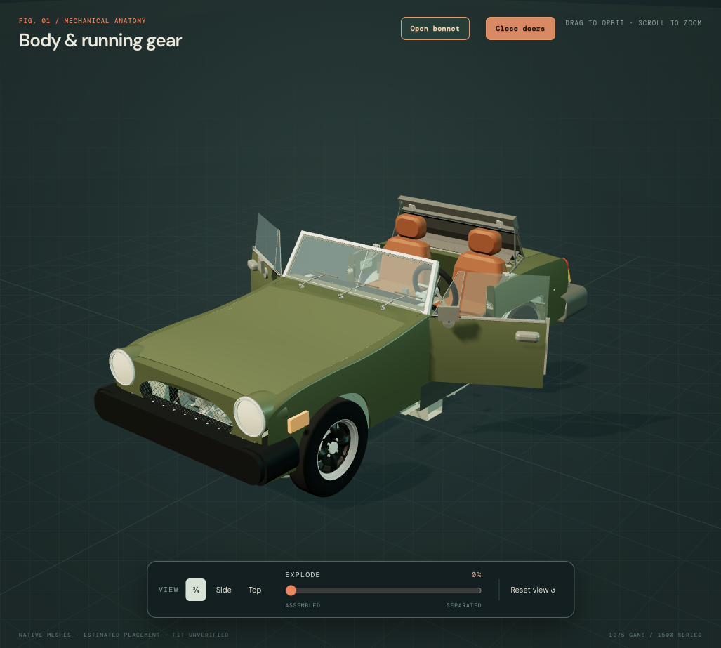
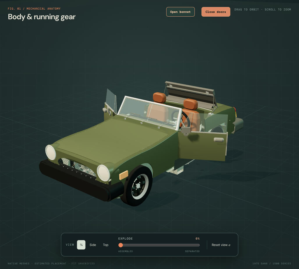
The selected shift aligns the retained native cushion’s rear extent with the existing estimated B-post boundary. It is a coherent construction choice, not a calibrated measurement from the photograph, a factory seat station, an actual rail setting or an ergonomic fit. Seat dimensions, X/Y stations, recline and body aperture stay. The opposite seat repeats the choice without proof that both fitted seats share an adjustment.
The surrounding rear floor
Rear floor corners now step inward to the retained inner-wheelhouse plane, X magnitude .47. The wheelhouse lower webs extend from their former axle-height chords down to the retained floor at Y=.35. Wheelhouse radius, wheel/axle poses, roof and reliefs stay; no wheelhouse material is removed. Native inner/outer sills, tunnel, spring hangers, body restraints, folded hood and the engine/body frame remain at their previous references.
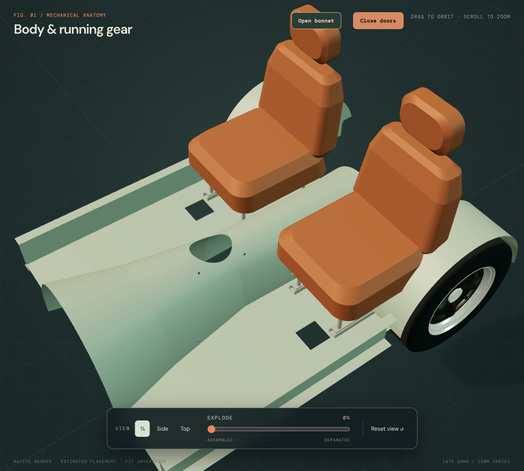
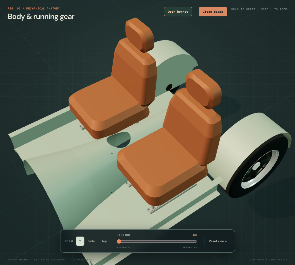
British Motor Heritage’s rear-body drawing distinguishes inner wheelhouses, wheelarch reinforcements and the rubber-bumper CZJ568 boot floor with cockpit rear floor. Its front/centre drawing separates floor and sill panels. Factory seat plates separate cushion, frame and runner roles. These sources establish assembly roles, not the new seat station, floor outline, wall skirt, fitted welds or body dimensions.
Checks and unresolved interfaces
All 20 native upholstery/support groups retain volume and bounds under the same rigid translation. Four STEP exports contain 162 valid positive solids. Seven cabin and 16 rear-body mesh payloads remain identical. All eight new floor bores are open with neighboring floor material; witnesses confirm material on both sides of the shared floor/wall boundary.
The floor/tyre source overlaps of about 2,326 mm³ per side and the seat-frame/wheelhouse overlaps of about 1,404 mm³ per side are now zero in the sampled static sources. The independent heelboard still overlaps each wheelhouse by about 59.5 mm³; its join/lap and wider rear-body registration remain unresolved. These results do not prove actual-car clearances, loaded support or a collision-free seat adjustment.
Workshop limit: no actual holes are specified for drilling, and the new floor outline is not a cutting template. Body/belt anchors remain untouched as unverified comparisons; belt compatibility, seat-slide/recline travel, door clearance, fixing strength, safe support and a verified seat or floor replacement sequence are not established. General separation and the door pose remain illustrations.
Round the visible seat padding
The cushion, backrest and headrest on both seats now use smooth interpolating native surfaces through the existing photo-led section wires. This replaces the sharp horizontal bands left by the old ruled lofts. Owner IMG_6341 shows rounded padding and shoulders, without calibrating an exact foam or cover shape.
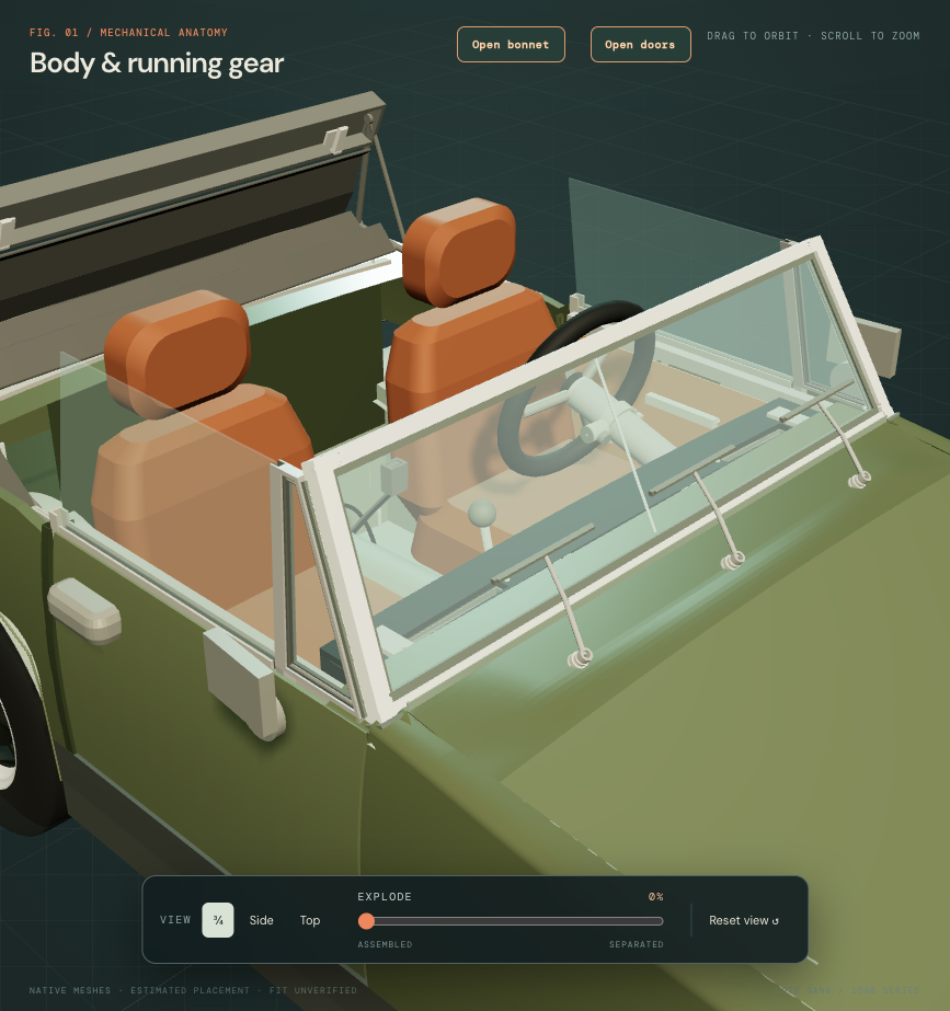
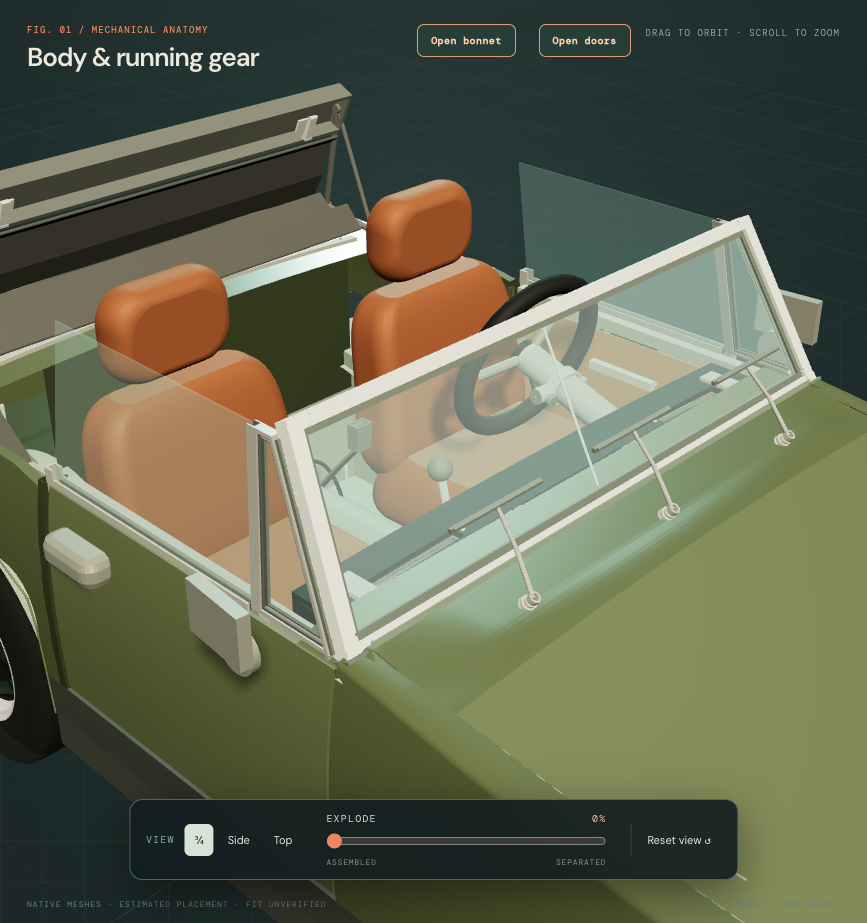
The source sections, lateral/fore-aft seat positions and cushion support datum stay. Interpolation adds estimated crowns up to about 8.8 mm beyond the old faceted bounds; that value describes the drawing change, not padding measured on the car. A small interpolation undershoot is trimmed at the inherited cushion lower plane, preserving its construction support boundary.
Six valid closed native upholstery solids replace the former six. Native/mesh volume agreement, retained section-boundary witnesses and the lower support plane are checked. The browser keeps the surrounding assembly positions and loads the new surfaces at the existing metric scale. These checks do not establish fitted foam dimensions, fabric thickness, loaded support, headrest guide/post connections, adjustment or a removal path. Both seats still repeat an assumed common shape.
Recessed seating faces and raised bolsters
The previous whole-car seats were smooth closed volumes. Both cushions and backrests now have broad, curved longitudinal ribs within recessed seating faces, leaving the existing outer flanks as raised bolsters. Your IMG_6341 supports this visible structure. The opposite seat repeats the reference shape; matching adjustments or upholstery are not established.
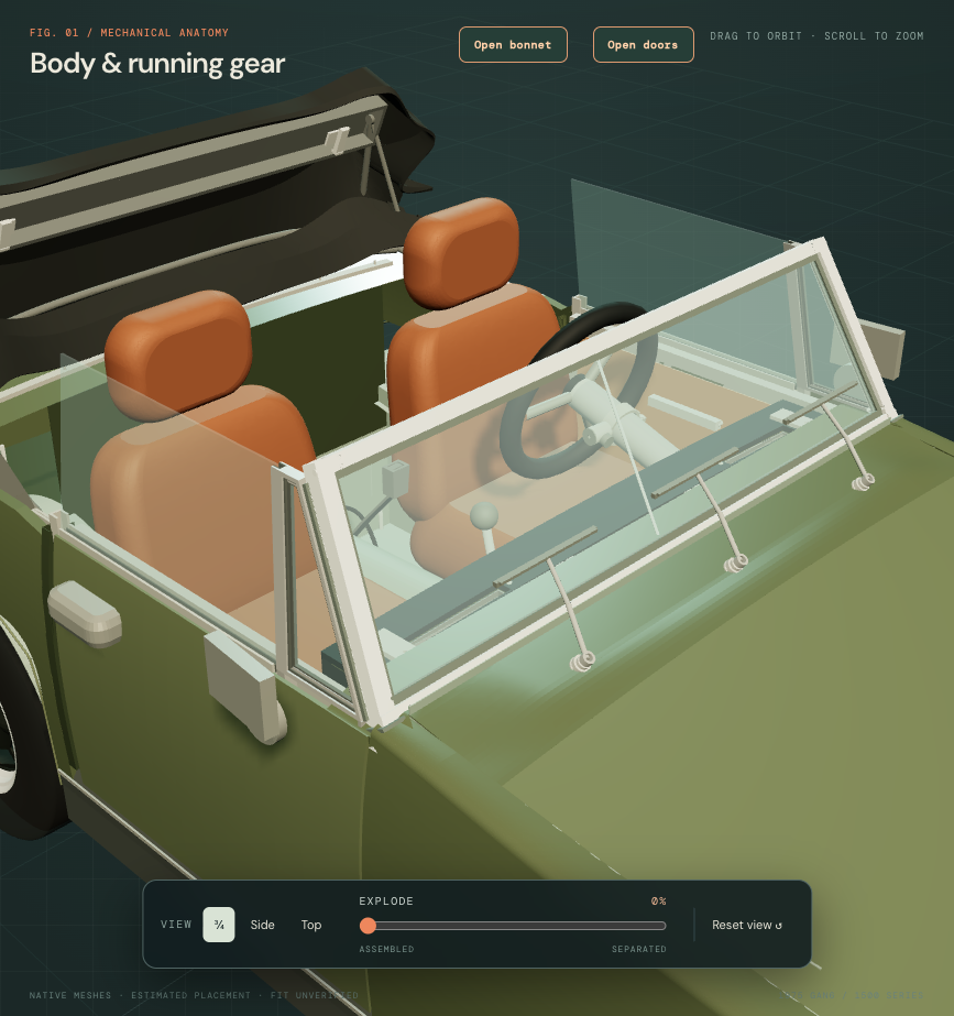
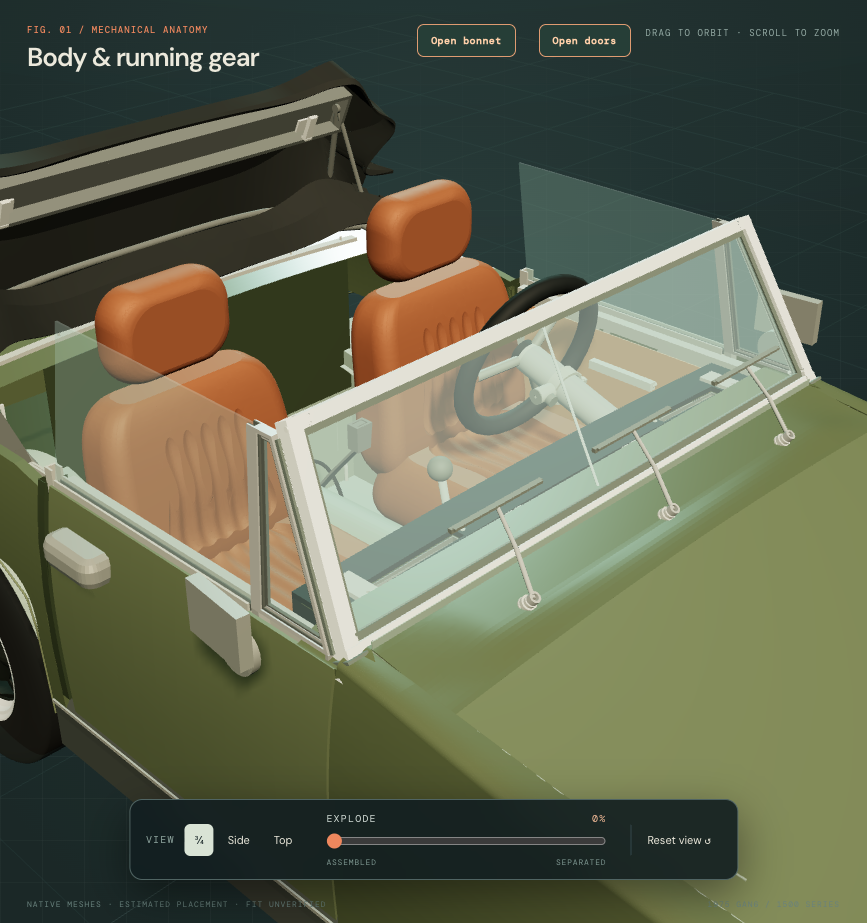
The outer section controls, cushion support plane, headrests, runners, frame and body anchors stay. The drawing uses an estimated 38.1 mm rib pitch, 5.93 mm peak-to-trough relief and nominal cushion trough about 24.6 mm below the retained top plane. These values describe the construction, not dimensions measured on the car. Rib count, panel outlines and depth remain photo estimates; no seam count or original seat identity is selected.
Four native seating solids change; the two headrest meshes stay identical. Relief is formed by open cutting surfaces, with no separate foam or cloth layer implied. Native validity, single closed shells, open-face witnesses, mesh-volume agreement and the retained lower support plane are checked. Earlier smooth-surface checks describe their historical revision.
Workshop connection: the shaped cushions and backrests remain linked to the existing complete seat/support assembly. Their illustrative separation does not verify cover removal, foam construction, headrest guides, slide/recline travel, fixing access or a collision-free doorway removal path.