Windscreen frame, seals and body mounting
The former thick glass slab and solid posts are replaced by separate open glazing channels, pillars and body legs, seals, corner reinforcements, center rod and fixing roles. A tapered screen and splayed pillars now follow the raised door-glass lean. Pane local height and the door-glass base/lean remain. A photo-led rake correction now rotates the frame about the former lower pane center; fitted dimensions remain unverified. This assembly adds cabin and wiper-access obstacles; it does not establish a fitted windscreen or a removal route.
A shared shallow-bow depth comparison
The existing donor photographs and owner IMG_6329/6341 provide outline and installation context. They do not recover a three-dimensional glass surface or a metric bow. The new 20 mm center advance is an explicit construction hypothesis, with a smooth transverse curve that becomes flat before the retained pillar ends. There is no vertical bow in this model; actual compound curvature remains unresolved.
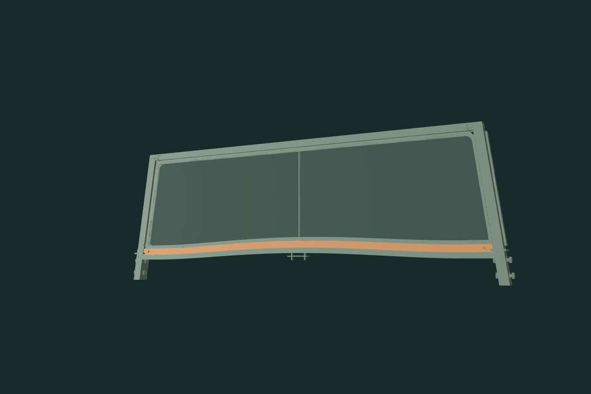
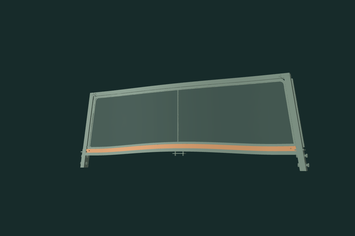
The pane, glazing rubber, top and bottom open channels and unloaded body lip share one depth curve. The existing projected outline, rake, origin, outer terminal material, pillar legs, quarterlight seal lines, corner fixing neighborhoods and independent body stations stay. The center rod and its brackets move 20 mm along screen-local forward; each hood-bracket comparison moves by the curve at its center. The independent center-body packing and parked hood stay, so those interfaces remain unregistered.
The scoped drawing audit records 26 positive contacts after the change, compared with 25 before. New pairs include the pane against two parked wiper arms and the lower channel against the bulkhead. Other blade, rail, seal and body contacts also change. These are unresolved source relationships, not actual-car interference or fitted clearance measurements; neighboring sources remain held. Evidence and construction choices ↗
The 5 mm projected pane depth gives a slightly varying normal section. No glass marking, optical or manufacturing specification, compressed seal fit, rod tension, hood engagement, working wiper sweep, installed clearance or verified replacement procedure is established. No body cut, shim, receiver or attachment bridge is added to close source gaps.
The sections below retain the earlier outline, assembly and rake studies. The shallow-bow comparison above supersedes their flat-depth geometry.
An arched lower frame and rounded glazing corners
The original photographs of RW22163, described by its seller as a 1978 Midget 1500 donor, clearly show an arched lower rail and rounded upper glazing corners. The earlier outline revision replaced the straight lower edge and square upper pane corners. The pane, glazing seal, lower channel/body lip and center rod/lower bracket change together; the eleven other source groups, including pillars, body legs, top rail and quarterlight interfaces, stay.
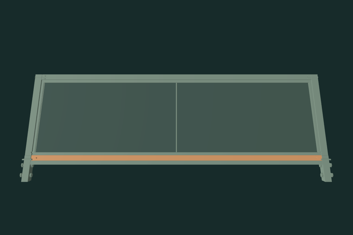
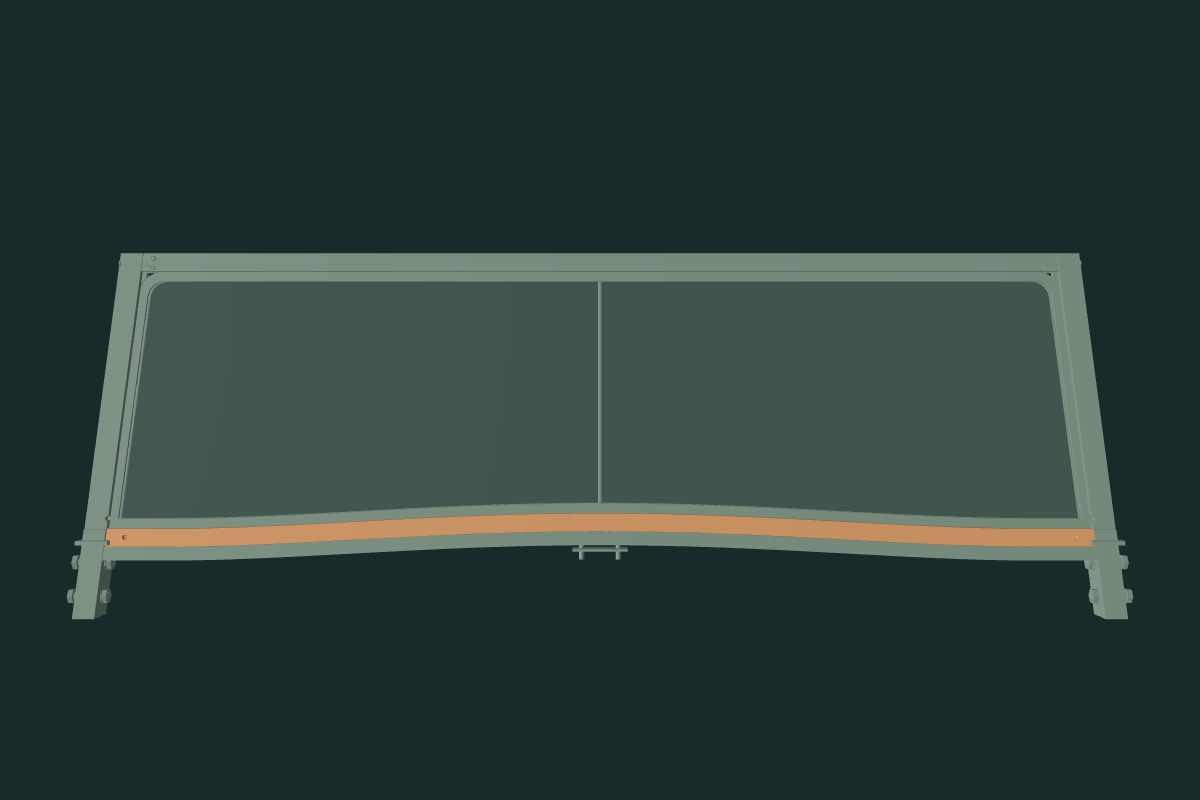
The selected 18 mm middle rise, 70 mm flat end regions, quartic arch and 25 mm upper pane-corner radius are unmeasured construction choices. No metric scale or three-dimensional glass bow is recovered from the photographs. At this earlier stage the pane remained a 5 mm flat-depth display solid. The current bow comparison above supersedes that display shape; actual glass curvature and a true template remain unresolved.
The center rod shortens 18 mm at its lower end; the lower bracket/nipple follows that proposed arch while the upper endpoint stays. The separate center-body packing and fixings remain at their old independent station. Their connection is unregistered: no receiver, shim or loaded support is invented.
The audit finds 26 positive source contacts before and after, with some volumes changed. Lower-channel/scuttle overlap changes from 16368.429770 to 22750.525714 mm³; body-lip/bulkhead overlap reduces from 10848.107017 to 4628.820232 mm³, while body-lip/scuttle gains 8411.884697 mm³. These are static drawing conflicts, not actual-car interference findings. Wipers, scuttle, body and door sources are not moved or cut to conceal them.
Inspect the assembly
Screen and quarterlight alignment
The old rectangular screen had parallel side pillars beside door glass that leaned inward. Owner IMG_6329 and IMG_6341 support a tapered surround and quarterlight alongside the pillar; the factory illustration also distinguishes those surrounding pieces. A shared reference construction now tapers the pane and splays the pillars, open channels and seals. The quarterlight front edges follow the pillar seal line, while their rear divider, the main door panes, carriers and regulator references stay in place.
The new pane widths are approximately 1143.026 mm at the bottom and 1059.795 mm at the top, replacing the prior 1075.267 mm rectangle. These are construction estimates, calculated from the existing door-glass base and inward lean. They are neither owner measurements nor factory glass specifications. Screen height 287.867 mm, center and −0.27 rad rake remain schematic; no overall-body width is used to rescale the car. That earlier pane was flat and 5 mm deep for display.
Body legs, foot grommets and round fixing envelopes follow the revised pillar positions. The center rod, its brackets and center-body fixing comparison, and the hood-bracket geometry are retained. No receiver, shim or body aperture is fabricated to force a fitted mounting. Both the seal line and the visible quarterlight/frame overlap are unloaded reference geometry; door travel, glazing curvature, compressed sealing, hood fit and removal paths remain unresolved.
Evidence already supplied
Factory architecture and configuration differences
Factory p.272 distinguishes glass and complete-screen branches, including North American high-impact laminated comparisons. P.273 separates pillars and top rails, with NA/Sweden branches distinct from other markets. P.274 separates bottom rail/corner reinforcements, center rod, pillar seals/retainers, body seal, center packing and foot grommets. No fitted part number, glazing marking or seal branch is selected.
Moss printed p.55 / PDF p.73 supplies four upper/lower leg fixing roles and two center-body bolts. The factory list gives one HPS408 center screw; that count difference remains unresolved. The six upper-rail screw roles and twelve retainer-rivet cues use estimated maps. Hardware is threadless and unloaded; the model does not establish fitted lengths, engagement or tightening.
Mounting and surrounding obstacles
Four shared bores pass through the new pillar legs. No A-post receiver, shim stack or body penetration is invented to accept them. Separate foot grommets indicate the missing body-crossing relationship. The center-rod brackets and packing expose another body joint; mirrors and sun visors remain incomplete. Hood-fastener brackets provide comparison boundaries without fitted header/latch engagement.
The anchored-rake source comparison still intersects the independent body references: the lower channel meets the scuttle by about 16,016 mm³, each pillar meets its scuttle corner by about 1,626 mm³, and the unloaded lower seal meets the bulkhead by about 10,848 mm³. Smaller contacts are recorded in the current source and validation metadata. These are reconstruction discrepancies, not actual-car interference measurements. No receiver, shim, body cut or body relocation is fabricated to hide them. The subsequent apron reconstruction changes the central shroud and wiper row while the windscreen and front-footwell exports remain held; see the scuttle study for the independent body-frame gaps.
Workshop use and remaining gaps
The glass, frame and carried seals move together in the inspection display, while body-fixing and packing comparisons remain independently selectable. That separation is illustrative. No verified release order, safe frame support, glazing installation procedure, torque, rod tension or windscreen withdrawal path is established. Reconcile the actual receiver positions, glazing curvature, loaded seals, body packing and neighboring wiper/door/hood relationships before treating this as a fitted replacement rehearsal.
A photo-led correction to the whole frame
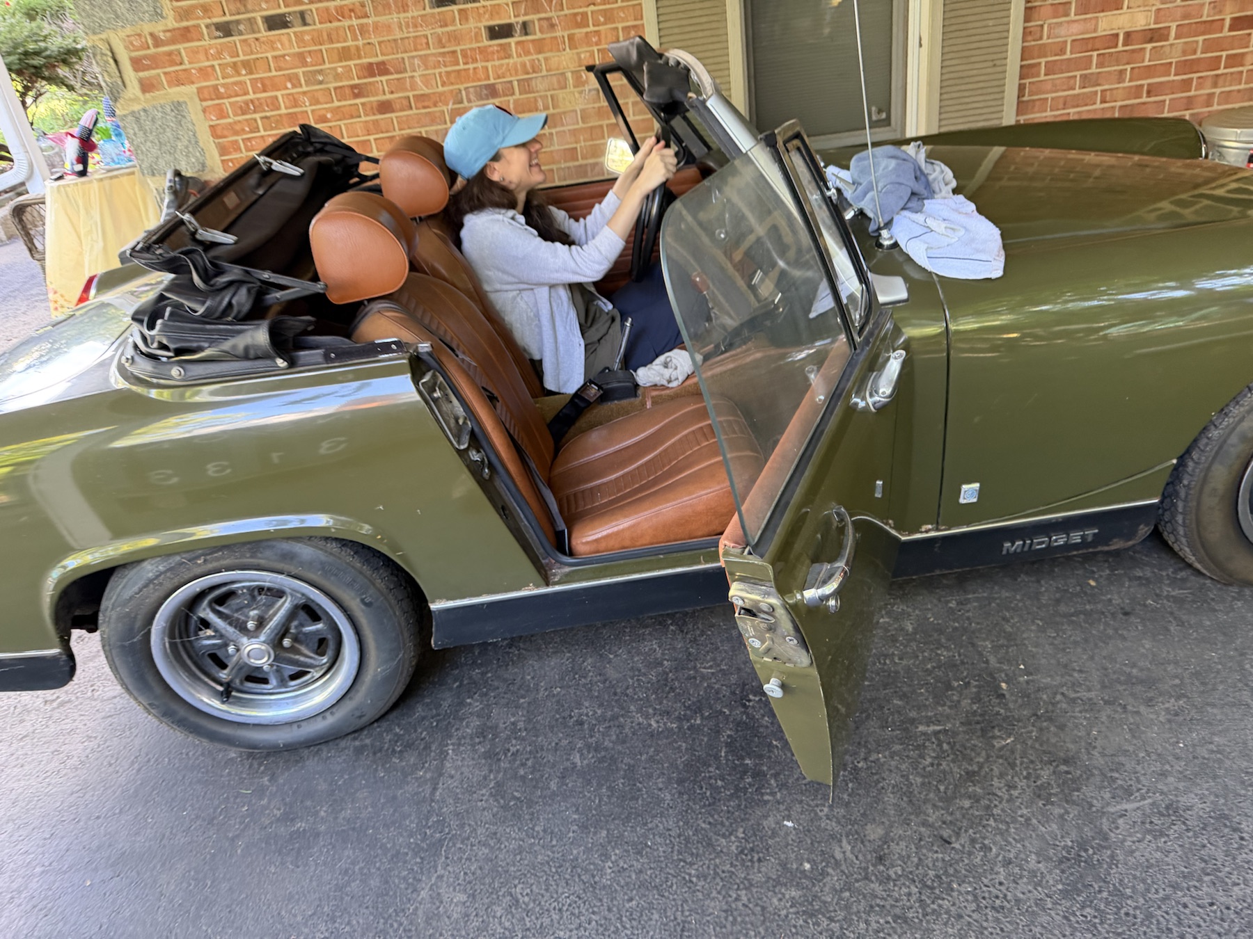
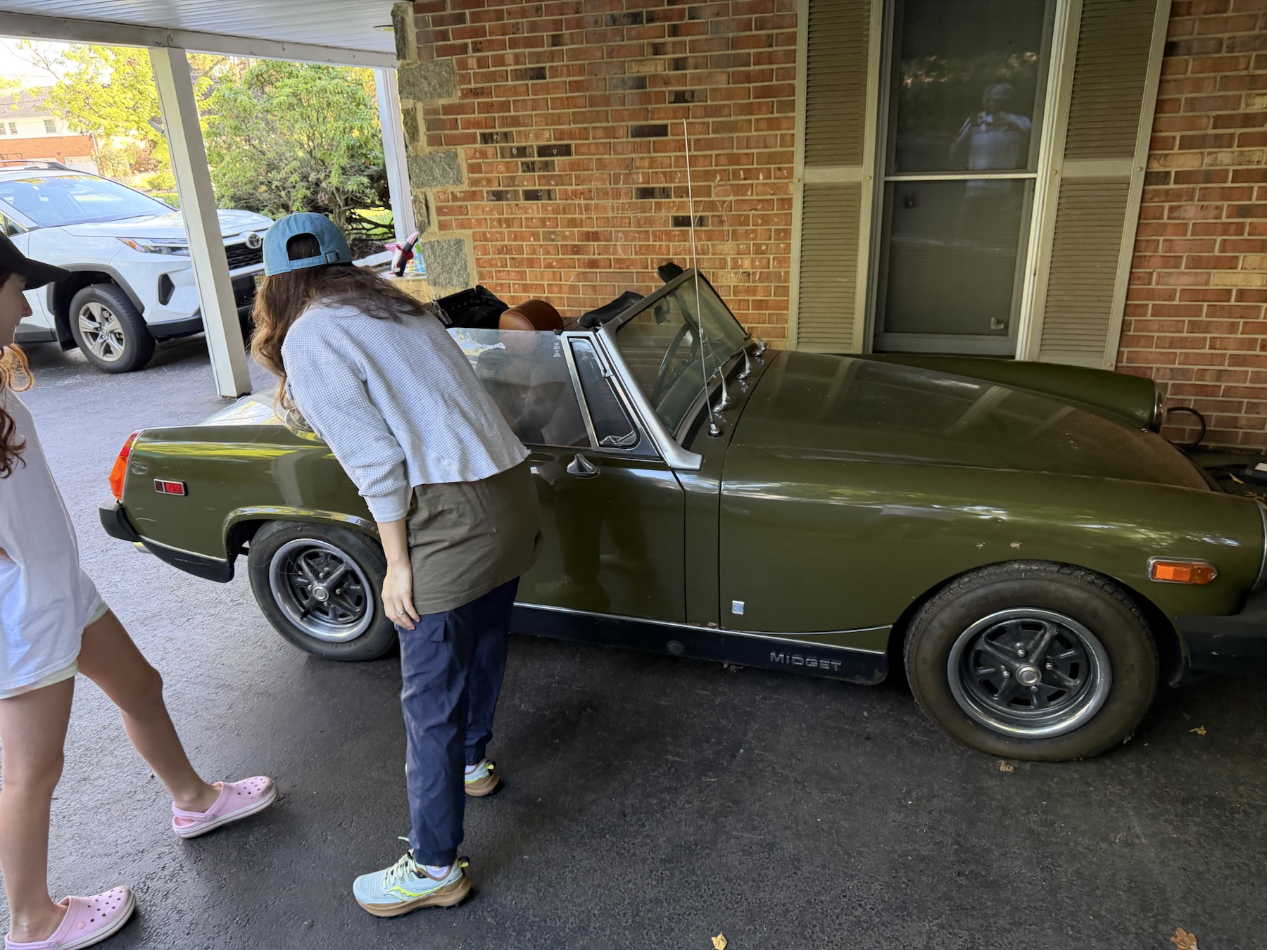
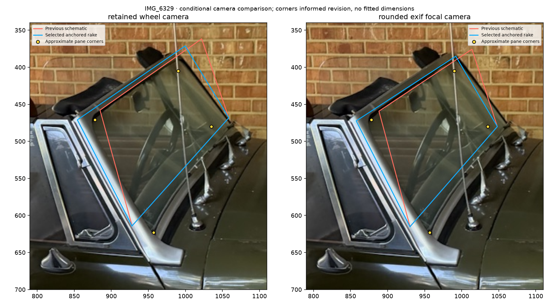
IMG_6329 exposes all four approximate inner-pane corners. Under the retained wheel-derived camera and a separate rounded-EXIF-focal camera hypothesis, the former −0.27 rad schematic is too upright. Both diagnostic fits suggest about −0.49 rad (28.1° rearward from vertical). Their width solutions disagree substantially, so those fitted widths are not applied. IMG_6341 provides qualitative cross-view context, not an independent dimensional survey.
The selected construction rotates the whole screen/frame from −0.27 to −0.49 rad around the old lower pane center. That center’s body Y/Z coordinates, the 287.87 mm local pane height, and the existing door-glass base width/lean stay. Derived frame origin becomes approximately Y 1004.28 / Z 12.99 mm. The upper pane center moves about 58.69 mm rearward and 23.44 mm lower. These are model changes, not measured fitted dimensions. Pane widths continue to follow the held door-glass lean; no uniform width rescale is applied.
All seventeen native groups follow: glass, rails, pillars/legs, seals, rod, packing, hood brackets and fixing roles. Both quarterlight front edges update from the same seal-line construction; main door panes, rear dividers, door hinges, body, wipers, engine and bonnet stay. Frame/body receivers, compressed seals and working door/hood/wiper relationships remain unverified.
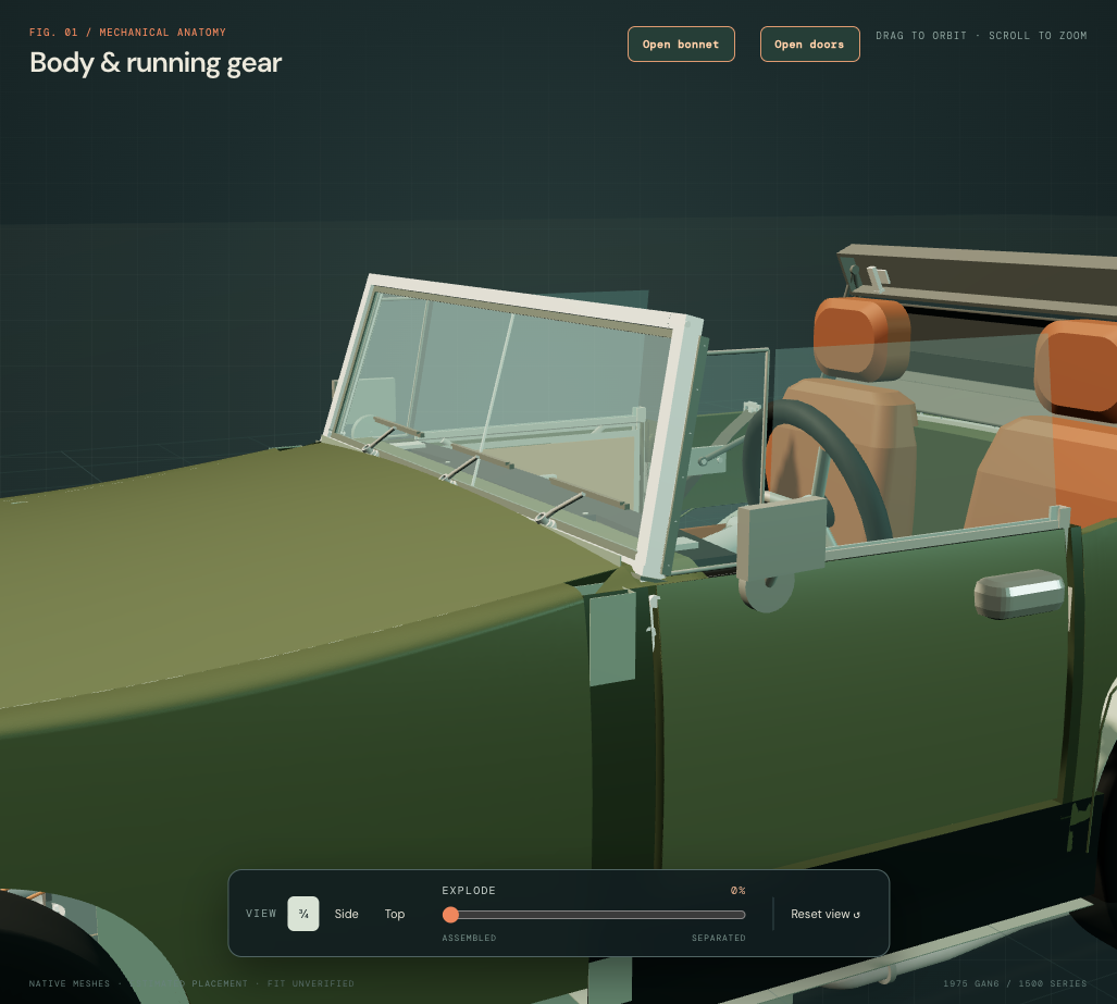
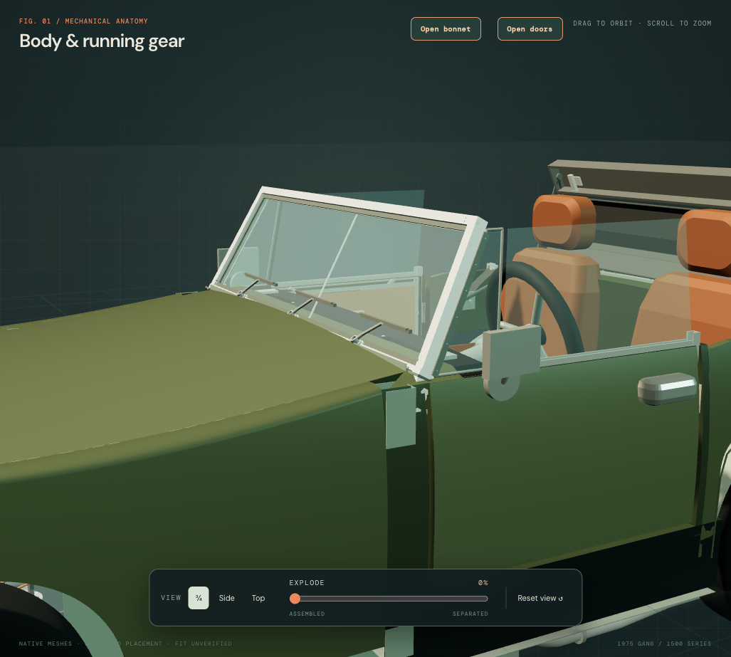
The factory windscreen drawing establishes component/configuration roles, not an installed rake dimension. No factory rake, curved-glass outline, fitted body survey or verified replacement procedure is inferred from its exploded perspective.
Current broader apron and bonnet relationship ↗ supersedes the earlier central-shroud contact sample. Screen source geometry stays; lower rail/seal and body receiver registration remain unresolved.
Interior mirror and early North American visors
The model now adds a separate interior mirror and paired sun-visor comparison assemblies. All seventeen earlier bowed-screen, rail, seal, pillar, rod and bracket mesh records are retained. The exterior door mirrors have a separate owner-photo reconstruction and source history. These new assemblies have estimated dimensions and static mounting stations; they are not identified fitted parts.
Factory PDF 275 lists the BHA4960 dipping interior mirror and two RMP2307 screws to the windscreen rail. Factory PDF 291 distinguishes earlier AHA9694/9695 visors from the later CHA64/65 North American pair, with spherical washer AHH8799, spring washer AJD7721 and LNZ203 nut roles. Moss PDF 73, printed page 55, distinguishes visor and pivot-bracket branches through 1976 and from 1977, plus separate inner stay brackets. Its washer-order correction is retained as a supplier interpretation rather than a fitted assembly observation.
The mirror supplier’s rear photograph supports a rounded shell, flat stalk, joint boundaries and dip tab. The visor supplier’s photograph supports a padded panel, bent pivot rod and inner pin. The mirror listing’s 8 × 5 × 3 inch commerce dimensions are not a component drawing and are not adopted. Inspected owner cabin views supply surrounding context but no calibrated bracket map or fitted visor identification.
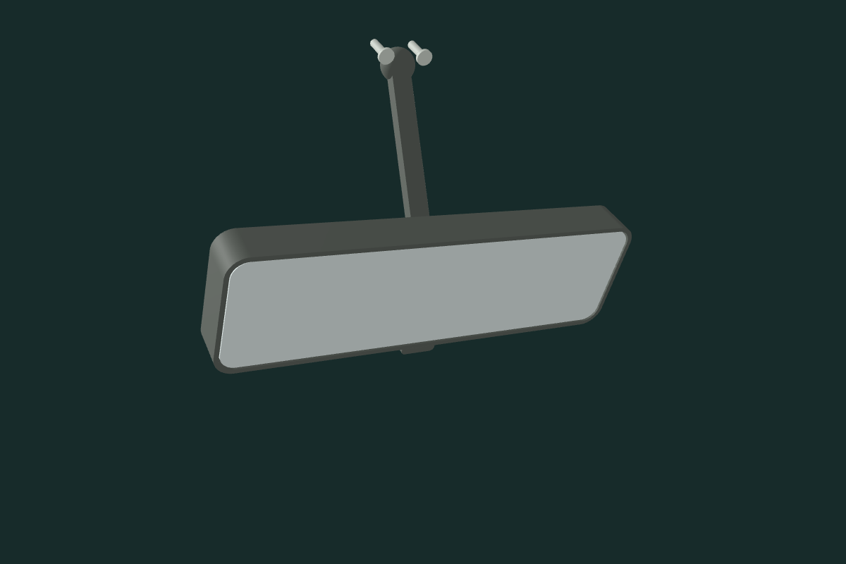
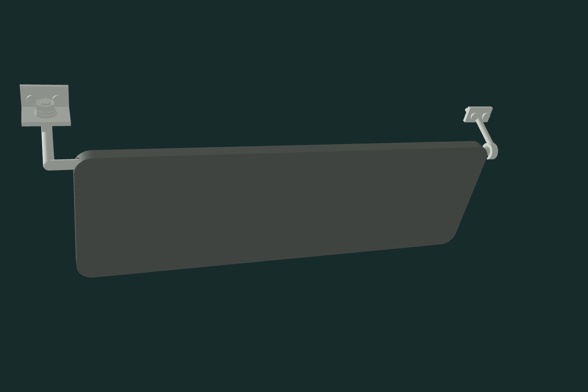
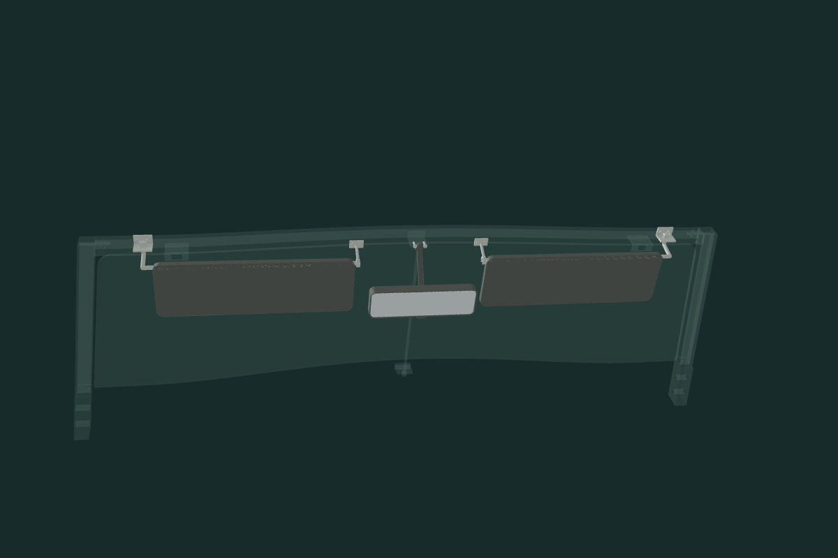
Estimated mirror head: 185 × 55 × 18 mm. Estimated visor envelope: 330 × 105 × 10 mm. Stalk, joint, rod, pad bore, bracket, washer, nut and fixing geometry is also estimated. The existing screen bow, rake, origin and neighboring sources stay. New bores are confined to new comparison parts; no receiving holes are cut in the old rails or brackets. Positive contacts and unresolved mounting gaps are recorded as source discrepancies. These boundaries do not establish fitted retention, breakaway strength, seal compression, glare protection, rearward field of view, hood/door clearance, regulatory compliance or an installation/removal procedure.