Behind the
parked blades.
A separate motor can, open gear case/cover, toothless drive/link, strap/packing, casing/grommet route, three wheelboxes and static spindle/arm/blade references now connect the engine-bay and cowl surroundings. This is a recognition model, not an operating wiper simulation.
Inspect the drive boundaries
Keep the factory branches separate
Factory PDF p. 221 explicitly depicts the three-blade system and separates motor/gear, rack/casing, strap/pad, grommet, three wheelbox/spindle assemblies, bushes, arms and blades. The two-blade configurations on pp. 218–220 are separate comparisons. The three-blade topology does not identify the actual motor suffix, wheelbox or arm/blade variant.
GEU708 supersedes the listed 37H2732 motor comparison, while the motor’s stamped manufacturer suffix controls internal service parts. The 37H6314/37H7738 wheelbox change at GAN6-156798 and later BHA5207/GWB164 arm/blade branch remain unselected as fitted. Catalog RTC702 rack stock length is not imposed as a calibrated route. Gear tooth count, ratio, sweep angle and electrical/park-switch variant are not assigned.
Owner evidence reconciled
IMG_6329 and IMG_6341 establish screen, frame and parked-wiper context; perspective, towels and occlusion limit the base/arm survey. IMG_6855 and IMG_6891 show a strapped cylindrical unit beside the heater on the expected motor side, without a readable motor number or complete tube/terminal map. The motor recognition shape follows that visible context and the factory drawing; hidden wheelboxes, routes and mount dimensions remain catalog comparisons and estimates.
Declared cowl construction changes
The prior lower-screen trim envelope was 1.38 × .045 × .060 body units at [0,1.03,.12]. It now measures 1.38 × .025 × .025 at [0,1.025,.082], behind the new estimated pivot band. This narrows the oversized trim reference without changing the screen pane, posts or upper rail. It is a construction alignment, not a measured frame, cowl or compressed-seal profile.
A thin body-side band has three estimated spindle passages. The motor-to-wheelbox casing uses a separate estimated bulkhead aperture/grommet at canonical [-.61,.96,.13] body units; neither that opening nor its identity is surveyed on this car. Three angled spindle axes and the parked arms/blades are construction choices. No operating plane, rack/gear engagement, wiped area, park angle, seal compression or loaded blade contact is verified.
Tube ends meet declared wheelbox port stations, and the open extension stops after the last wheelbox. The hollow cases and toothless discs show topology only. Internal parts, dimensions, tube bend limits, motor mount, body holes, arm spring loads, wiring boundary and all fits remain estimates. The motor lead stops openly without a circuit or terminal assignment. The previously modeled unidentified bay electrical cans remain distinct and unidentified.
Workshop study limits
The exploded parts plate supplies no complete replacement sequence. An additional workshop section could not be retrieved in this pass, so no motor/rack withdrawal sequence or wheelbox access procedure is asserted. The model’s casing translations do not establish whether the fitted rack can be withdrawn through its tubes, which arms/trim must be removed, or how the actual motor/park switch should be disconnected and timed.
General separation keeps the pivot band and motor-mount comparison fixed while covers, drive, casings, spindles and arms translate for inspection. Those offsets are illustrative; no wiper rotation, blade sweep, rack movement, supported service state, tool access or verified removal path is simulated. Compare the retained heater, fascia, demister and wiring references when identifying neighboring assemblies; their common registration remains estimated.
Independent export
Validation covers valid positive solids, STEP round-trip, open local passages, source scale and display relationships. It does not validate fitted operation or service clearance.
Scuttle source update
The narrow spindle band and legacy solid scuttle block are now superseded by a thin shroud top and separate A-post corner references. The three spindle axes and all other wiper-source meshes are retained. The new top has three matching construction apertures; its thickness, returns, corner contours and surrounding panel registration are estimates. This does not resolve the source screen/scuttle contacts, raised fascia/bonnet references, compressed seals, fitted receiver maps or a verified motor/wheelbox withdrawal procedure.
Current forward apron reconstruction
The former wiper-row/apron stations in the earlier checks are superseded. The row now moves forward with its three wheelboxes, shared spindle passages and connected casing comparisons. Motor pose, spindle axes and X spacing stay. New static arms reach the held screen plane; the old guessed bulkhead crossing/grommet is withdrawn and its body aperture remains unassigned. No fitted route or operating park/sweep is verified.
The coordinated apron and bonnet study shows the owner-photo basis, rear-trimmed bonnet, rigidly relocated hinges, matched views and unresolved screen/body mounting contacts. Read current validation for source counts, sampled contacts and reference opening checks. Earlier source checks do not certify the revised geometry.
Rebuild the motor gearbox
The factory three-blade plate, PDF p. 221 / printed 107-H86, shows the motor supplied without its gear, a separate gear/crank assembly, armature, parking-switch roles and mounting strap/pad. It explicitly requires the motor’s manufacturer suffix when selecting service parts. That suffix has not been read on this car.
Stafford Vehicle Components’ own 14W guide and exploded drawing distinguish the armature/input direction from the perpendicular gear spindle, crankpin, connecting rod and flexible rack. The former rectangular case, front-facing lid and wheel on the motor axis are superseded by a rounded hollow case, separate outboard cover, perpendicular toothless wheel and separate link/clevis slider.
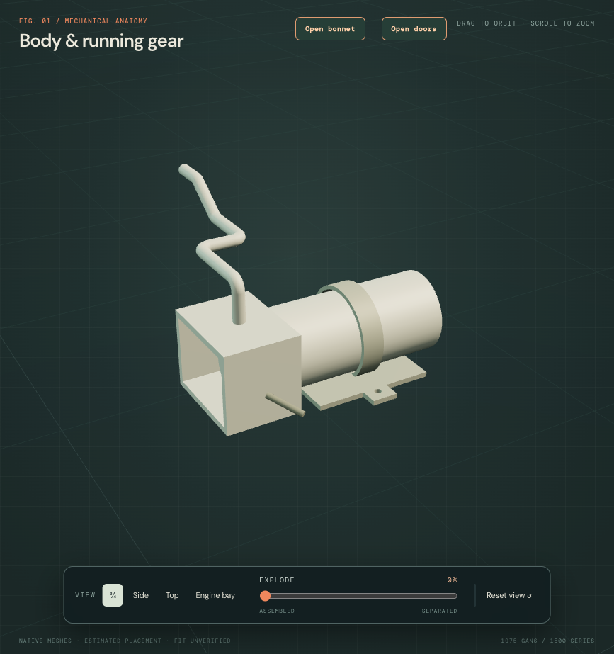
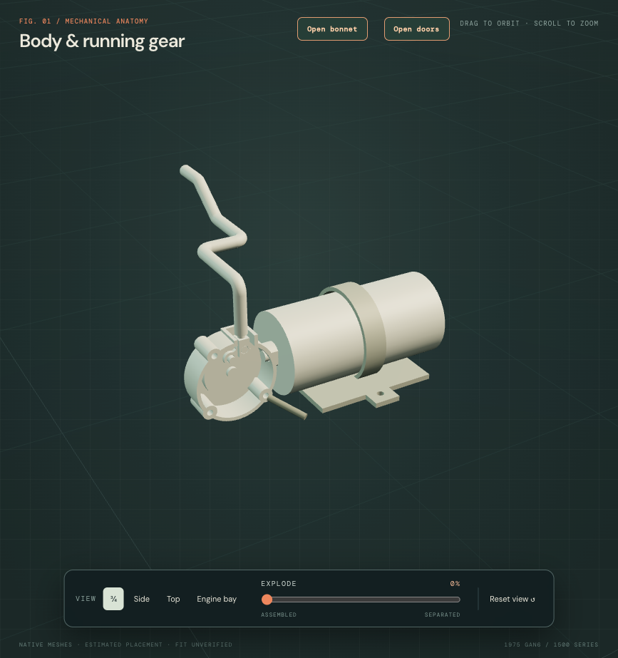
The chosen cover faces outboard on the X axis, perpendicular to the retained motor Z and initial casing Y directions. This clocking is a reconstruction hypothesis, not an observation of the installed unit. Main radius 34 mm, 23 mm case depth, approximately 3 mm walls, 2 mm cover, three fixing locations and every shaft/port/link section remain estimates. The motor can, mount, lead, downstream casing paths, wheelbox axes and parked arms/blades stay. The old disc-center Y/Z stations are retained; its spindle axis changes.
The smooth input stub ends before the wheel. No worm/gear teeth or engagement, complete bearing/retainer stack, park switch, electrical circuit or loaded rack motion is reconstructed. No 110-degree or other sweep variant is selected, and wheelbox tooth count and installed motor suffix remain unknown. Source contact or separation does not establish actual clearance. The cover’s inspection translation exposes its face; it is not a verified removal direction or service procedure.
This revision preserves the earlier scuttle and casing reconstruction. Older validation reports describe their respective stages; the current gearbox evidence and checks above define this change’s scope.