Cowl, guard and supports.
Expose the joints.
The observed formed upper cover now follows existing photo-surface tracks. A bounded reference placement moves the unchanged-sized radiator and cowl frame, now uses tapered body-side channel references with unregistered body joints and lowers the landing-panel tongue. Hidden cowl/guard joints, fitted dimensions and the complete coolant circuit remain unresolved.
Later front-drive revision: the main model now uses the photo-guided pitched fan and dished pulley. Its static fan/hose and fan/outlet intersections are zero; pump-housing and belt boundaries remain open. The before/after images and 2,783 mm³ retained-fan result below record the preceding cooling-cover revision, not the current fan pose.
Open the bay around the new hose.
The previous sloping apron, raised guard and long landing-panel tongue covered much of the photo-guided upper hose in assembled CAD. The visible upper cover is now reconstructed once, with a shallow transverse crown, forward return and folded right end. A separate upright frame and the retained catalog-sized radiator move to a bounded reference pose behind it.

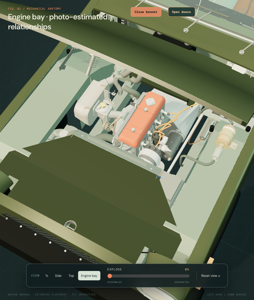
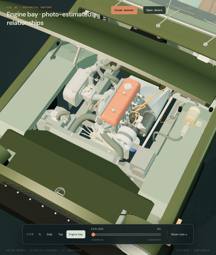
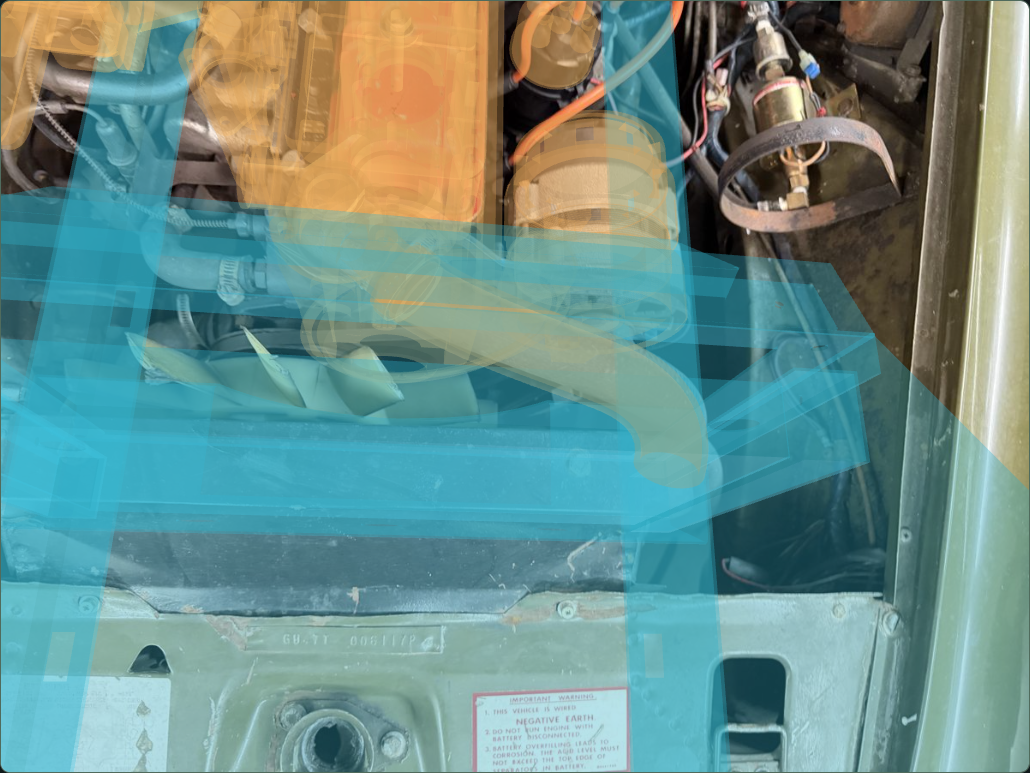
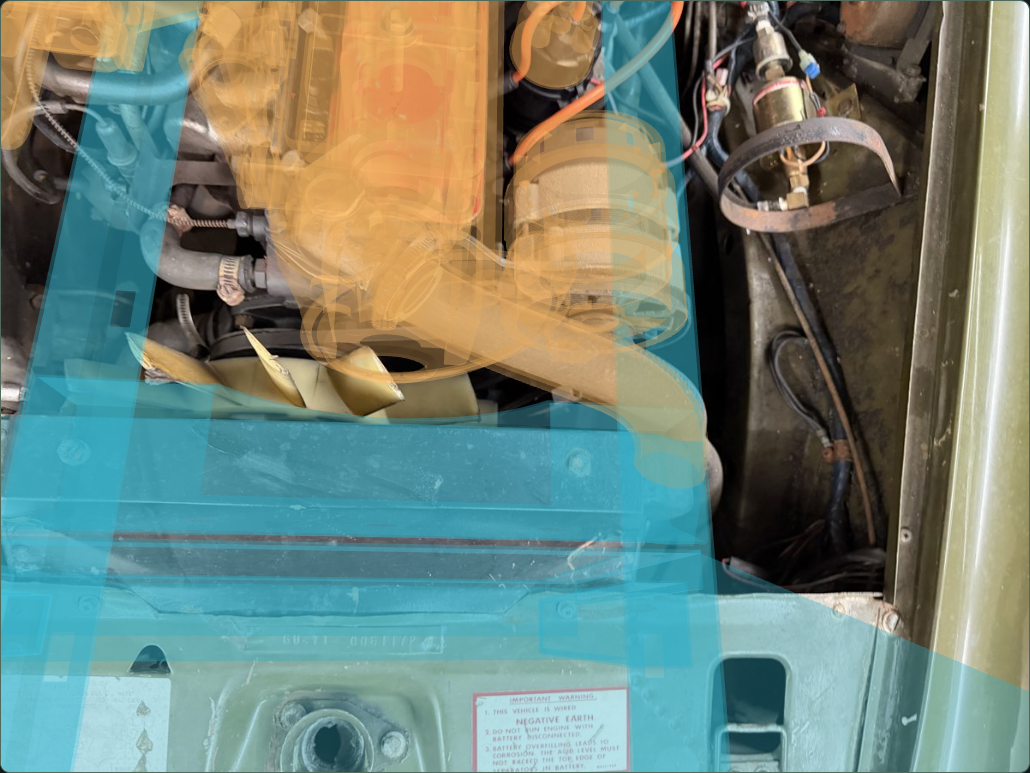
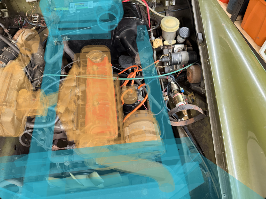
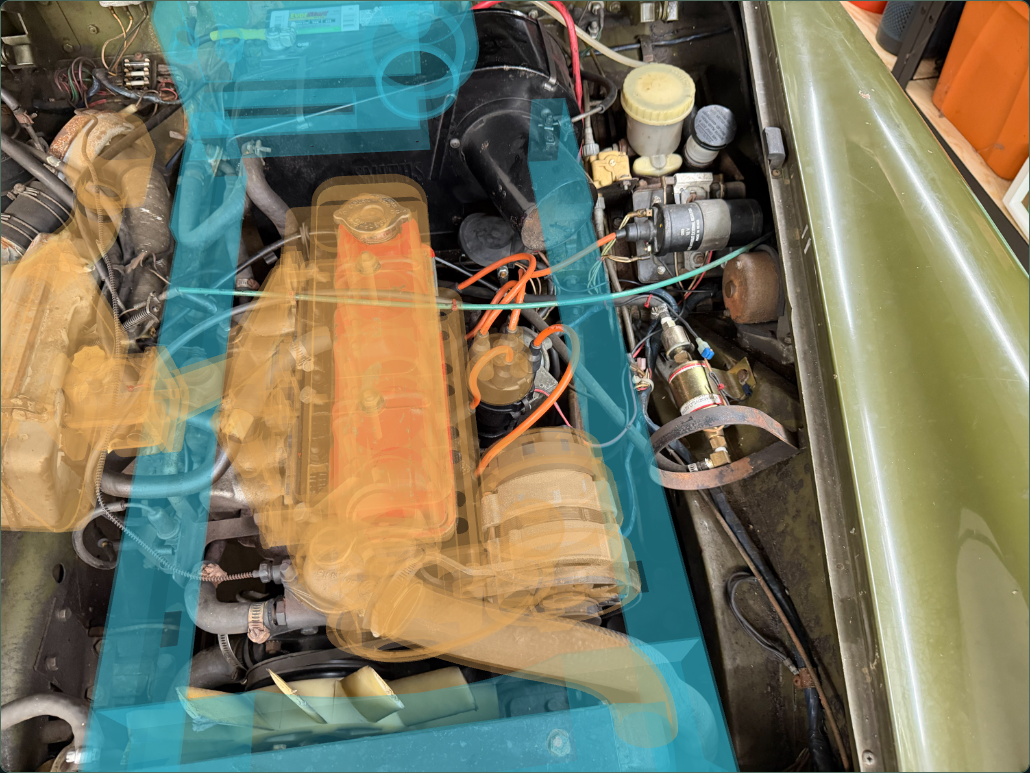
What guides the geometry
Reviewed main-roof tracks guide a shallow quadratic section across the cover and a longitudinal slope. Two manually interpreted head-face observations guide local cover-hole references. The left edge is cropped in the evidence: the retained 460 mm main-width comparison, unseen left extension, 35 mm right tab, 1.5 mm profile gauge and forward return are explicit construction choices, not fitted measurements.
The factory p86 and p88 distinguish cowl CHA281 from guard CHA420. This does not identify the photographed cover or reveal the hidden interface between those roles. The current exterior supplies the observed cover once; the former stacked apron/raised-guard silhouette is withdrawn. The original factory-architecture comparison export remains available below.
The radiator and upright frame share a rounded −60 / −100 / +100 mm construction translation in the conditional engine frame. This is guided by the cover/right-end envelope and retained size comparisons; it is not a triangulated hidden-radiator survey. The 422 × 258 × 40 mm catalog core stays unchanged. The photo-placement stage retained original body-foot envelopes and reconnected upper channels. Those feet and bridges are now superseded by the formed-bracket revision below. The shortened landing tongue now meets the declared cowl front/top reference while the nose, latch and access openings stay. All 31 other front-body/lamp meshes are byte-held.
A “top hose” can return to a low tank neck
Both factory drawings depict the long GRH525 hose returning down to a low tank neck. The old high-port interpretation was unsupported. The new radiator comparison closes that old opening and places the same neck/bead dimensions at an estimated local Y = −90 mm. This supplies the factory connection role; it does not establish this car’s radiator identity, actual port height or an early/late USA/Canada branch. The separate p87 / TSB75-A-6 branch remains unselected.
The revised upper hose no longer intersects the retained-size radiator core in the new reference pose; the earlier source overlap was about 20,612 mm³. A smaller source intersection of about 268 mm³ remains between the visible hose and the new cover. The retained static fan reference also intersects the photo-guided hose by about 2,783 mm³. Its old drive pose is not reconciled with the newer bay geometry. No fan, hose or cover relief is cut to erase these results. These are reconstruction results, not actual-car contact or working-clearance findings.
The photographed hose run stops before the hidden return. Its end and the low-neck mouth differ by about 263 mm in these model coordinates; the old lower-hose route and relocated neck differ by about 154 mm. Those are reference-station discrepancies, not measured gaps or hose-cutting lengths. Existing expansion plumbing also remains independently placed. No unobserved bend or support is added to claim circuit closure.
Workshop use: keep the cover, frame, relocated radiator, upper hose, alternator and landing structure visible when assessing obstacles. Local open holes and native geometry checks do not prove mounting strength, loaded hose shape, fan sweep, tool access, complete release order or a verified replacement/removal path. Separation remains illustrative.
Earlier attachment construction
The following records the original cowl/apron/guard and fixing comparison. Its former poses, stacked upper surfaces and long landing tongue are superseded by the current reconstruction above; factory role/count evidence and the unselected hardware comparisons remain.
Evidence behind the roles
Factory PDF p. 86 and p. 88 distinguish CHA281 cowl, CHA420 guard, four radiator screws/spring washers, two upper cowl screws and four side fixing screws/washers. They establish architecture and counts rather than fitted hole coordinates.
IMG_6853 and IMG_6854 show the broad black apron, upper strip/bolt context and adjacent fan/hoses. The supplier CHA420 photograph supports a separate raised sheet profile with two end holes. This is a candidate role comparison, not identification of the fitted strip. Supplier fixing listings give the nominal 5/16 × 1/2, 1/4 × 3/4 and No.10 × 1/2 screw comparisons used here. No new direct owner dimensions are applied.
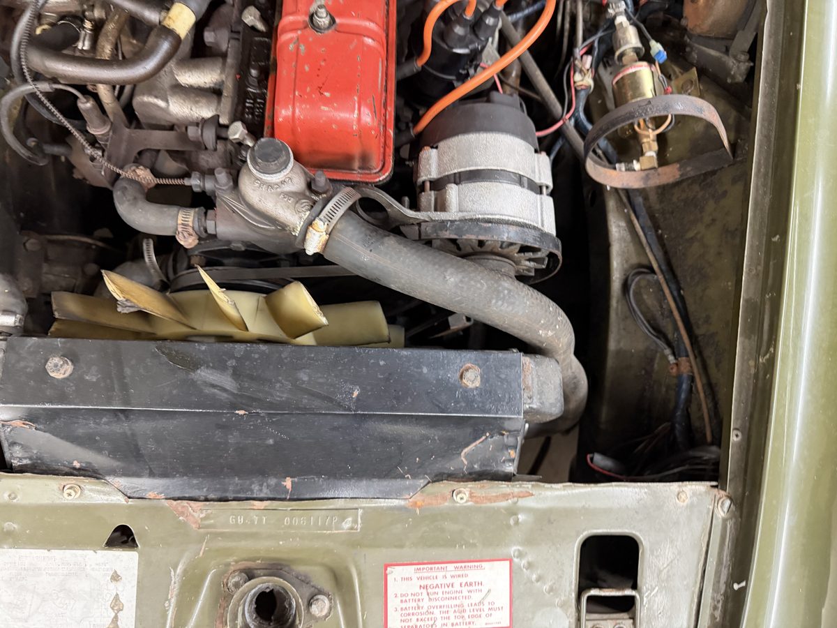
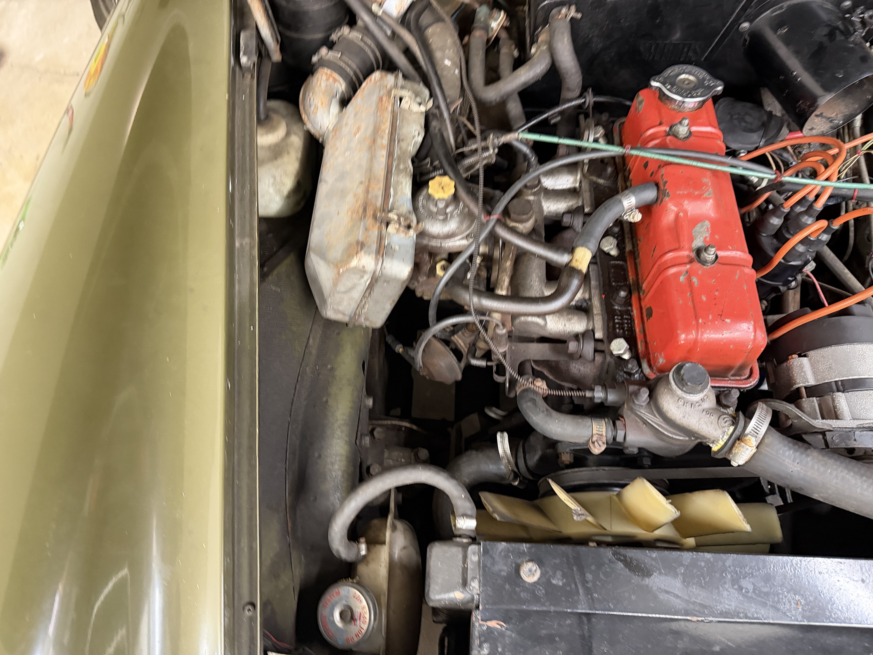
What changed in the model
| Relationship | Reference construction and limits |
|---|---|
| Cowl / radiator lugs | The existing cowl outside profile and source station remain. Four old hole cues are filled. Their X positions are retained, with rows moved from −68.56/128.56 to −108/164 mm: shifts of −39.44/+35.44 mm. This construction move prevents new lugs crossing source main/small hose ports; it is not a measured fixing map. New 4.25 mm-radius bores align with separate L-shaped lug and nominal 5/16 screw envelopes. The radiator pressure shell/export remains unchanged. |
| Cowl / body supports | Side bores align with folded support channels and four nominal 1/4 screw envelopes. The old body-foot centers are now superseded history; the formed channels retain the shared estimated cowl axes. Actual sections, base attachment, captive counterpart, joint spacing and support load remain unknown. |
| Guard / upper cowl | A raised channel/strip with two end holes sits on a plane parallel to the old apron. Two nominal No.10 screw roles share the new axes. Shape, thickness, holes, seating and the assignment of those factory upper screw roles remain comparisons. |
| Upper body attachment | The front landing-panel reconstruction now includes an estimated rear tongue toward the cowl front/top edge. That construction hypothesis does not identify a fitted joint or connect these upper fixing axes. The two new upper screw roles pass through guard/cowl only and do not establish a complete cowl-to-body support path. |
The radiator lug shapes represent possible integral/soldered attachment roles. Body-support base ownership and weld/fixing are unverified. Smooth screw, head and washer envelopes do not establish threads, locking, engagement, loaded seating or torque.
Keep the source conflicts visible
| Sampled source pair | Intersection |
|---|---|
| cowl retained profile with joint bores fan static | 101.553 mm³ |
| cowl retained profile with joint bores radiator upper open neck and bead comparison | 421.623 mm³ |
| cowl retained profile with joint bores radiator upper full hose route comparison | 1025.99 mm³ |
| cowl retained profile with joint bores radiator lower open neck and bead comparison | 402.124 mm³ |
| cowl retained profile with joint bores radiator lower full hose route comparison | 964.845 mm³ |
| cowl retained profile with joint bores expansion radiator small open neck comparison | 274.889 mm³ |
| cowl retained profile with joint bores expansion visible radiator hose hollow route comparison | 758.406 mm³ |
| cowl retained profile with joint bores expansion two smooth hose clip envelopes | 158.902 mm³ |
| cowl retained profile with joint bores expansion two unassigned mount fixing envelopes | 15.5885 mm³ |
| right body support comparison expansion two unassigned mount fixing envelopes | 23.2016 mm³ |
The cowl retains fan and main/small hose contacts. One body support also contacts an unassigned expansion-tank fixing envelope. These are reconstruction discrepancies, not measured interference or damage on the car. The old cowl is not cut around hoses or moved to erase them. Static fan contact does not validate full rotation, engine movement or operating clearance.
Workshop use
Inspect and isolate cowl, guard, lugs, body supports and fixing roles separately. Source axes and open bores support studying attachment relationships; display offsets are illustrative. The unresolved upper fixing counterparts, estimated panel joint and source fan/hose contacts prevent a claim of an installed mounting fit or tested withdrawal path. Drain/disconnection/support order, loaded structure, tool access and a verified replacement procedure remain unestablished.
Native exports
Eight source meshes contain fifty-six valid STEP solids. Construction checks gauge shared cowl/radiator, cowl/body and guard bores. Browser checks verify metric placement, selecting/isolation, open axes and screw occupancy, declared inspection movement, preserved source contacts, study/download links and mobile layout. They do not validate installed fit.
Folded radiator body brackets
The active cooling model already used connected supports in its conditional photo frame. Their cubic feet and diagonal bridges lacked a recovered body attachment map. Those assumptions are now withdrawn, and each support is a single tapered channel with two rounded returns. The web center, vertical span and two cowl-hole axes per side stay. Six other cooling groups, the upper cover, radiator placement and neighboring body sources are unchanged.
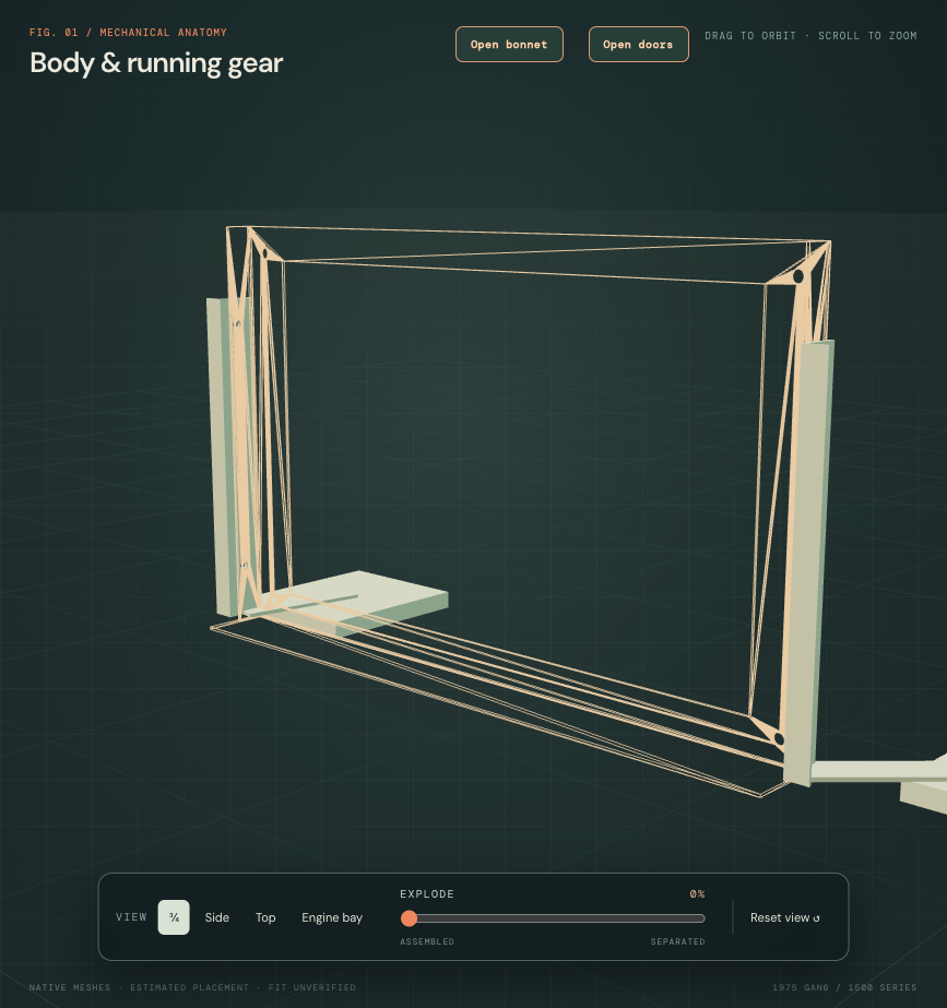
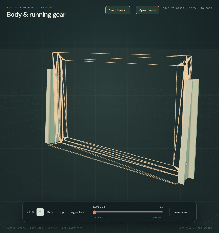
Inspect the left channel ↗ · Inspect the right channel ↗
Factory body plate, p234, identifies handed AHA5624/AHA5626 brackets, separately from the cowl and its screws on cooling pp86/88. British Motor Heritage’s own catalog confirms those radiator-bracket roles. Kilmartin’s own AHS049 photograph shows the tapered folded pair. These sources support architecture, not this car’s fitted dimensions or weld map.
The former foot centers are retained only as superseded history. No new body receiver, attachment hole, long bridge or weld has been invented. The selected 3mm projected section, 3mm inner radius, return width, taper and mirrored form are estimates. They are not a manufacturing pattern, verified handed pressing or structural/load approval.
Owner IMG_6853/6854 supply installed cooling surroundings, but do not survey the hidden bracket/body attachment. Cowl-hole bores remain open construction interfaces; their source spacing and hardware do not prove fitted seating or access. The right bracket overlaps the retained front spring-pocket source by460.21mm³, compared with267.23mm³ before. No neighboring body source was moved or cut. This is a reconstruction discrepancy, not measured interference in the car. The removed feet formerly overlapped both rail references; withdrawing them does not establish a body joint or prove fitted clearance. No new applicable radiator removal procedure or extraction path was verified; inspection separation remains illustrative.