Tank to radiator.
One visible relationship.
IMG_6849 and IMG_6854 show the pale seamed tank, fitted cap and an arched hose to a small radiator connection. The whole-car model now separates a hollow tank, cap underside envelope, open radiator neck, hollow hose, clips and mounting-ear/fixing comparisons.
Use the evidence already supplied
IMG_6849 ↗
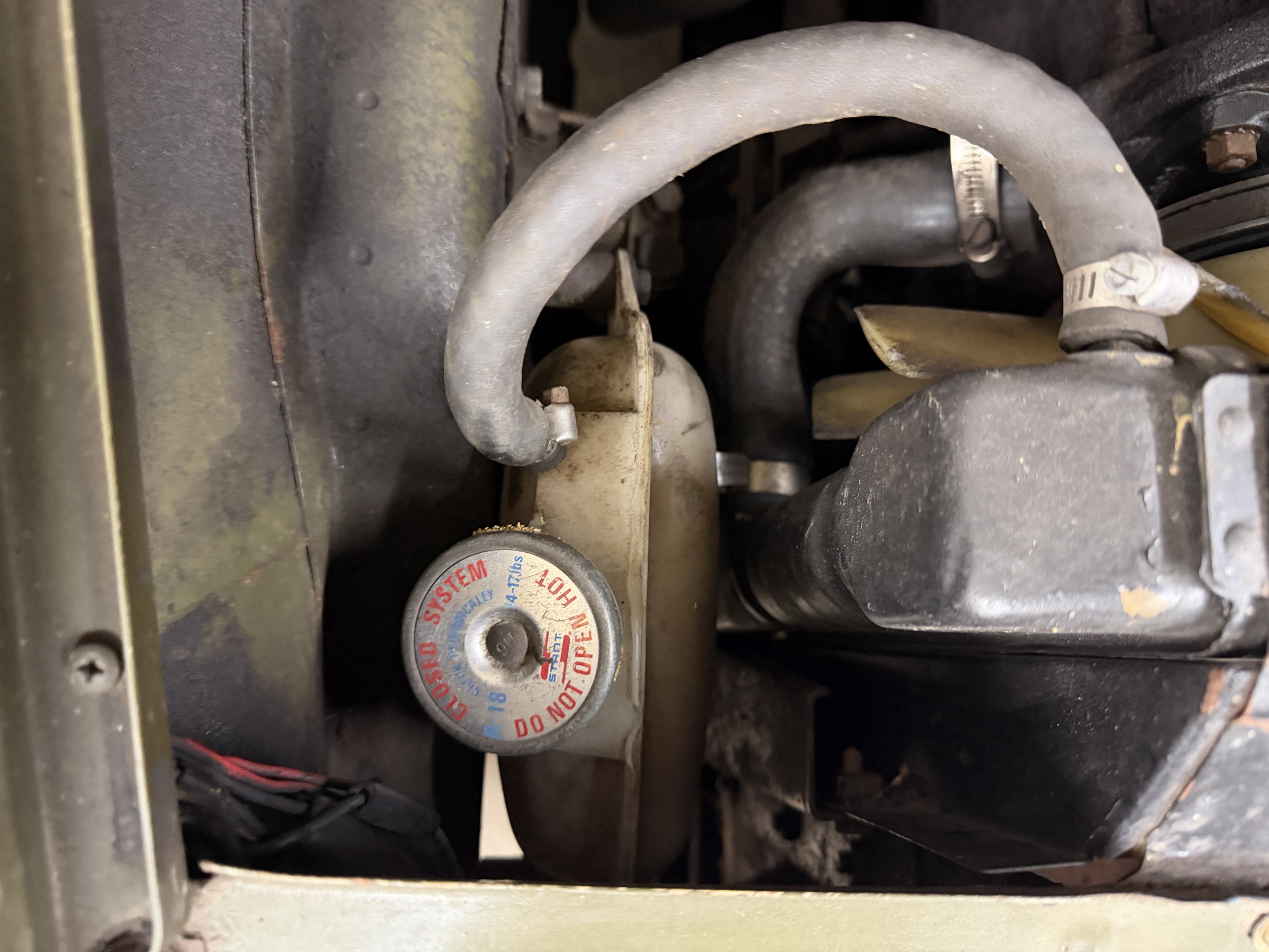
The close view shows the tank seam, cap and visible hose with clips at tank/radiator. The cap’s printed 14–17 lbs does not establish its underside seal type or compatibility.
IMG_6854 ↗
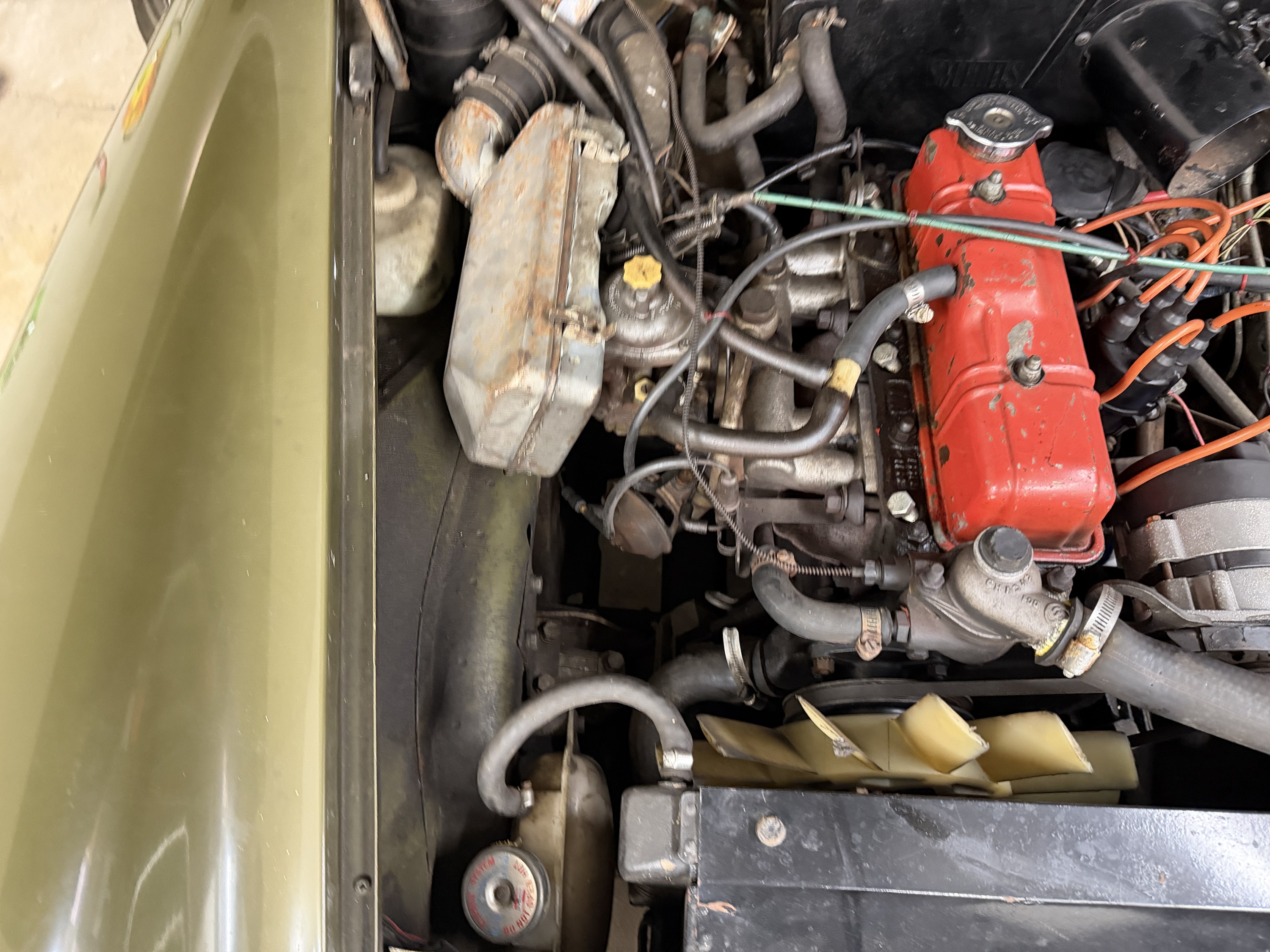
The broader view locates the tank and hose alongside the cowl, fan, main cooling hoses and intake. It is context rather than a calibrated three-dimensional survey.
Keep the factory branches distinct
Factory PDF p. 86 illustrates the standard radiator-to-expansion-tank hose and two-ear tank mounting roles, listing ARA326, GRC110, two fixing bolts and GRH1002M hose at 11 inches (279 mm). The visible relationship is compatible with this architecture, but does not establish those fitted identities. The factory hose length is a catalog specification, not a cutting length derived from this model.
P. 87 TSB75-A-6 instead lists URP1148/URP1145, paired brackets, thermostat-housing branches and a separate spill tank for the specified early USA/Canada range. P. 88 distinguishes later GAN6-166304-on arrangements. No spill tank or extra thermostat connection is invented to turn the observed assembly into either catalog configuration. The existing cooling-history study retains the cap and bulletin identification limits.
Geometry and provenance
| Interface | Construction and uncertainty |
|---|---|
| Tank shell | The prior 94 × 145 × 66 mm outside loft, seam and engine-relative station remain photo-layout estimates. A smaller inner loft opens the shell; its varying thickness is not a measured or constant wall section. Filler and hose neck bores are estimates. |
| Cap | Prior visible crown/lip bounds remain. An open skirt exposes an underside envelope, with no modeled locking lugs, seal lands, spring, pressure valve or rated sealing behavior. |
| Radiator connection | The small rear-facing neck and 10 mm-radius tank aperture are new estimated stations and sections. Only the corresponding radiator tank mesh changes; the retained core, main hoses and other source meshes remain unchanged. The open neck has a 7.5 mm bore radius. |
| Hose and clips | A hollow arch connects the source necks through estimated straight engagements and Bezier control points. The 13.5/10.5 mm outside/inside radii, route, band envelopes, stretch, sealing and cutting length are unverified. |
| Mounting | Two integral/molded-role ear comparisons and unassigned bolt/washer envelopes expose factory mounting roles. Their axes and dimensions are estimates. No hidden body bracket, fitted support, thread, torque or complete load path is established. Displaying ears separately does not imply detachable ears. |
No direct owner dimensions are newly applied. The hose and small neck intersect the independent cowl reference in the source pose. No cowl cut, tank relocation or hose rescaling is used to conceal the conflict.
Retained cowl contacts
| Source part / cowl | Intersection volume |
|---|---|
| radiator small open neck comparison | 274.889 mm³ |
| visible radiator hose hollow route comparison | 758.407 mm³ |
| two smooth hose clip envelopes | 158.902 mm³ |
| two unassigned mount fixing envelopes | 7.7942 mm³ |
These are reconstruction discrepancies, not findings of physical interference on the car. Sampled static fan contact is absent for these new source solids, but no full fan rotation, operating clearance, engine movement or unmodeled body obstacle is verified.
Workshop boundary
Selection and isolation distinguish the tank, cap, hose, clips, small radiator neck and mounting roles. Separation offsets illustrate inspection only. Actual cap compatibility, loaded seal, hose release and drain/fill order, support, tool access and verified tank/hose withdrawal paths are unresolved. The model does not certify pressure containment or a replacement procedure.
The unregistered heater-return comparison remains independent. This visible tank-to-radiator relationship does not resolve its pump/manifold ports or either untraced heater hose boundary.
Cooling attachments
Separate cowl, guard, radiator lugs and body-support joints now expose shared estimated fixing axes. The unresolved front landing-panel attachment and source fan/hose contacts remain explicit; these are not fitted mounting or clearance results.
Native exports
Seven source meshes contain fourteen valid STEP solids. Construction checks verify open tank/radiator necks and local hose/neck nonintersection. Browser checks cover metric scale, picking, open boundaries, source counts, inspection ownership, links and responsive layout. These do not verify fitted dimensions or readiness.