Current revision: retained lower bend and estimated radiator return ↓
Upper cooling.
Reconstruct the visible run.
The upper outlet, plug, engine-side clamp and visible radiator-hose run now follow the existing owner photographs in the conditional engine frame. The old pump seat and radiator port remain unregistered. The original complete upper-hose route is retained as a separately selectable comparison.
Follow the photographed outlet and hose.
The former outlet pointed straight sideways, and its complete hose reference passed through the revised alternator casing. Reviewed plug-face observations, casing/bolt features and hose-surface tracks now guide an asymmetric casting, diagonal neck and curved visible run. The final open hose end stops before the unverified radiator joint.

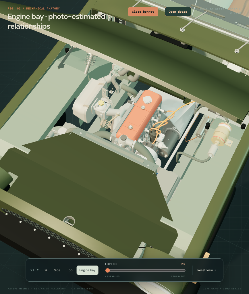
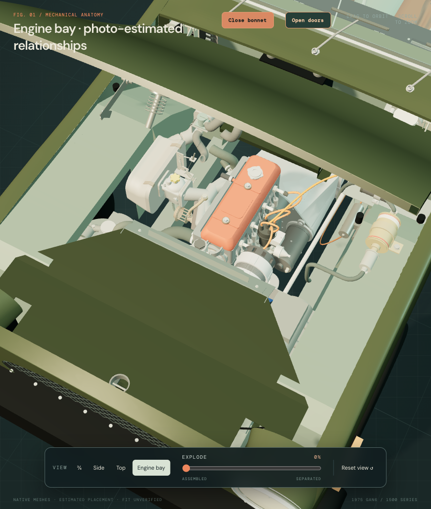
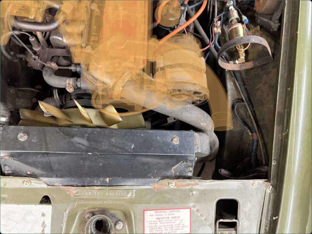
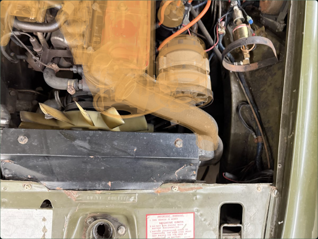
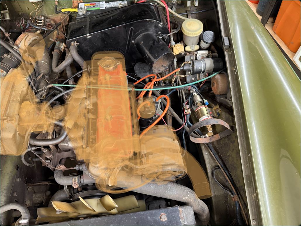
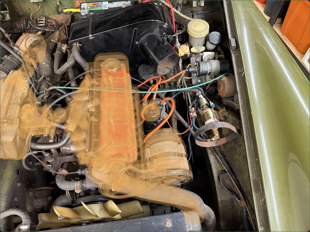
Geometry and evidence remain separate
Nine native groups contain one connected rebuilt outlet, one connected hollow hose and seven preserved comparison shapes. The rounded plug station is −30 / 139 / 230 mm in the provisional engine frame. The 36 / 40 mm neck/bead and 44 / 36.6 mm hose outside/inside diameters retain their earlier comparison bases. These are not new owner measurements.
Visible bolt features guide a 56 mm construction span on the rebuilt casting. The independent ruler-photo gasket retains its 70.5 mm pitch; the source gasket and thermostat element are hidden in the assembled view and appear when selected. Neither is identified as a fitted compatible part. Bolt lengths and cap/seal/clamp shapes remain source comparisons; their placement, handed assignment, neck angle, 40 mm base opening, internal passages and unloaded fit are estimates.
The hose no longer intersects the sampled alternator case, compared with about 13,418 mm³ in the previous source layout. At this stage it intersected the old radiator-core reference by about 20,612 mm³; the rebuilt outlet also overlaps the old pump-housing reference by about 292 mm³. Those are reconstruction discrepancies, not actual-car interference or clearance findings. The old pump-seat/gasket centers differ by about 57 mm, and the open hose end is about 79 mm from the old radiator-mouth reference. These are model-coordinate discrepancies, not measured gaps.
The radiator, pump and cowl are not moved or trimmed to erase those results. The subsequent cover/radiator/frame reference revision removes that core/hose source overlap and exposes the hose in assembled CAD. A smaller cover/hose contact and the unobserved pump/return/circuit interfaces remain unresolved.
Workshop use: inspect the separate outlet, plug/seal, engine clamp and visible hose beside the alternator. No loaded support, seal compression, pressure/flow behavior, fitted circuit closure, safe release order, applicable verified replacement procedure or removal path is established. Display separation is illustrative.
Earlier complete-hose construction
The following describes the retained nine-group radiator/tank/hose source. Its old upper route is now an unfitted comparison, superseded in the assembled view by the photo-guided visible run above. The lower route and radiator/tank references stay.
What the sources establish
Factory 1500 cooling plate, PDF p. 88, separates radiator, GRH525 top hose, CHA603 lower hose, clips, cowl and tank plumbing. It establishes architecture, not these fitted profiles, neck positions or hose cutting lengths. The maintained 422 × 258 × 40 mm core is an aftermarket core-size comparison, not an owner radiator measurement.
Owner IMG_6853 shows the upper hose, its engine clamp, cowl and visible bend toward the radiator. IMG_6896 supports local lower-hose recognition. The hidden radiator joints are not measured in those views. New radiator necks and final hose approaches are explicitly estimated; image perspective is not treated as a calibrated clearance measurement.
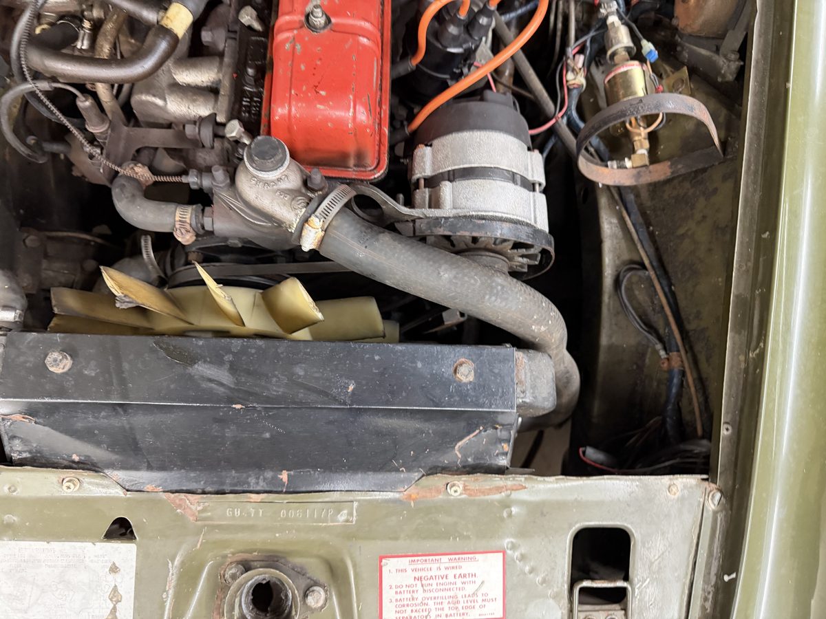
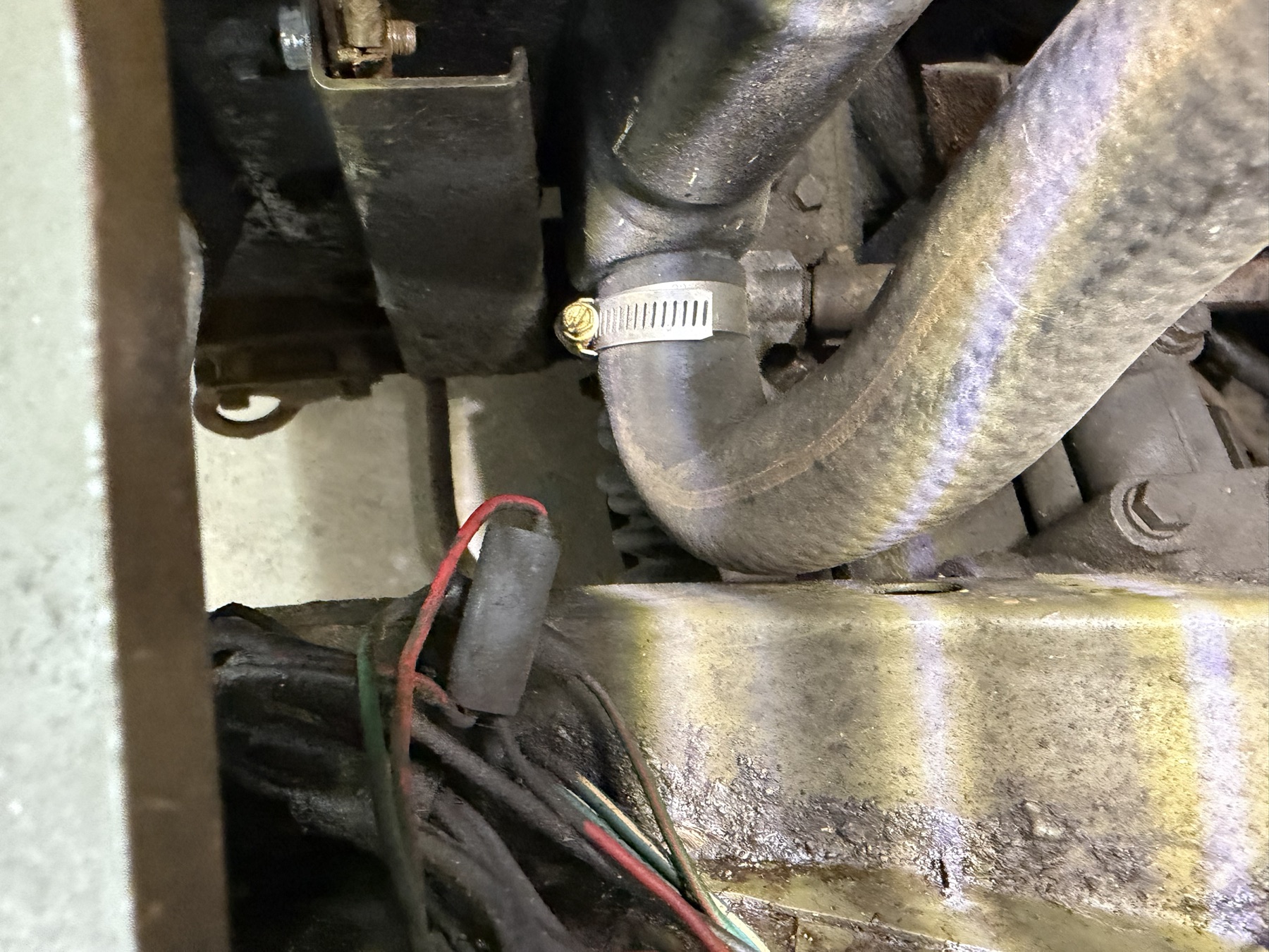
Keep early North American plumbing separate
Factory p. 87 assigns early USA/Canada cooling modifications through GAN6-166303 to TSB 75-A-6. The next plate has a separate GAN6-166304-on USA/Canada branch. The fitted expansion tank, small-hose routes and thermostat variant are not selected from a generic “1500” listing. Existing tank/cap and small-hose boundaries remain unchanged.
Which geometry is retained, inherited or estimated?
| Relationship | Basis and limit |
|---|---|
| Core and tank outer envelopes | Same maintained core dimensions, side-tank outer bounds, source frame and Z station. The core remains opaque, without coolant tubes or thermal/fluid simulation. |
| Engine hose ends | Diameter bases come from the maintained native export’s checks. Its public comparisons remain comparisons; no new direct reading is claimed. The lower-end source stays. The newer upper outlet/clamp revision is documented above. |
| Tank interiors / radiator necks | Estimated 1.2 mm tank walls and core-facing windows. Port stations, hollow necks, beads, sections and engagement are construction choices, without fitted identification. |
| Hose approaches | Smooth Bezier reference bends join the retained engine socket axes/stations to estimated radiator approaches. The former partial, unmeasured curve surfaces are replaced in this display. A valid hollow shell or coincident socket does not establish rubber stretch, seal compression, loaded hose shape or manufacturing bend radius. |
| Clamps / separation | Recognition envelopes with unmeasured size, clocking and release axes. Parts separate for inspection, breaking their connections illustratively. |
The prior fan/cowl reconstruction overlap is retained. Neither radiator nor fan is moved to make this study pass. The new necks intersect the current cowl source solids: approximately 421.6 mm³ at the upper and 402.1 mm³ at the lower neck. The two historical hose shells have zero source-solid overlap with that cowl in their original static pose. This is not a current whole-bay clearance assessment. These results concern the reconstruction only; they do not establish fitted or operating clearance. Neck clocking/position and cowl construction still need reconciliation.
Workshop use and remaining gaps
Inspect the core/tank boundary, open neck, hose socket and separate clamp before considering a hose or radiator replacement study. Keep the cowl, engine drive and body supports visible when assessing what evidence a removal rehearsal would need. The hidden radiator joint geometry, complete early coolant/expansion circuit, actual fixing map and fitted fan/hose/body clearances remain unresolved.
This display does not establish a drain/fill procedure, pressure test, clamp setting, safe release order or verified removal path. Source-solid and viewer checks concern construction consistency and inspection only. No supplied photo or measurement is requested again.
Visible expansion connection
Owner-photo tank-to-radiator connection now has separate hollow tank, neck, hose and mounting-role comparisons. Only the matching estimated small aperture changes the negative-X radiator side tank. Cowl contacts and fitted variant/registration uncertainty remain visible; the heater-return circuit remains open.
Cooling attachments
Separate cowl, guard, radiator lugs and body-support joints now expose shared estimated fixing axes. The unresolved front landing-panel attachment and source fan/hose contacts remain explicit; these are not fitted mounting or clearance results.
Native exports
The maintained full engine export remains unchanged. The whole-car viewer retains this radiator/lower-hose assembly. Its old upper route is separately selectable, and the newer upper-cooling photo assembly supplies the current visible run. Ignition and fuel references in the old bay group remain.
Upper hose, through to the low radiator neck
The upper-hose reference now includes a return to the retained low radiator neck. All original photo-guided hose material, the eight outlet/fastener/clamp groups and every surrounding source pose stay. The hidden return is a construction estimate between existing stations; it is not an identified fitted GRH525 hose.
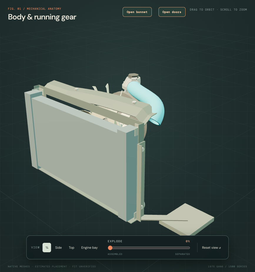
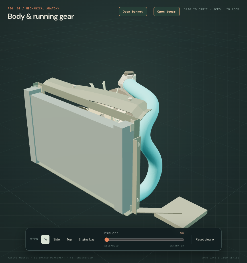
Factory 1500 cooling plate p86 and continuation p88 support the top-hose/low-neck connection architecture. They do not supply the fitted bend coordinates or select this car's radiator and expansion-system branch. The new return uses two smooth construction bends and a straight terminal. The retained 44/36.6 mm diameter comparison, unloaded bead relief and chosen 22 mm socket engagement are not a measured or compressed joint.
The hose is one valid native solid. Scoped checks retain all original material, keep eight other mesh groups identical, and find no source intersection with the radiator neck, tank, core or static fan. They do find about 37.4 mm³ with the retained clamp and 170.7 mm³ with the cowl frame. The earlier approximately 268.2 mm³ cover/hose contact stays. No clamp, frame, radiator or hose endpoint is moved to manufacture clearance. These source discrepancies remain visible for registration work; they are not findings about physical interference on the car.
Workshop relationship: the upper hose joins the thermostat outlet to the radiator; the clamp references belong at those separate joints. This assembly is useful for inspecting the connections and surrounding obstacles. It does not establish pressure behavior, actual clamp seating, safe release order or a verified hose withdrawal path. Pump/housing, lower hose, heater and expansion routes remain independently registered.
Manual access: the local AKM4071/B scan's title page includes AKM3267 and all markets, but these downloaded segments omit the US engine and cooling procedure pages. The UK cooling instructions are not substituted for the North American procedure. Read the actual access and reading status ↗.
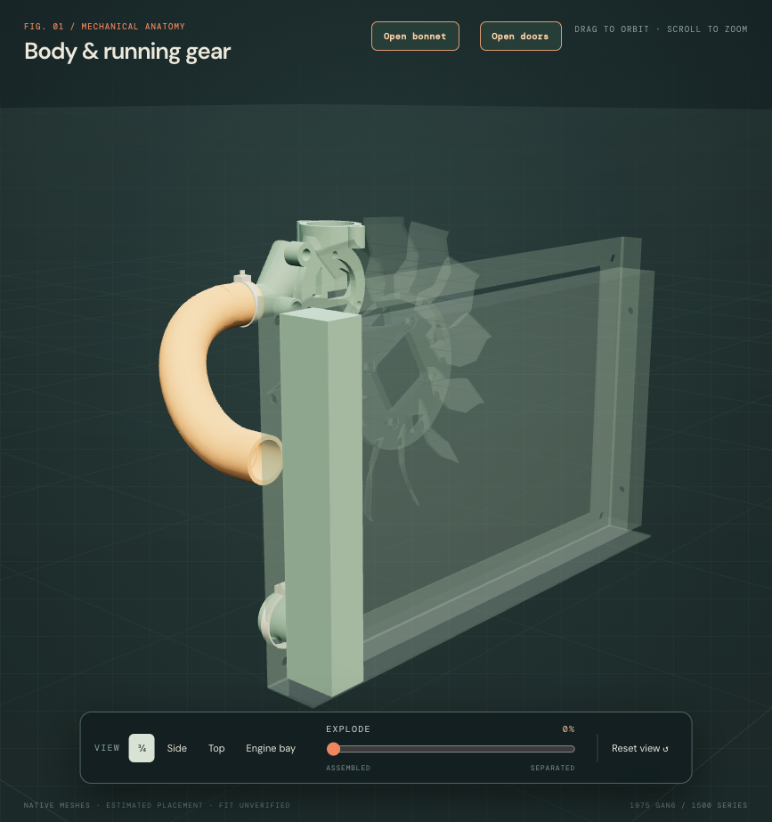
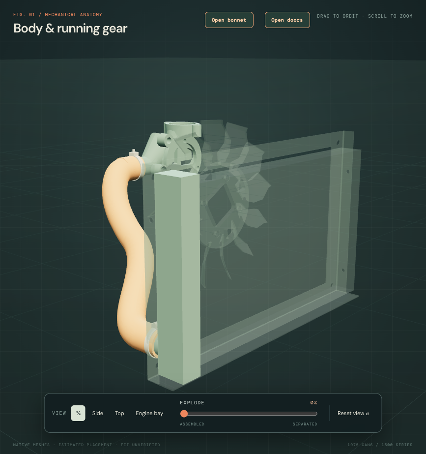
The lower hose now reaches the retained radiator
The earlier full lower-hose comparison still ended at the radiator’s former station after the radiator reference moved. The current assembly replaces that curve with the existing owner-photo-guided housing-end bend and socket, extended by an explicitly estimated hidden return to the unchanged lower radiator neck. The engine housing, radiator, fan, cowl and both clamp references stay in their preceding source poses. The eight other radiator-source meshes remain identical.
Owner photo, factory role and unselected variants
Owner IMG_6896 supports the local housing-end bend, clamp and nearby obstacles; it does not reveal a calibrated complete radiator connection. The retained engine-source bend runs to drawing endpoint X−186/Y−74/Z258 mm. Its 43/35 mm outside/inside diameters retain their original derived-comparison status. No new owner measurements are applied.
Factory plate 86 lists GRH534 as a lower hose within that plate’s stated market/change-point scope. Plate 88 separately lists CHA603 in the later USA/Canada arrangement from GAN6-166304. Neither identifies the hose or radiator fitted to this1975 car. Earlier USA/Canada arrangements and the project’s TSB75-A-6 reference remain separate. The geometry therefore carries a lower-hose role without selecting a catalog branch or treating an aftermarket shape as fitted evidence.
What the connection establishes
The new return starts tangent to the retained local bend and reaches the radiator neck on its existing +Z axis, with an estimated22 mm unloaded engagement. All four Bezier control points, terminal straight and bead relief are declared construction choices. The approximately47.25 mm sampled minimum centerline radius checks geometric regularity; it is not a rubber bend rating, actual cutting length or proof of a molded hose shape.
Native validation finds one valid connected hose solid, with zero original bend material lost. Both socket wall/bore probes pass, and the mesh/native volume difference is approximately0.183%. The sampled housing, radiator neck/tank/core, static fan, cowl/cover and upper-hose source intersections are zero. The radiator-end clamp envelope overlaps the hose by approximately36.965 mm³. That is an unresolved source-model contact, not a finding about actual clamp compression or physical interference. No obstacle was adjusted to improve the contact results. These checks do not establish operating fan sweep, loaded clearances, pressure behavior or fitted accuracy.
Workshop boundary: this makes both ends and surrounding obstacles inspectable as one hose reference. The original partial bend and original complete route exports remain available as historical evidence. Source selection and separation are illustrative; no safe release order, tool access, drain/refill process or verified withdrawal path is encoded. The accessible manual segments omit the North American cooling procedure pages, so UK instructions are not substituted. Pump-to-housing, heater and expansion connections still require their own registration and branch evidence.
An open tube-and-fin core
The former radiator core was an opaque solid block. It now has flattened crossflow tubes, open header passages and a separate thin fin field. The supplier's own NRP1028 photograph supports the broad tube-and-fin architecture between side tanks. It does not identify this car's fitted radiator, its material, internal pass arrangement or dimensions. Existing owner IMG_6854/6896 shows installed cooling-stack context rather than a countable core field.
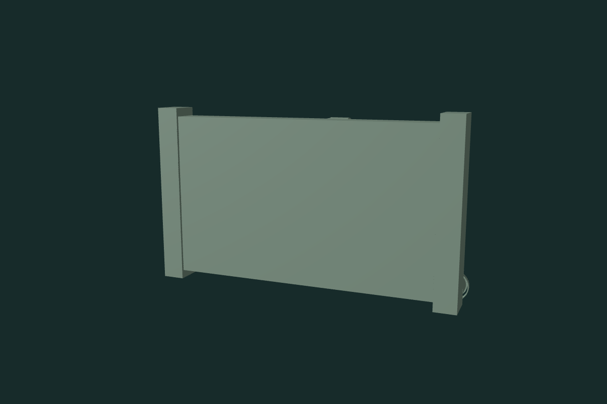
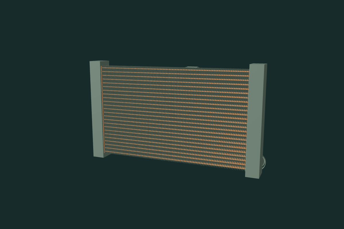
Retained references: the 422×258×40 mm envelope and its installed station stay. These are earlier reference dimensions, not new owner measurements. The eight tank, neck, hose and clamp mesh records and native group volumes stay. Cowl, guard, fan, radiator brackets, expansion tank and engine/body frames are unchanged.
Estimated internal architecture: 24 tube levels in two depth rows, selected 3×14 mm outer sections with 0.35 mm walls, 1.2 mm header plates, and 96 sparse flat sheet-fin comparisons with 0.15 mm gauge. Counts, sections, radii and pitch are selected construction values. The flat fins do not recover actual corrugation or louvres. Open passages and thin material do not validate sealing, brazing, baffles, coolant distribution, pressure integrity, heat rejection, airflow or fan performance.
Workshop connection: the core remains part of the radiator assembly beside the existing cowl/guard and hose connections. Isolation and separation expose the architecture; they do not establish radiator dismantling, fin repair, draining, release order, loaded clearance or a verified withdrawal path. The common fitted engine/body mounting frame remains unresolved.
Formed side-tank faces
Both rectangular tank fronts now have a broad crowned face and rolled end-transition comparison. The supplier's own radiator photograph supports formed tank morphology, without identifying the fitted radiator or supplying measured sections. Existing owner IMG_6854/6896 mainly supplies cowl, fan and hose context; the hidden tank section and joints remain unknown.
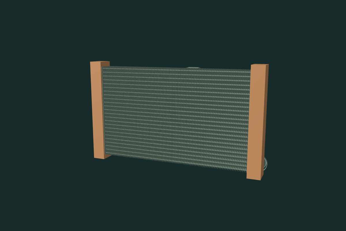
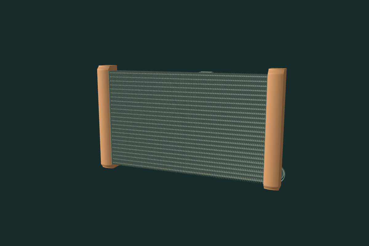
Selected estimates: 4 mm transverse crown and 8 mm end recession over 12 mm. The front wall uses a 1.2 mm projected-Z section; side/end coordinate insets use the same selected value. These are construction choices, not normal material gauge, measured end radii, a traced pressing, forming or brazing specifications. Both tanks repeat an assumed morphology.
The outer bounds, complete flat rear receiver sheets and their existing openings are retained. The core-facing windows stay open. Eight other native groups/mesh records, including the instanced fin pack, necks, hoses and clamps, stay. All source transforms and inspection offsets stay. Native checks distinguish material/profile changes from the unchanged receiver faces and report scoped source contacts. The cowl, guard and body brackets retain their earlier owner-photo reconstruction; no supported hidden joint or receiver map was recovered.
Workshop connection: the separate tank and core display explains their relationship; it does not make the tank a verified removable part of this radiator. Joint ownership, seals, brazing, pressure integrity, baffles, flow, thermal behavior, support, loaded clearance and replacement/removal remain unverified. No new seams, holes, drains or fixings are inferred.